Going off at a tangent

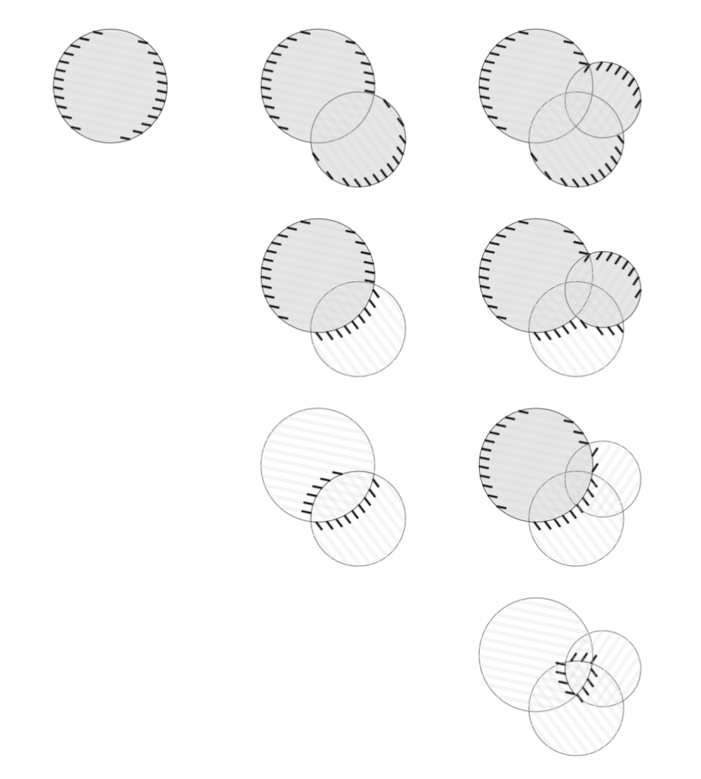
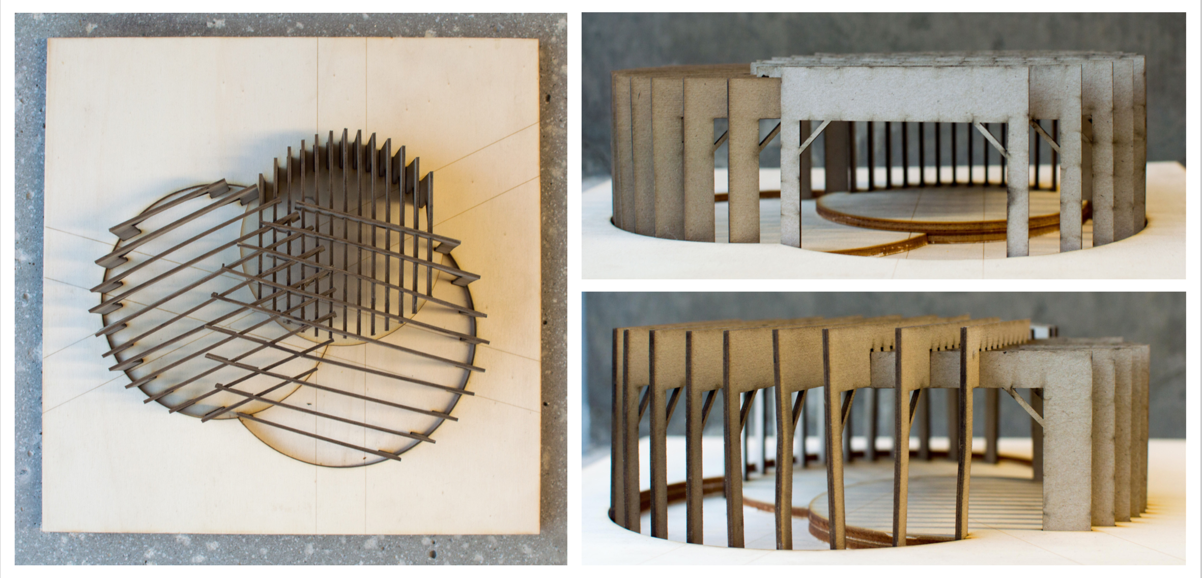
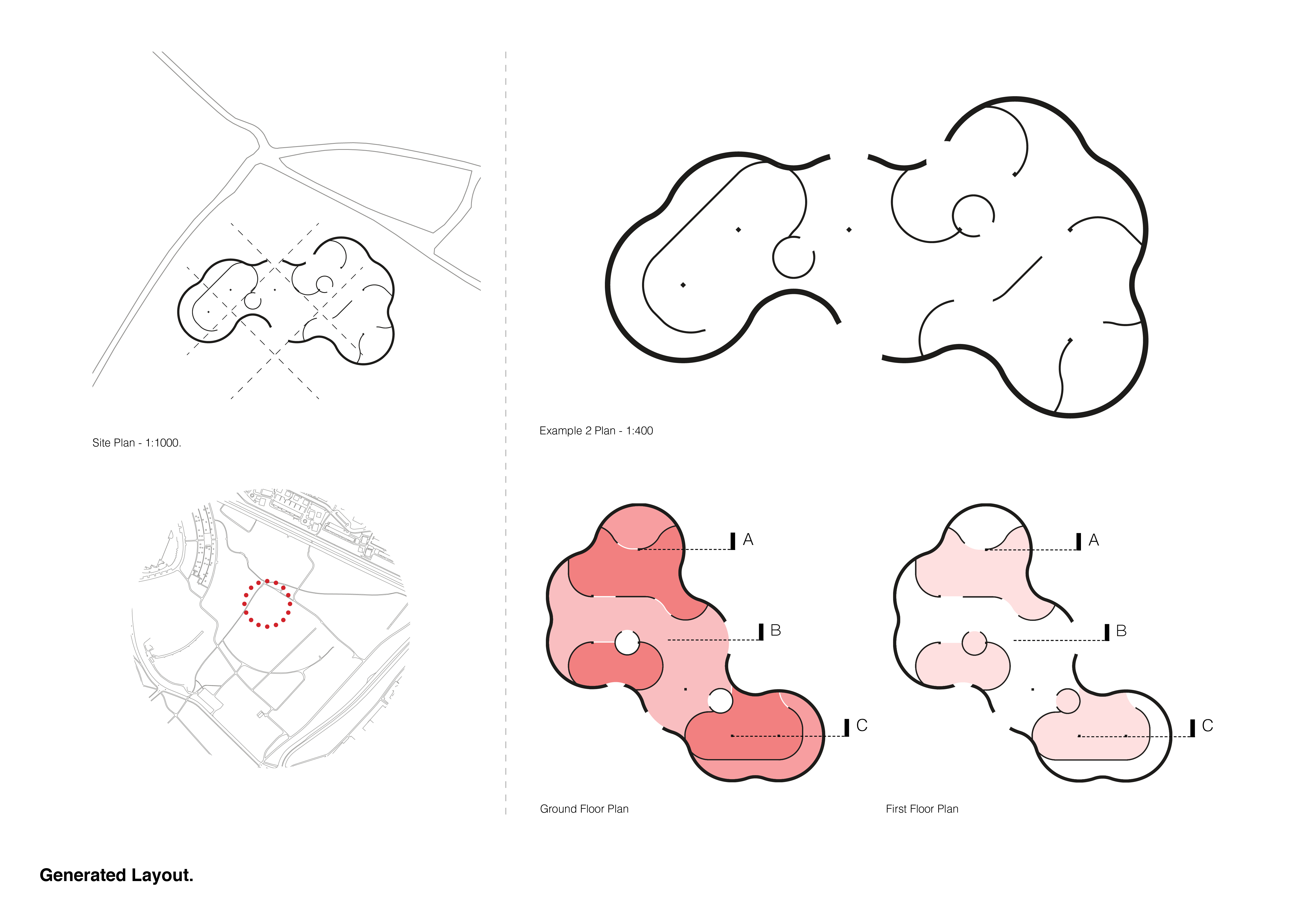
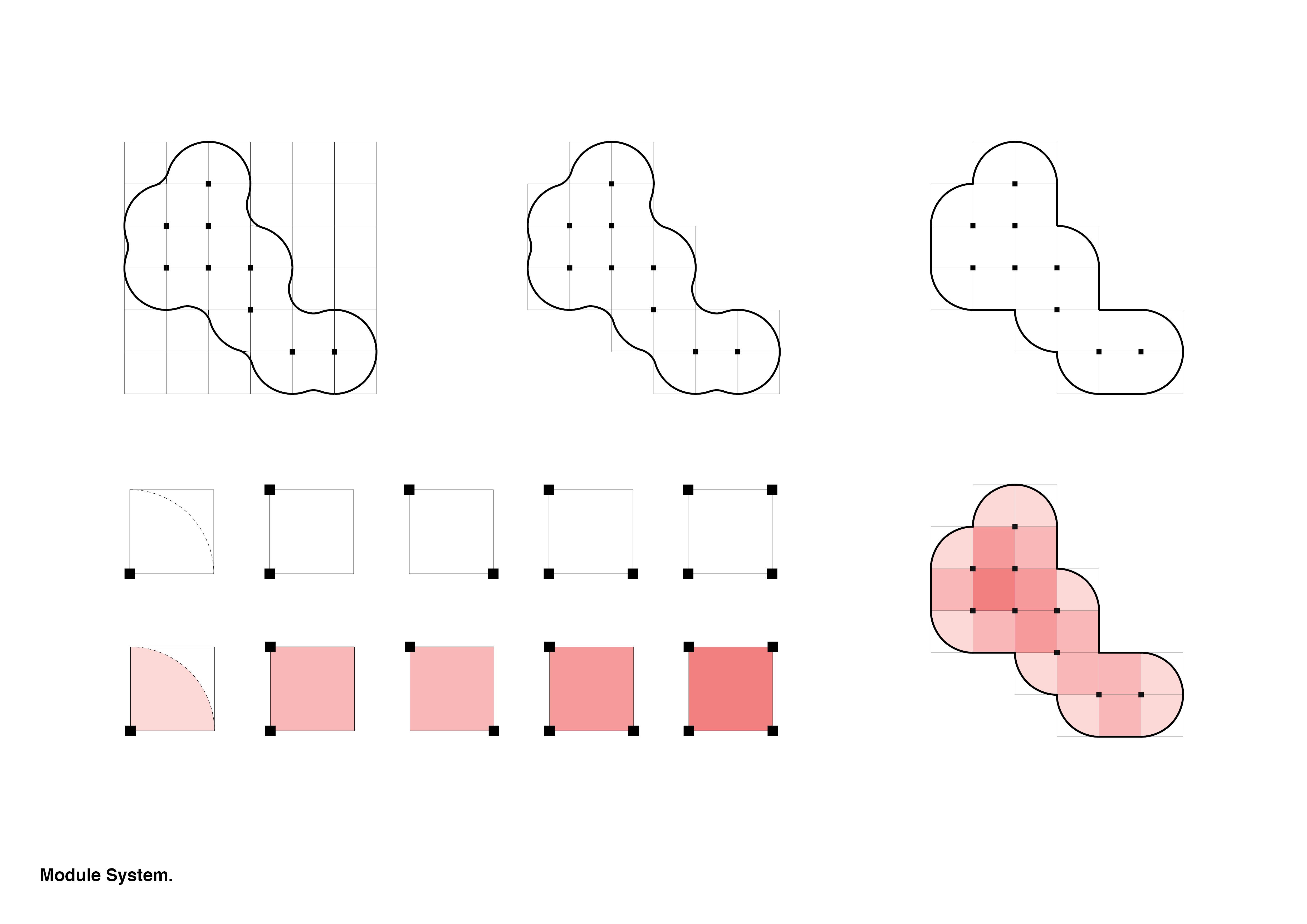
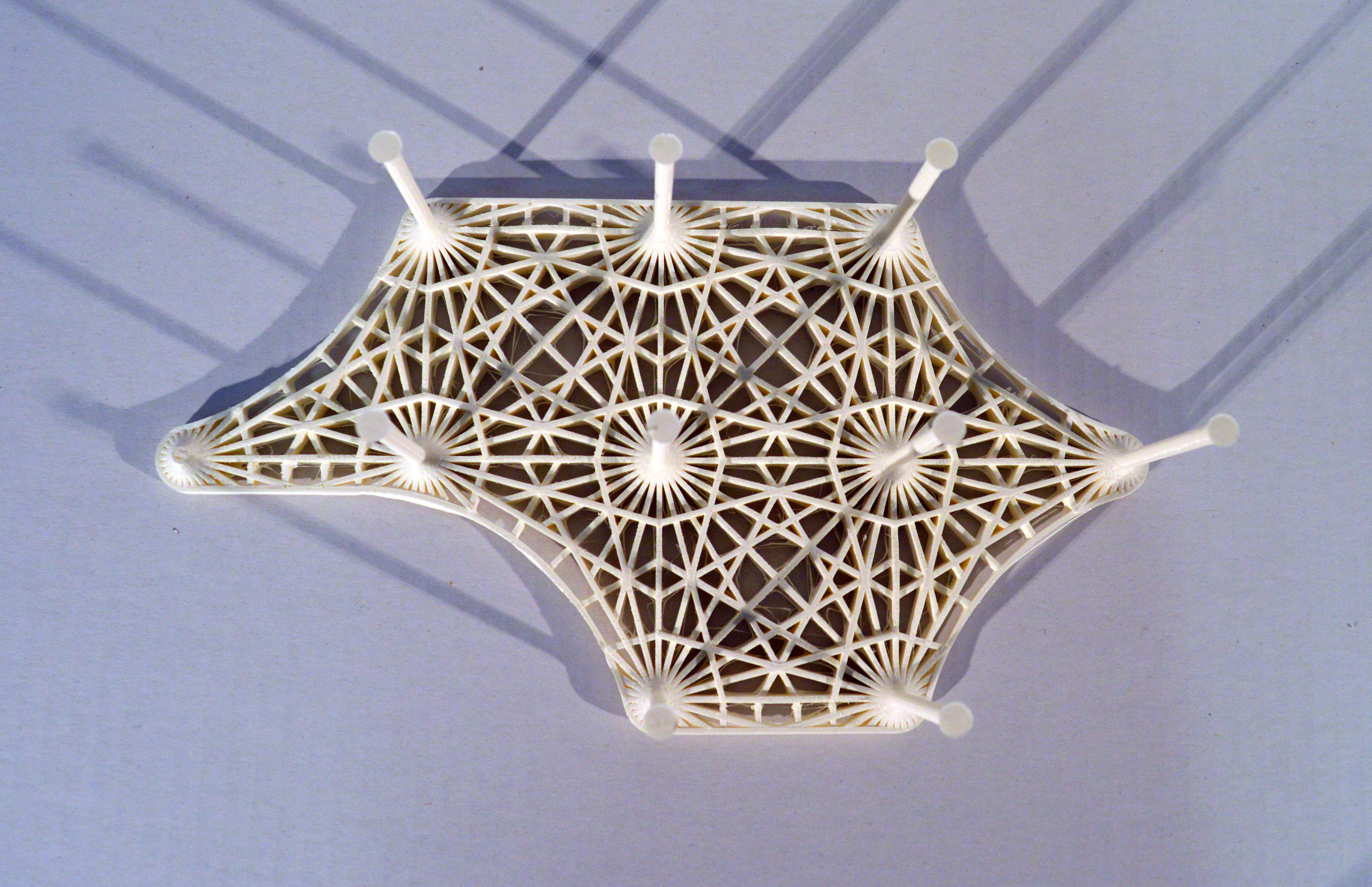
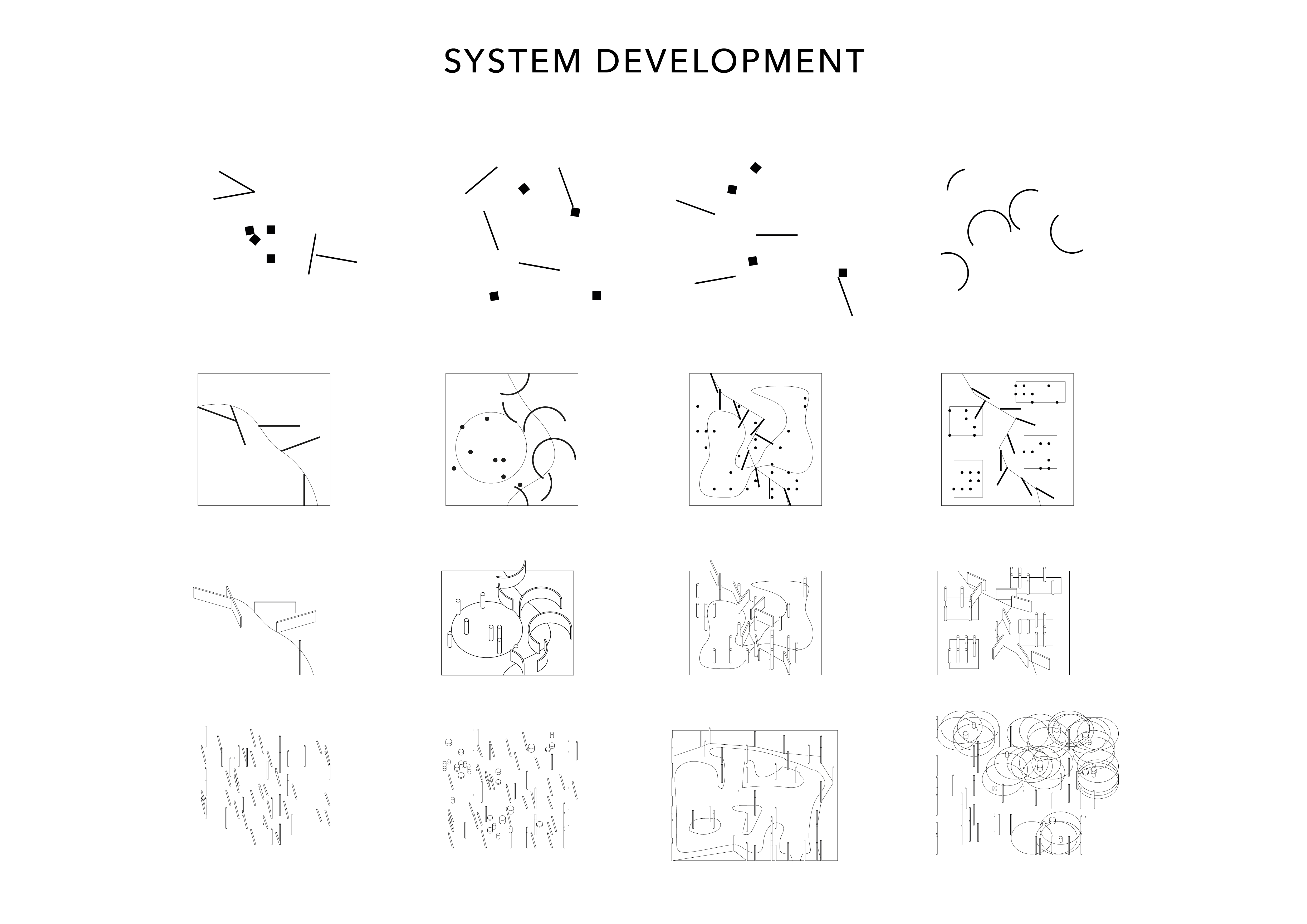
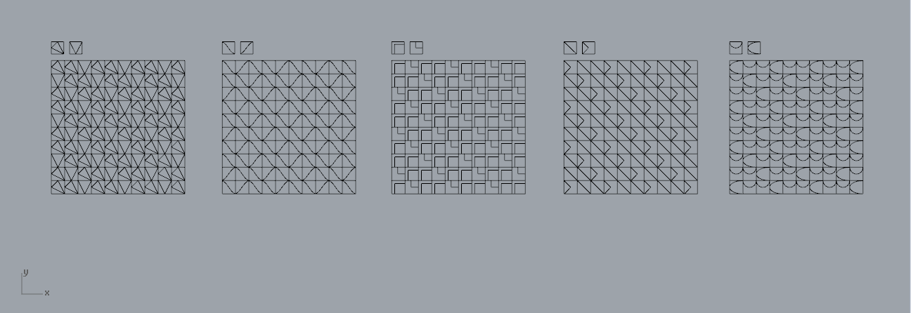
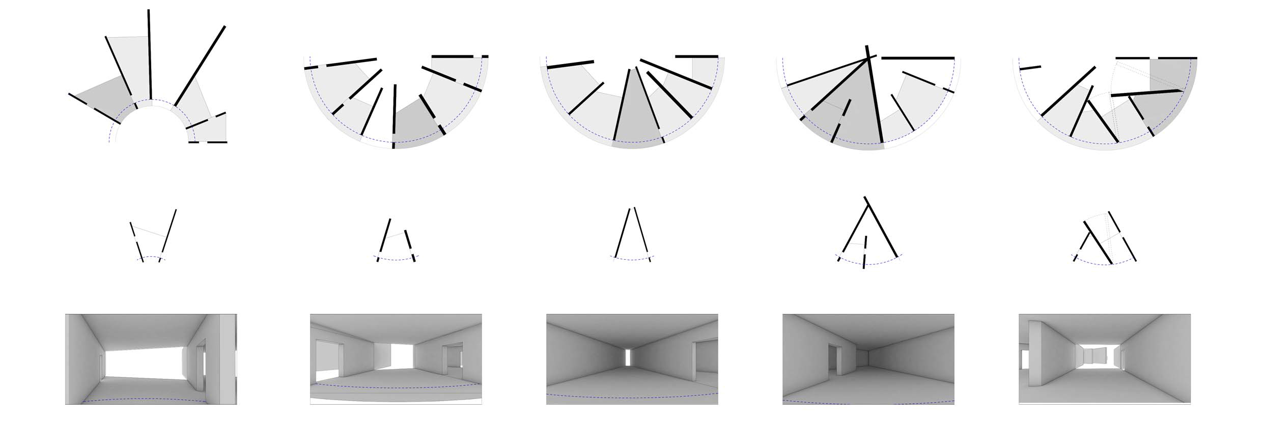
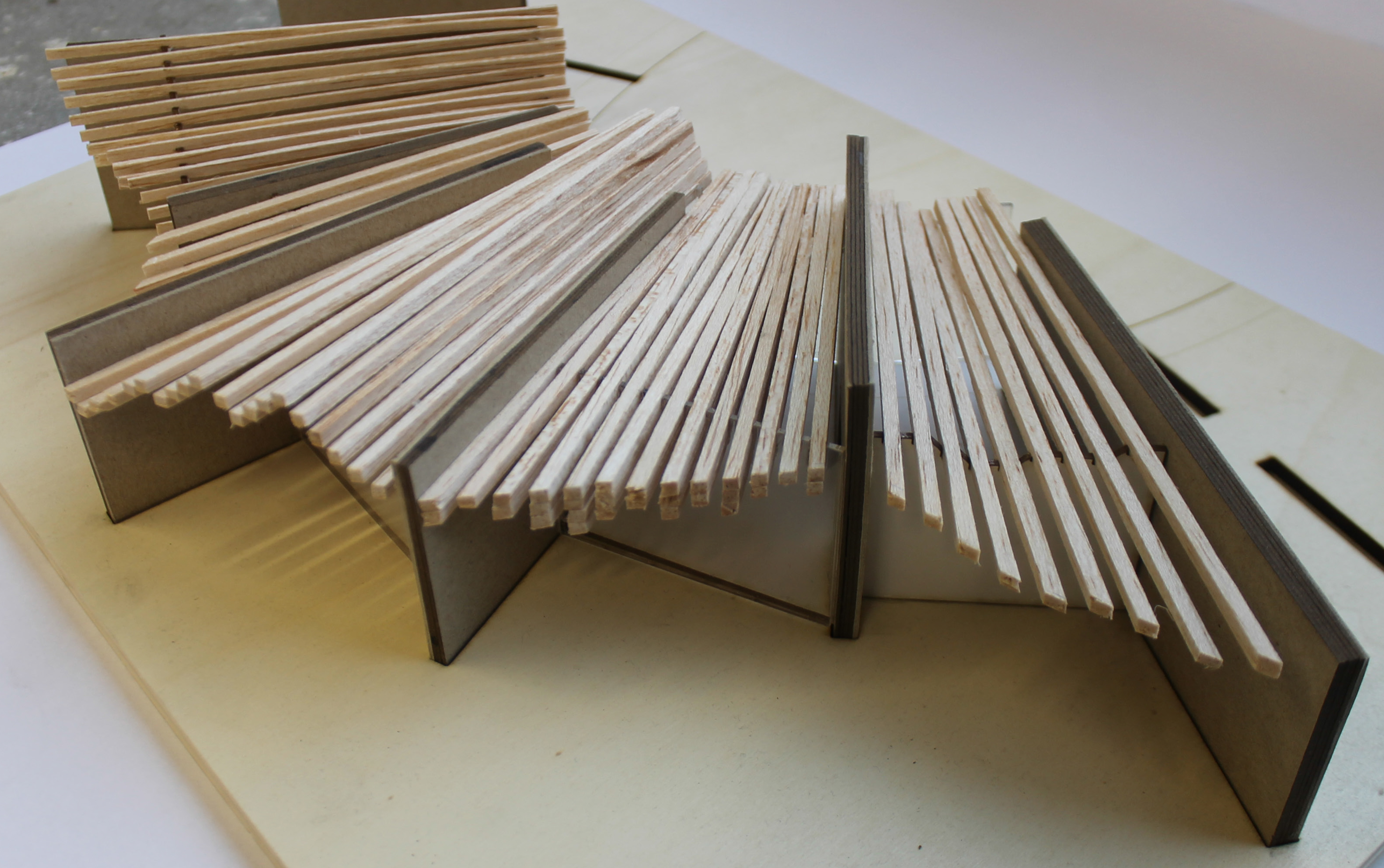
Generating tangents and perpendiculars

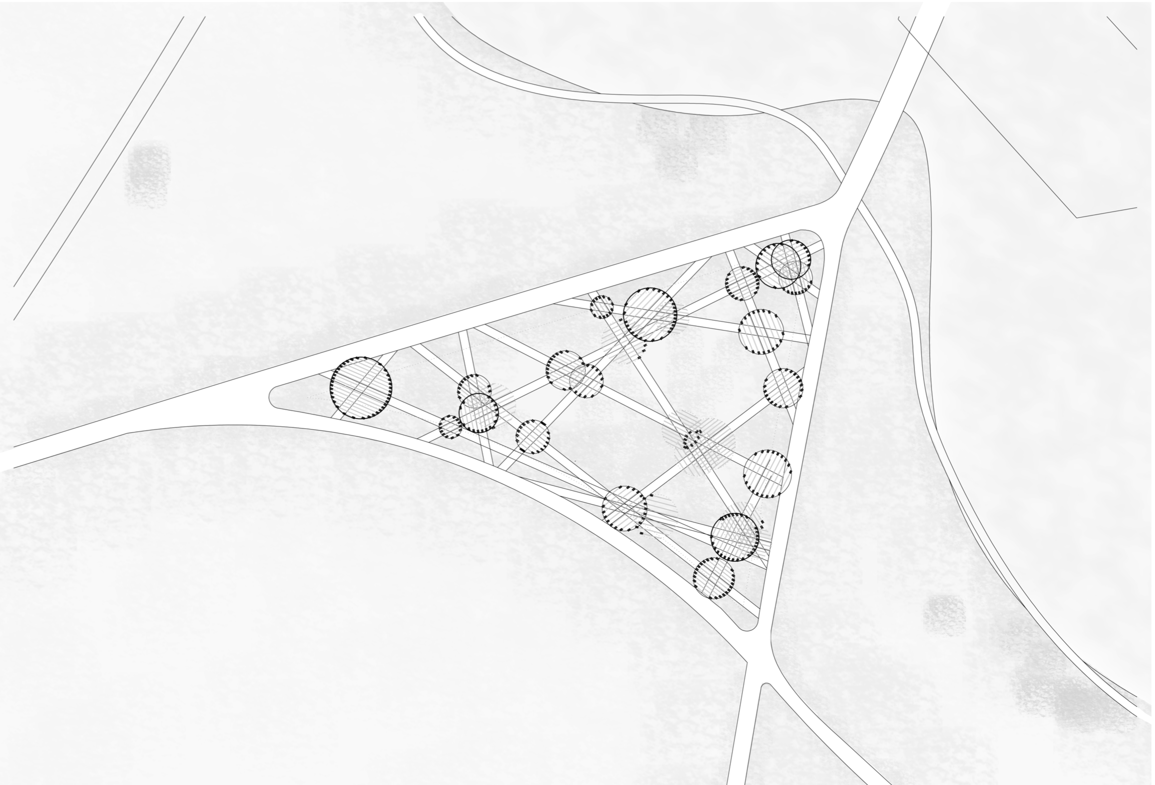
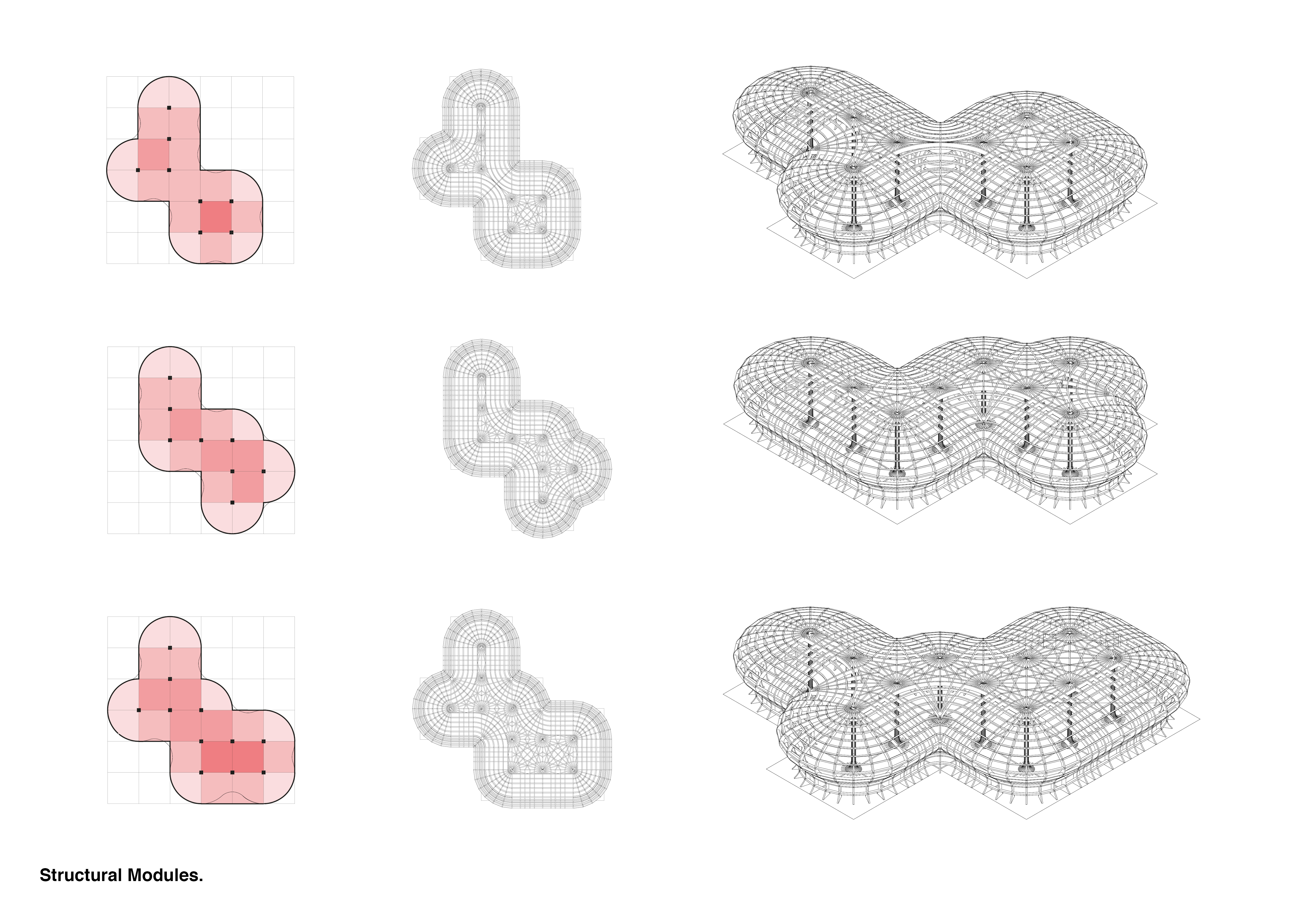
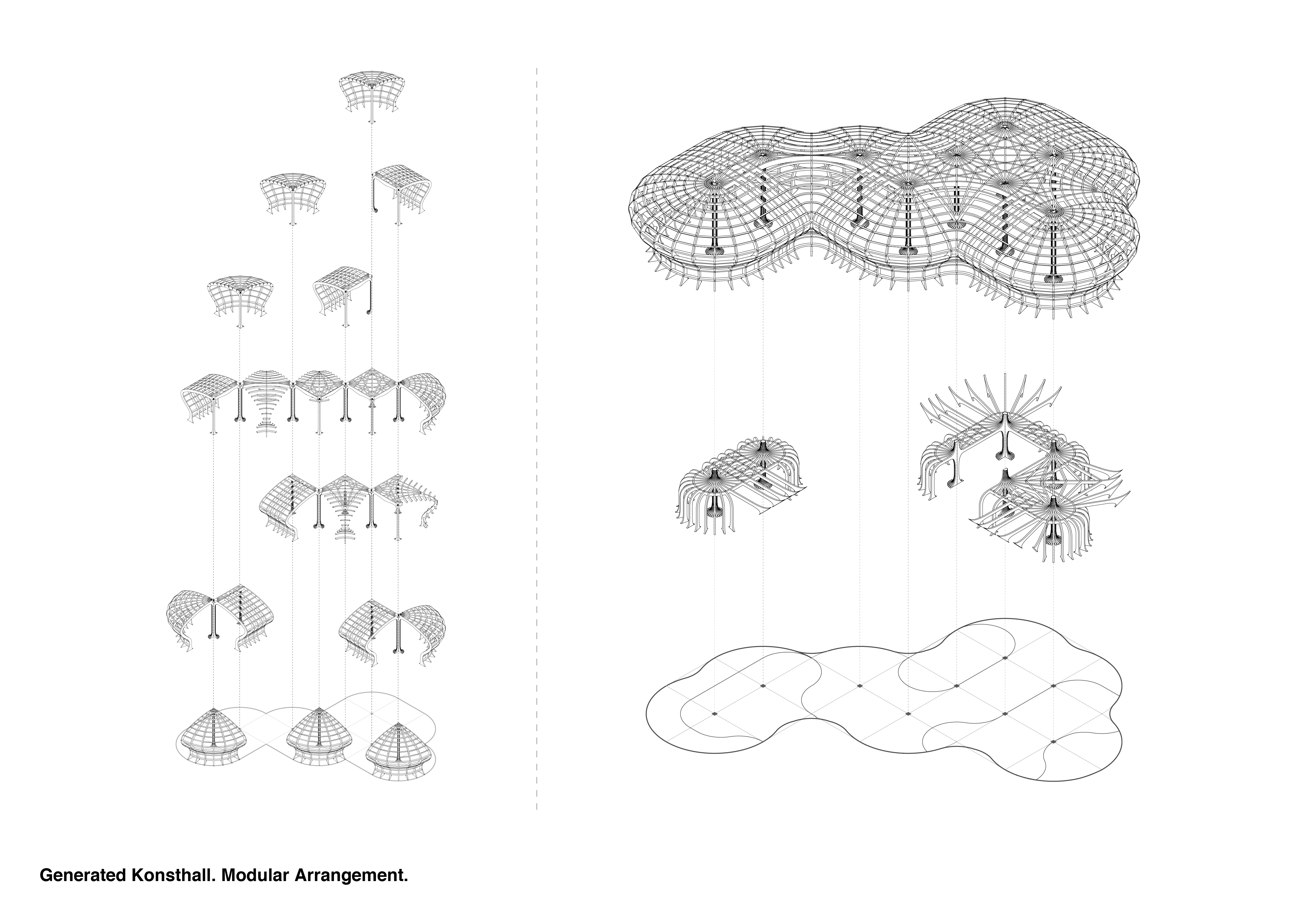
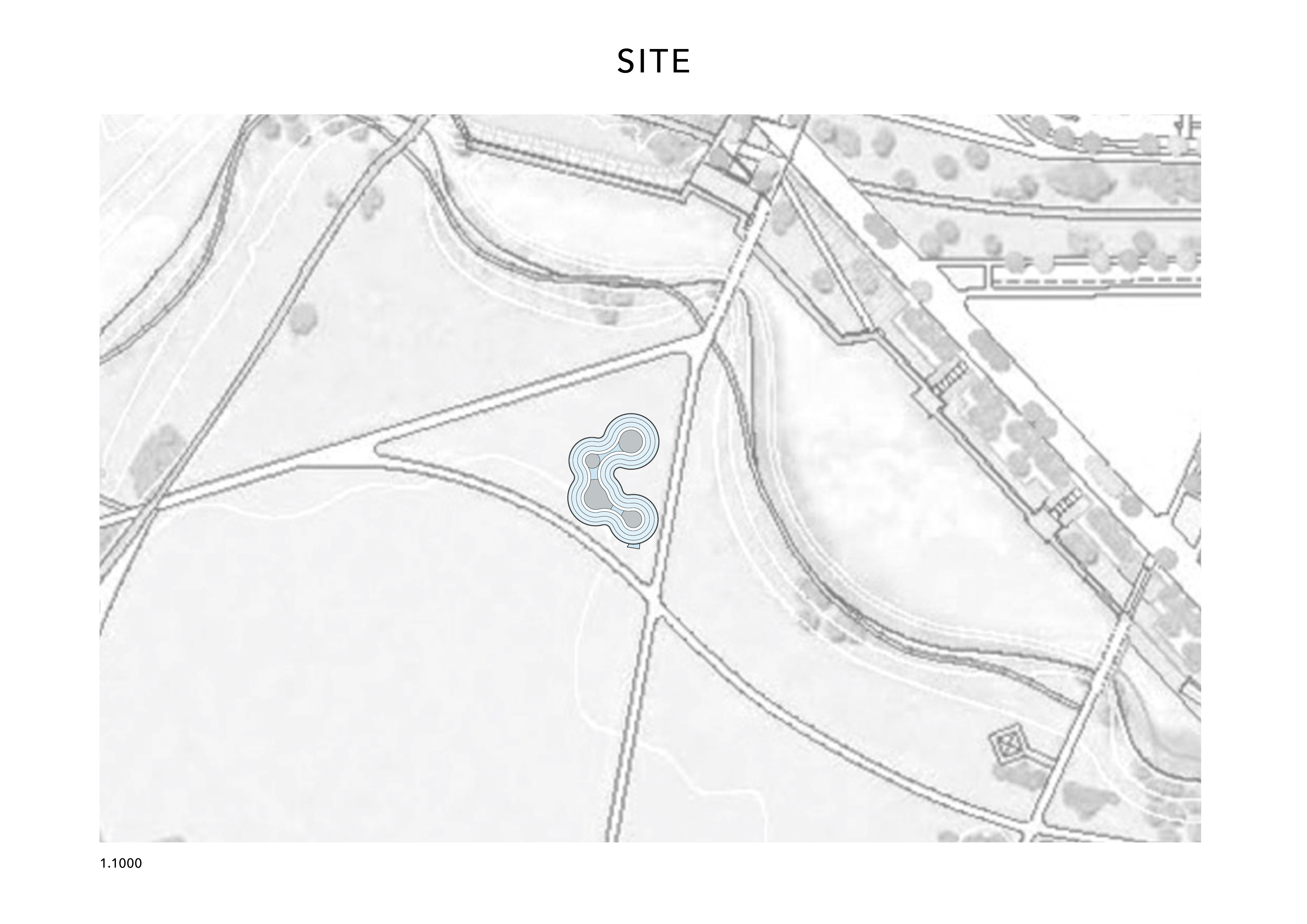
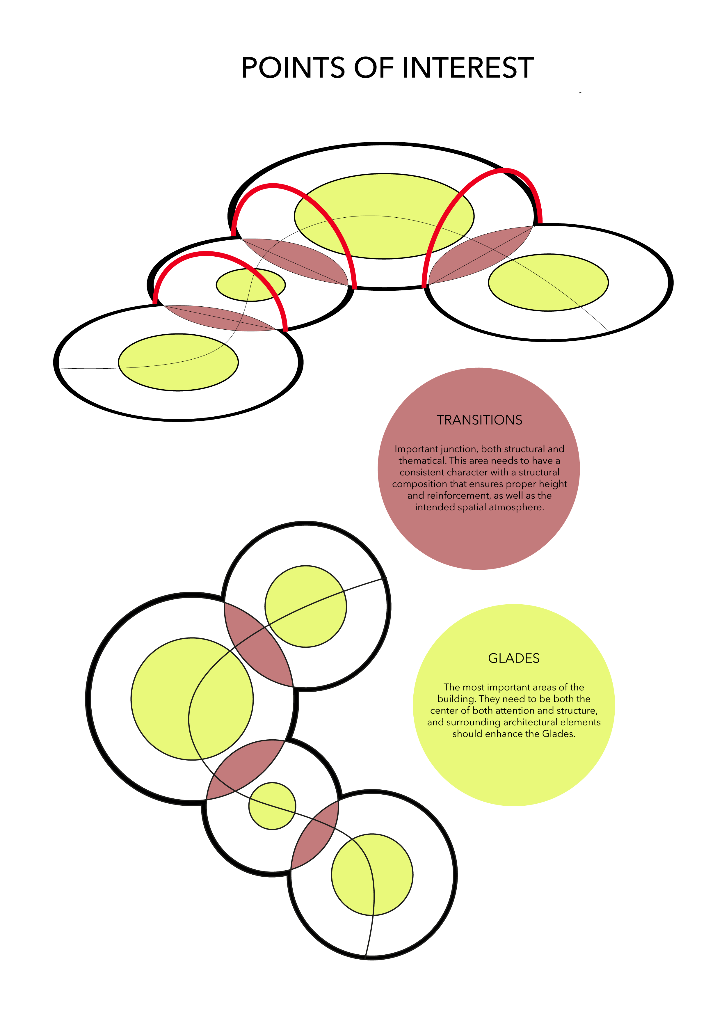
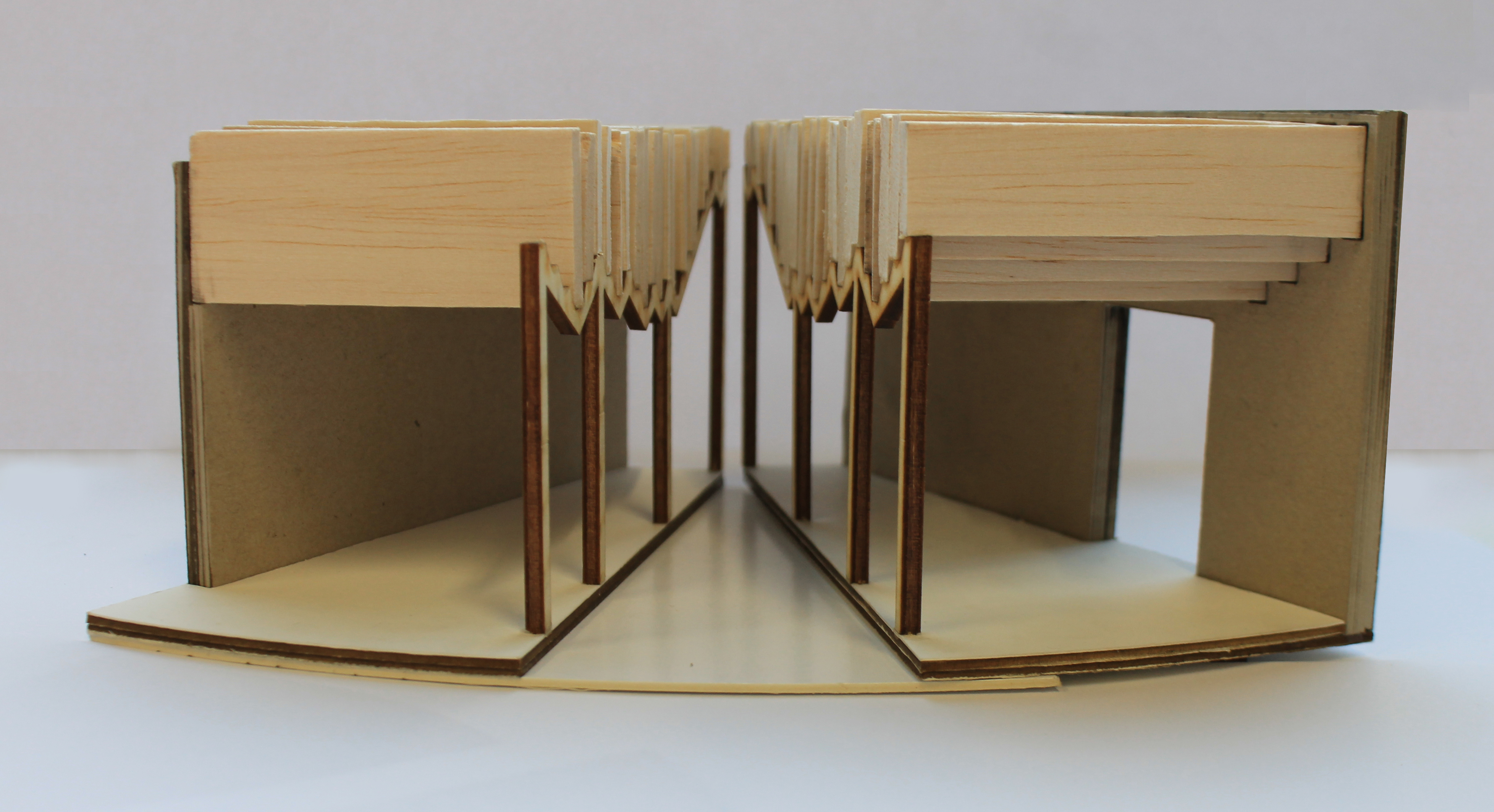
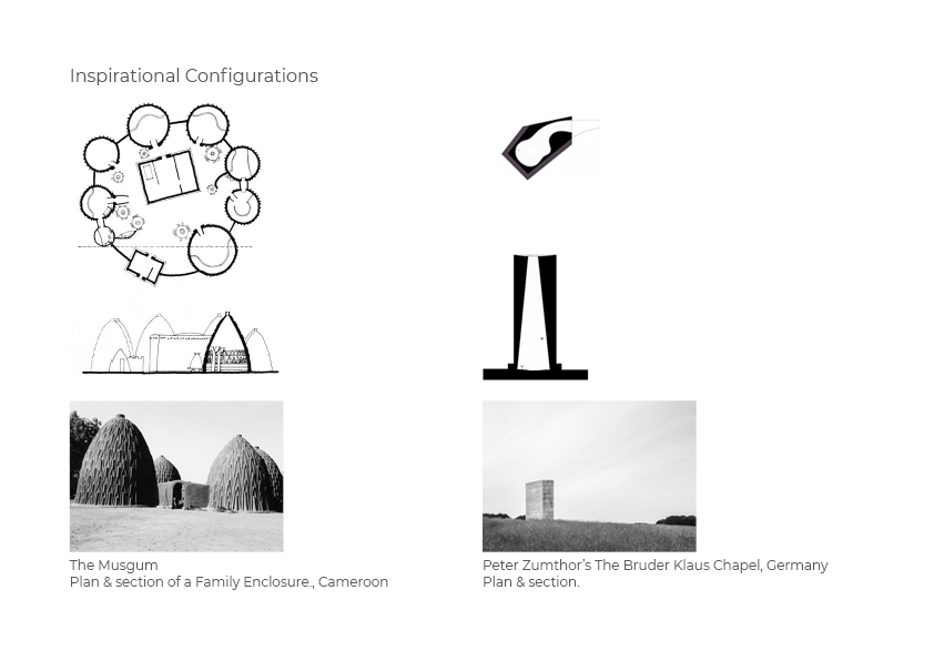
Organisation and arrangements

3

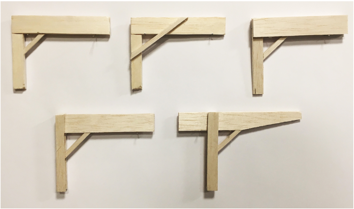
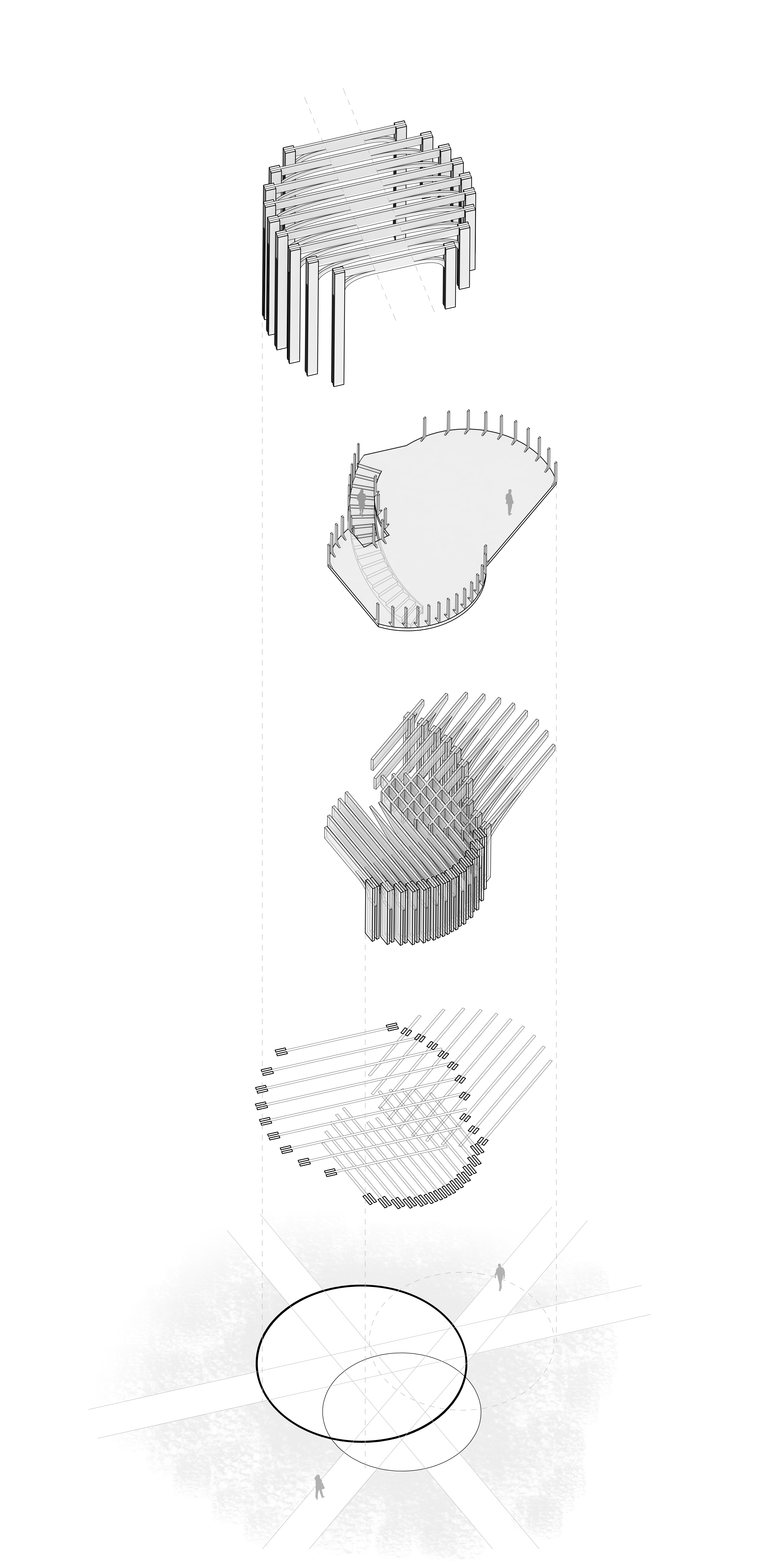
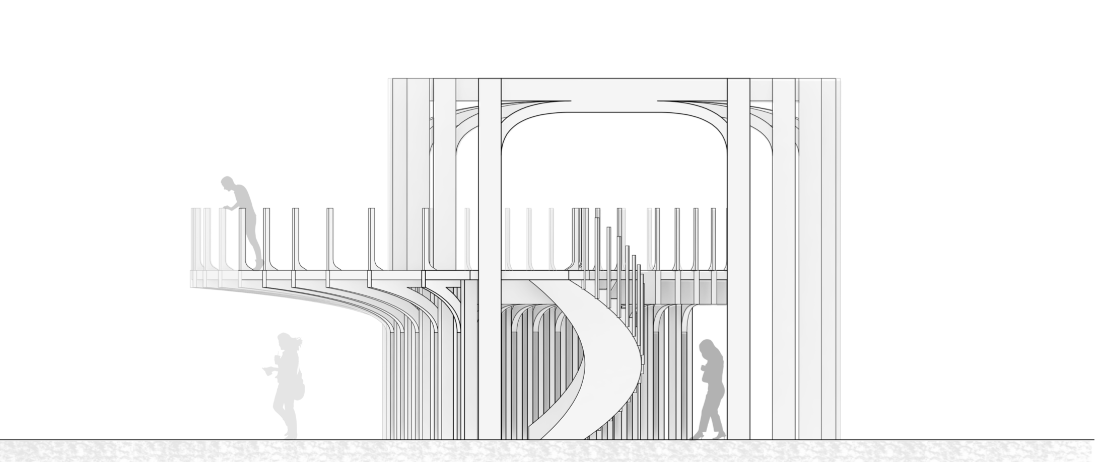
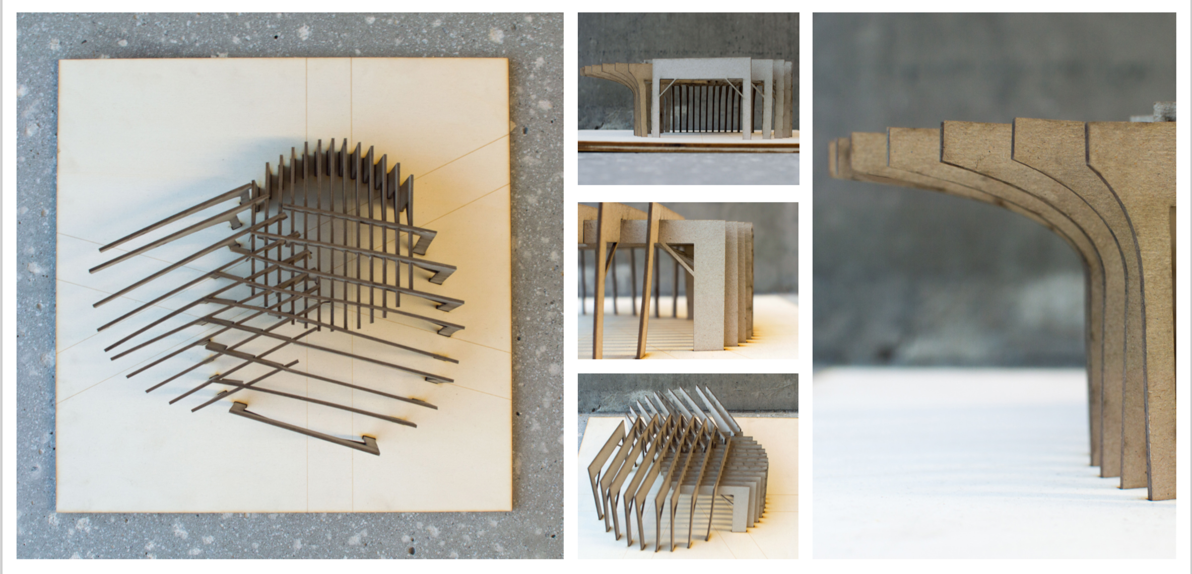
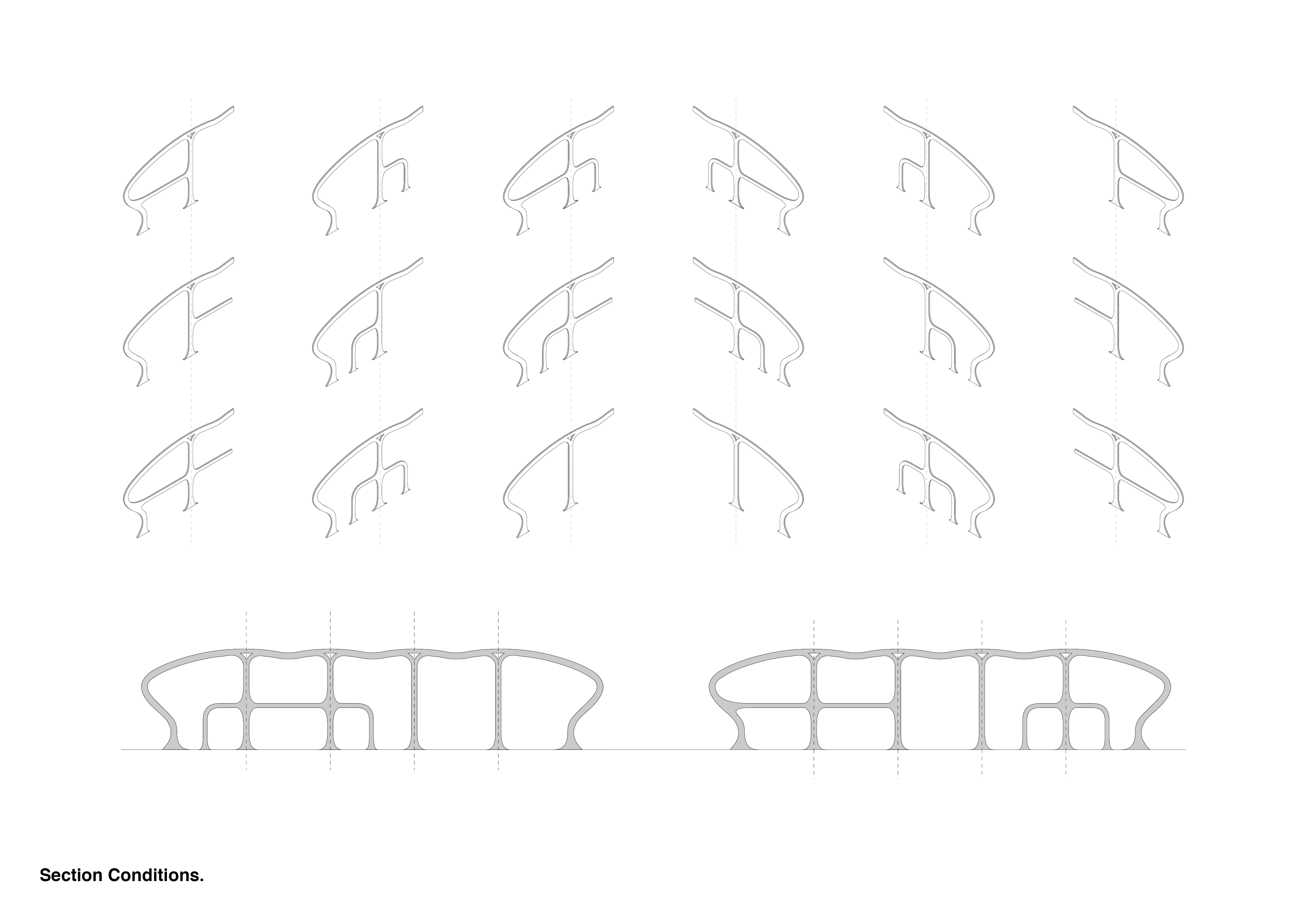
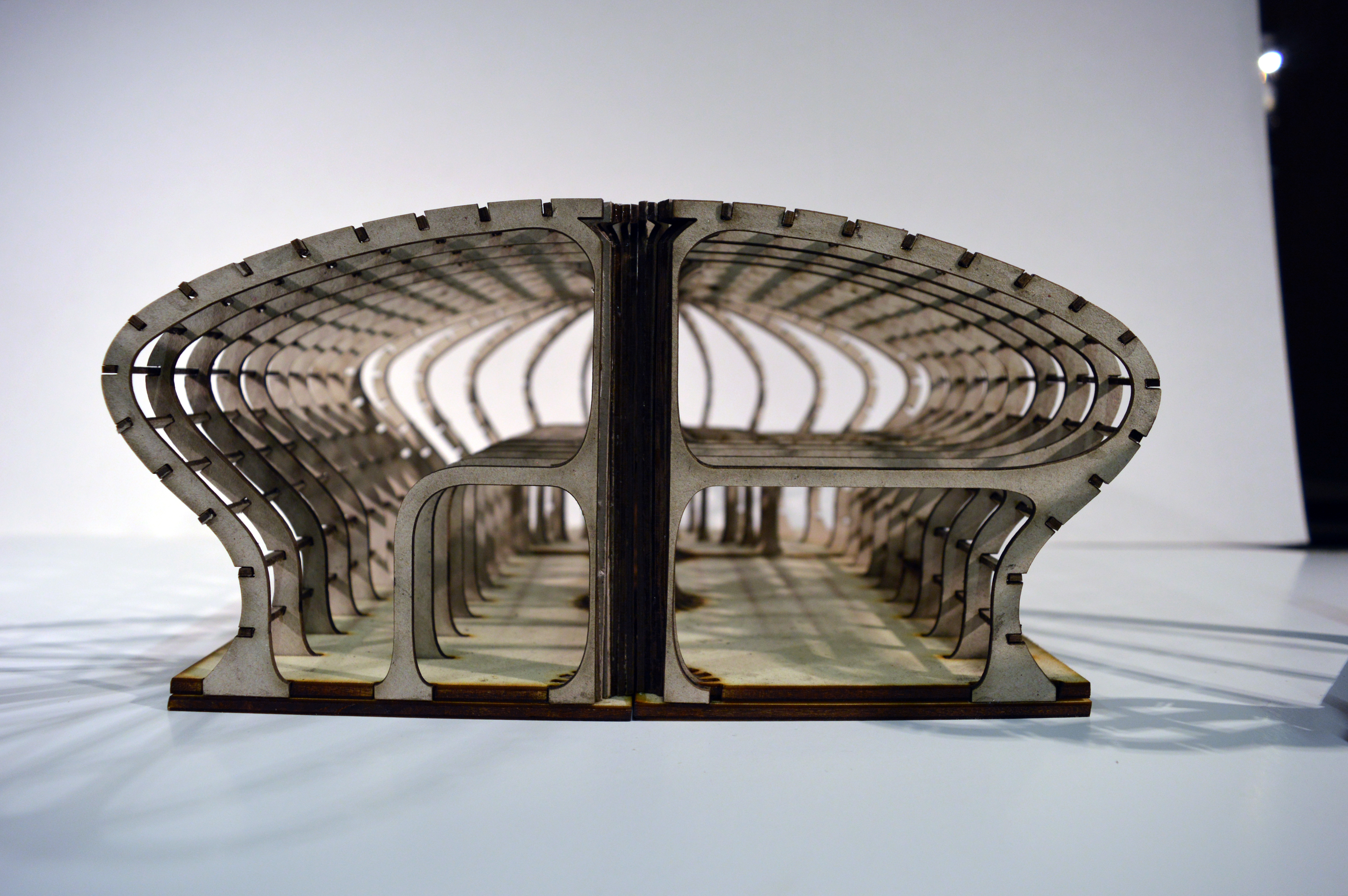
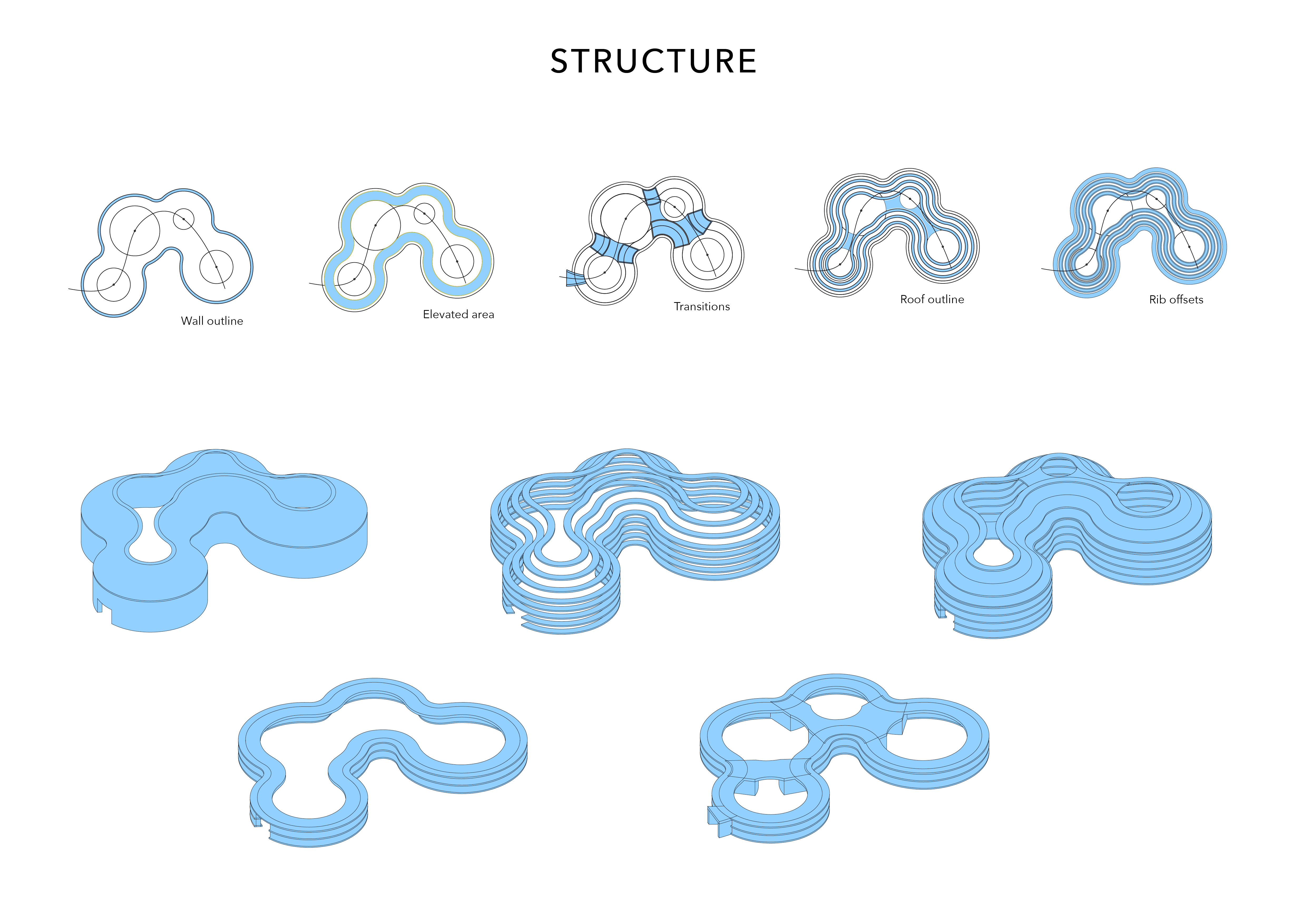
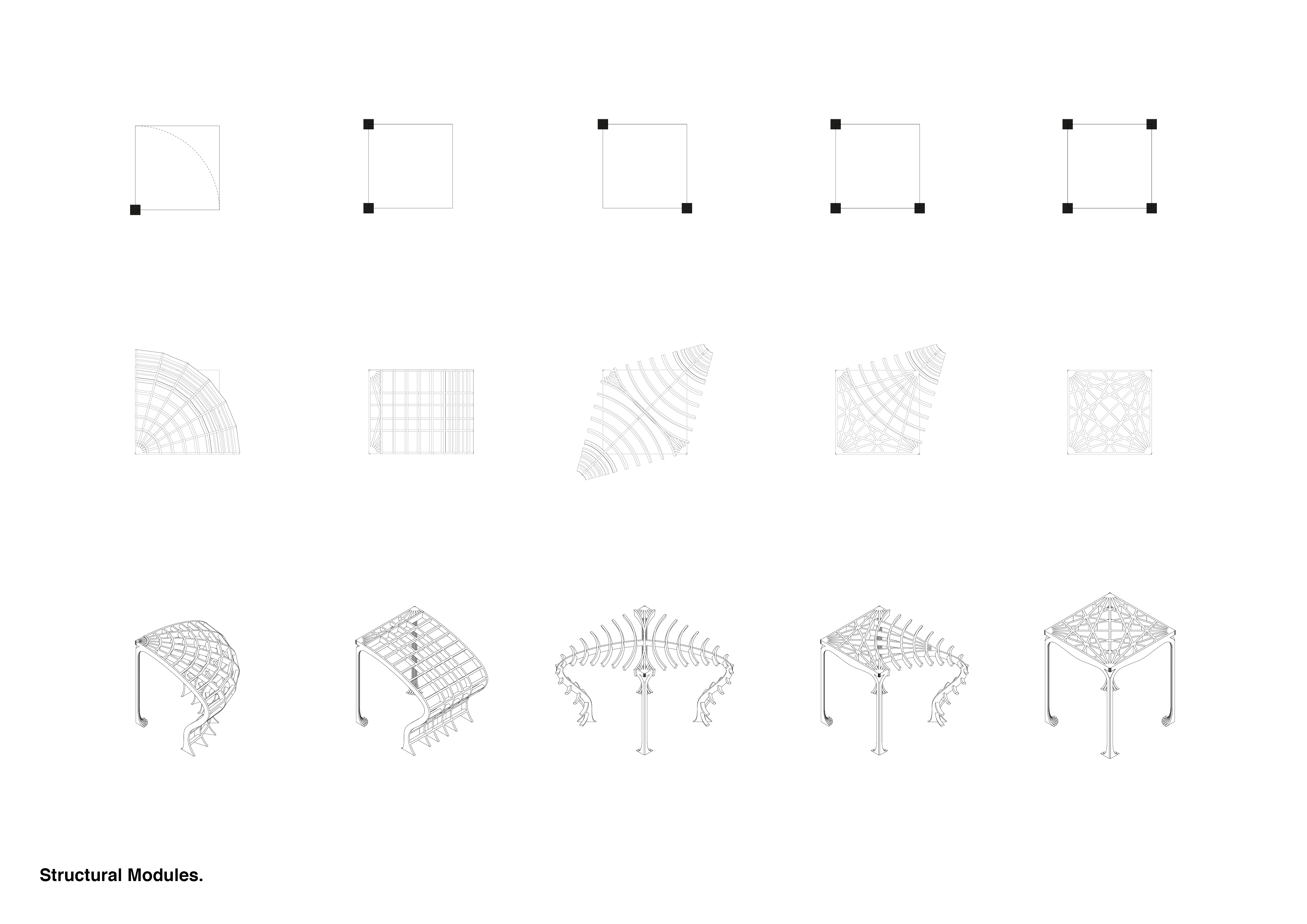
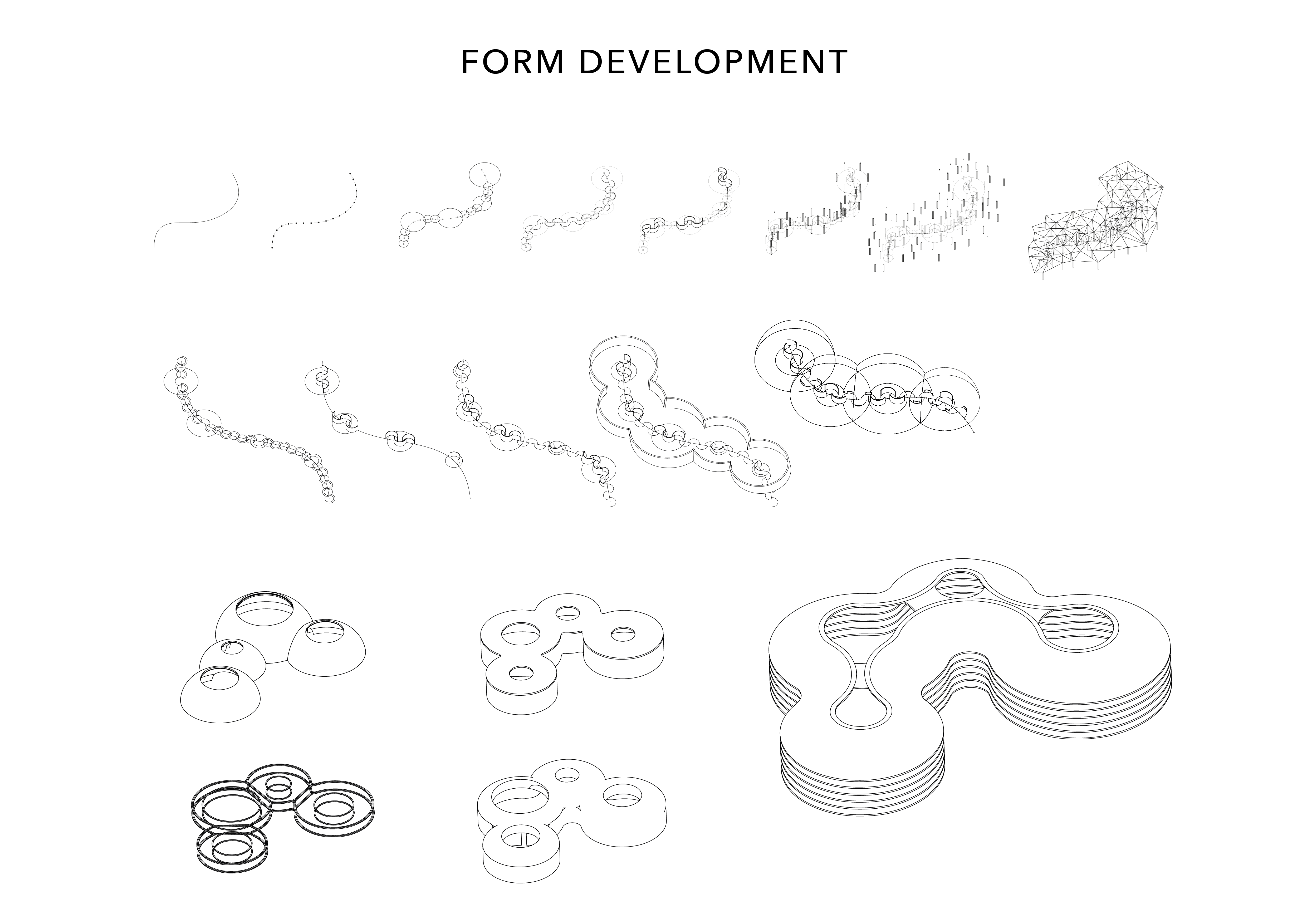
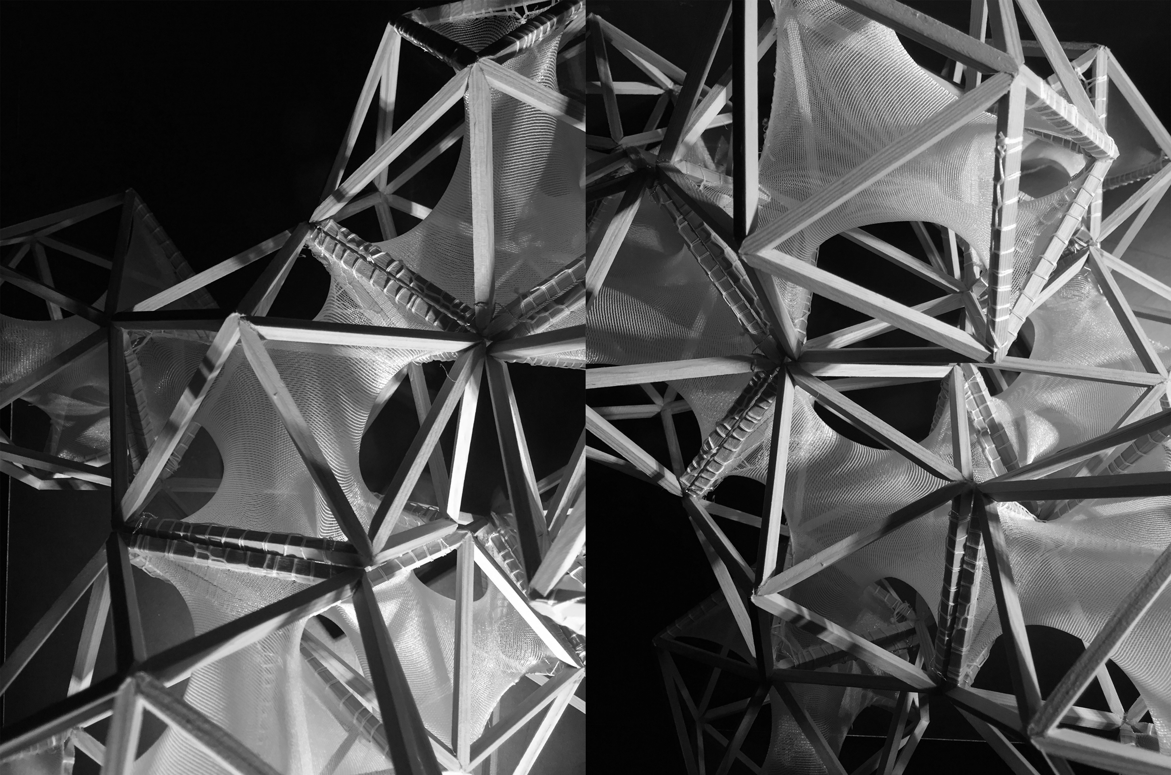
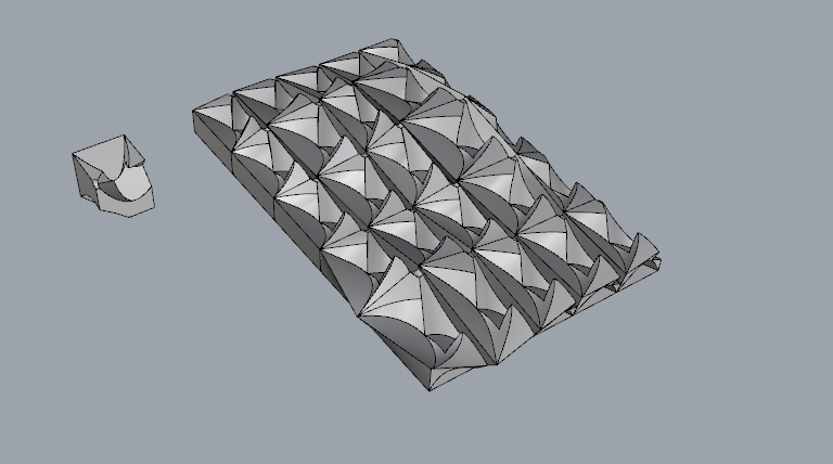
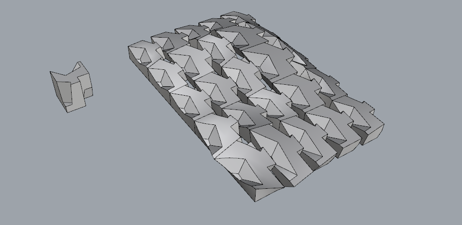
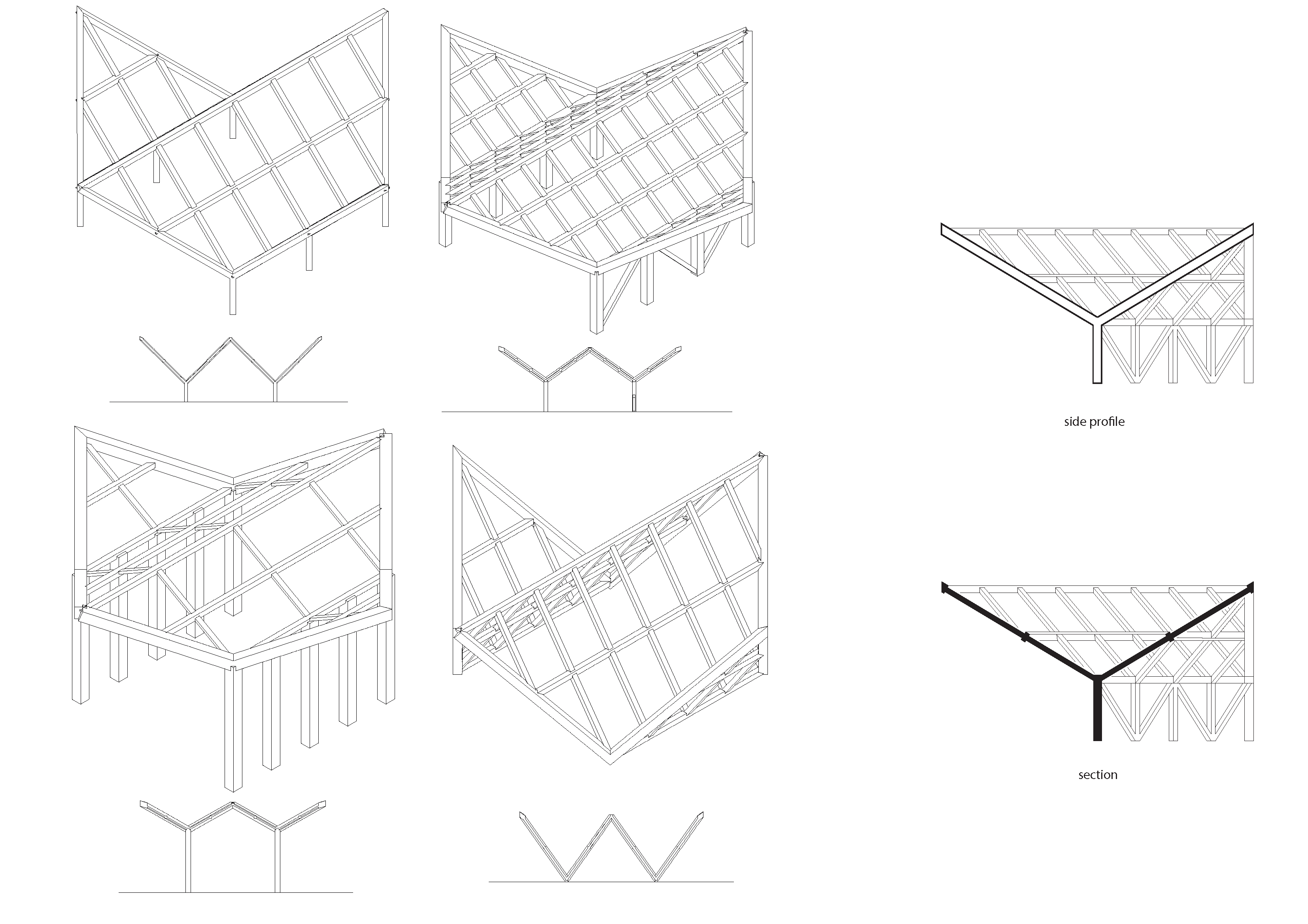
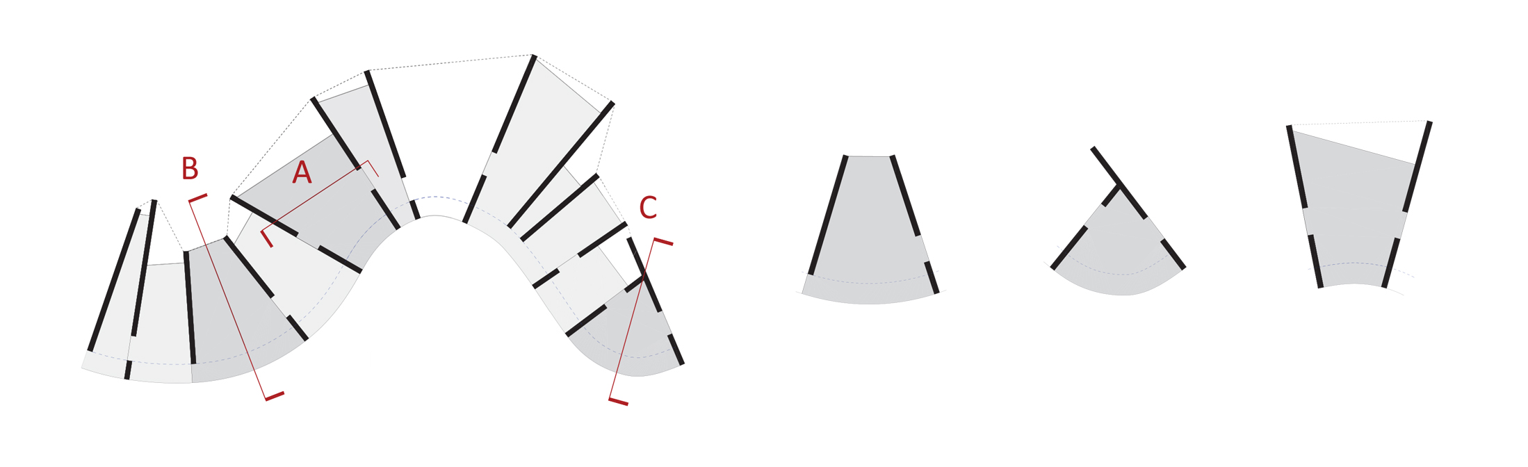
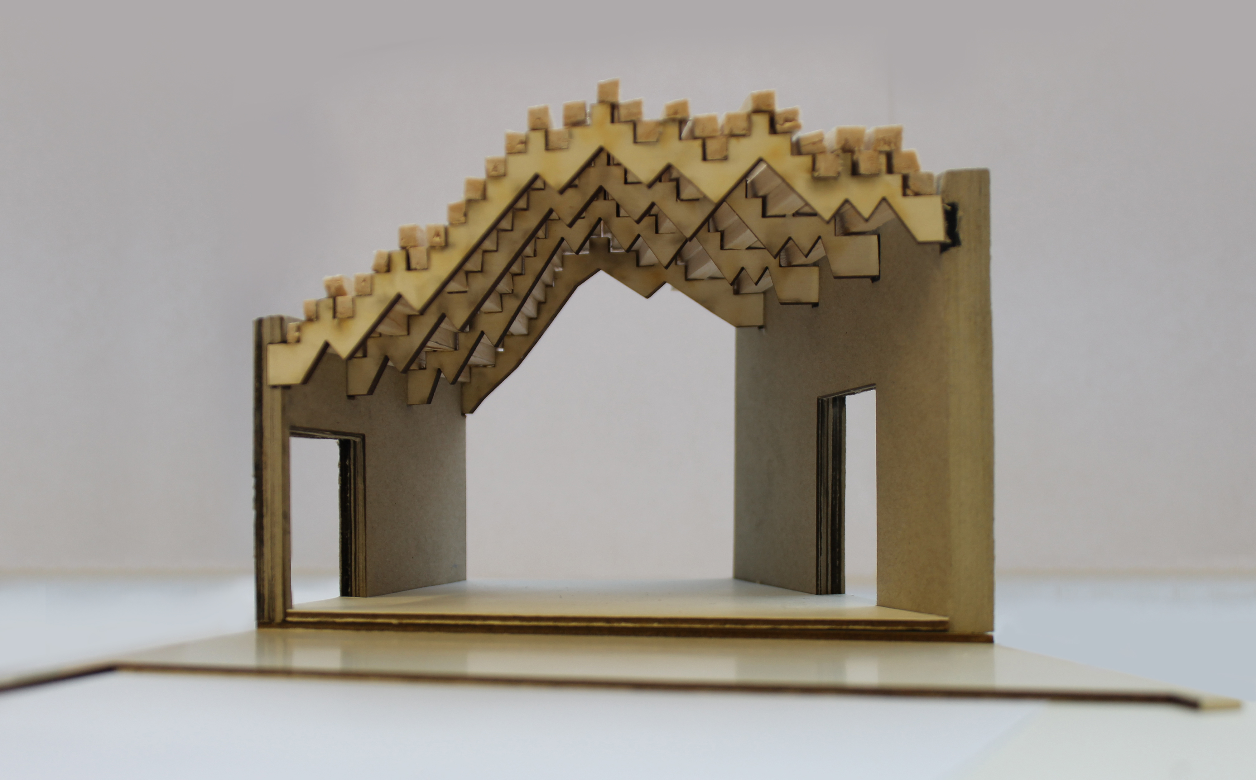
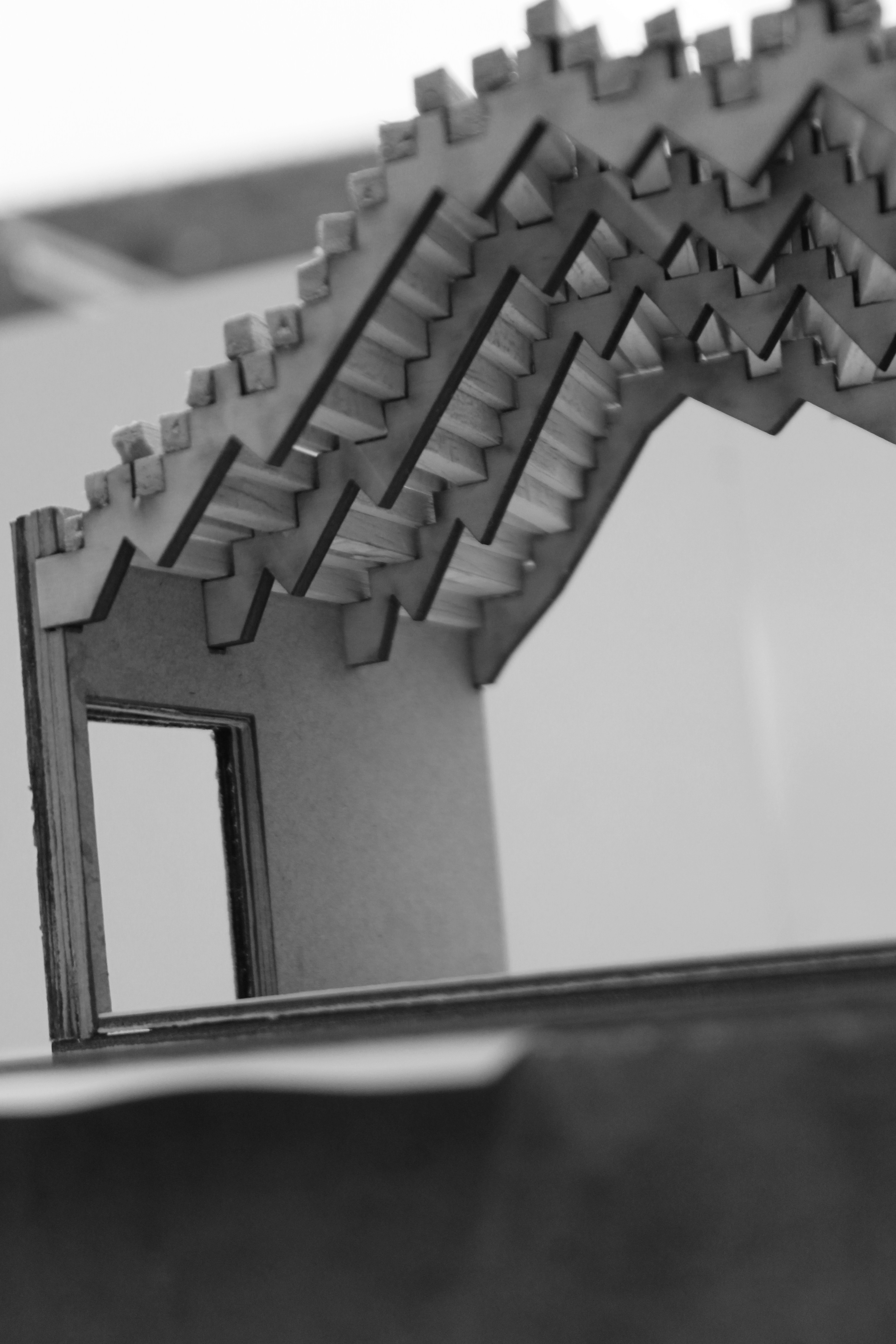
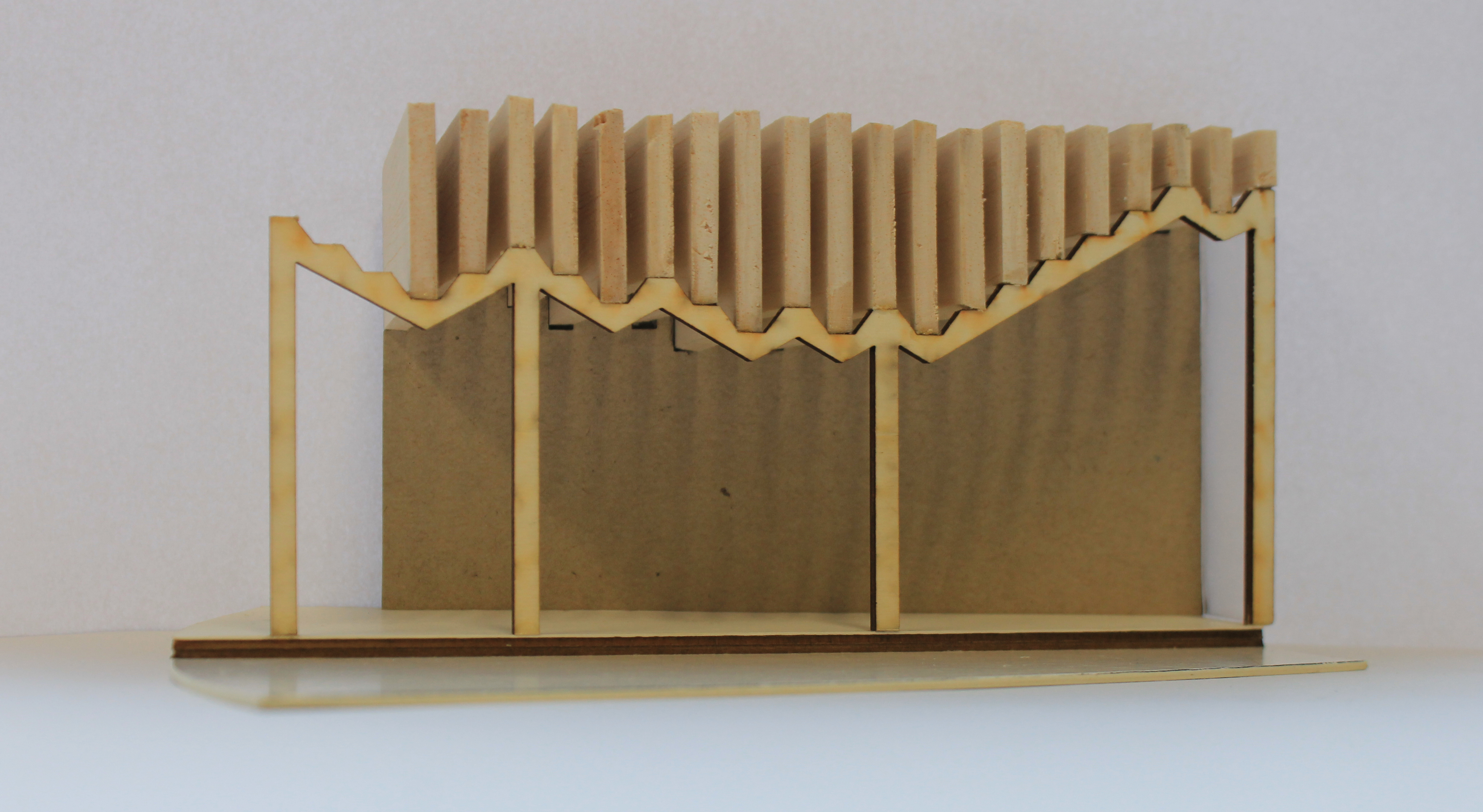
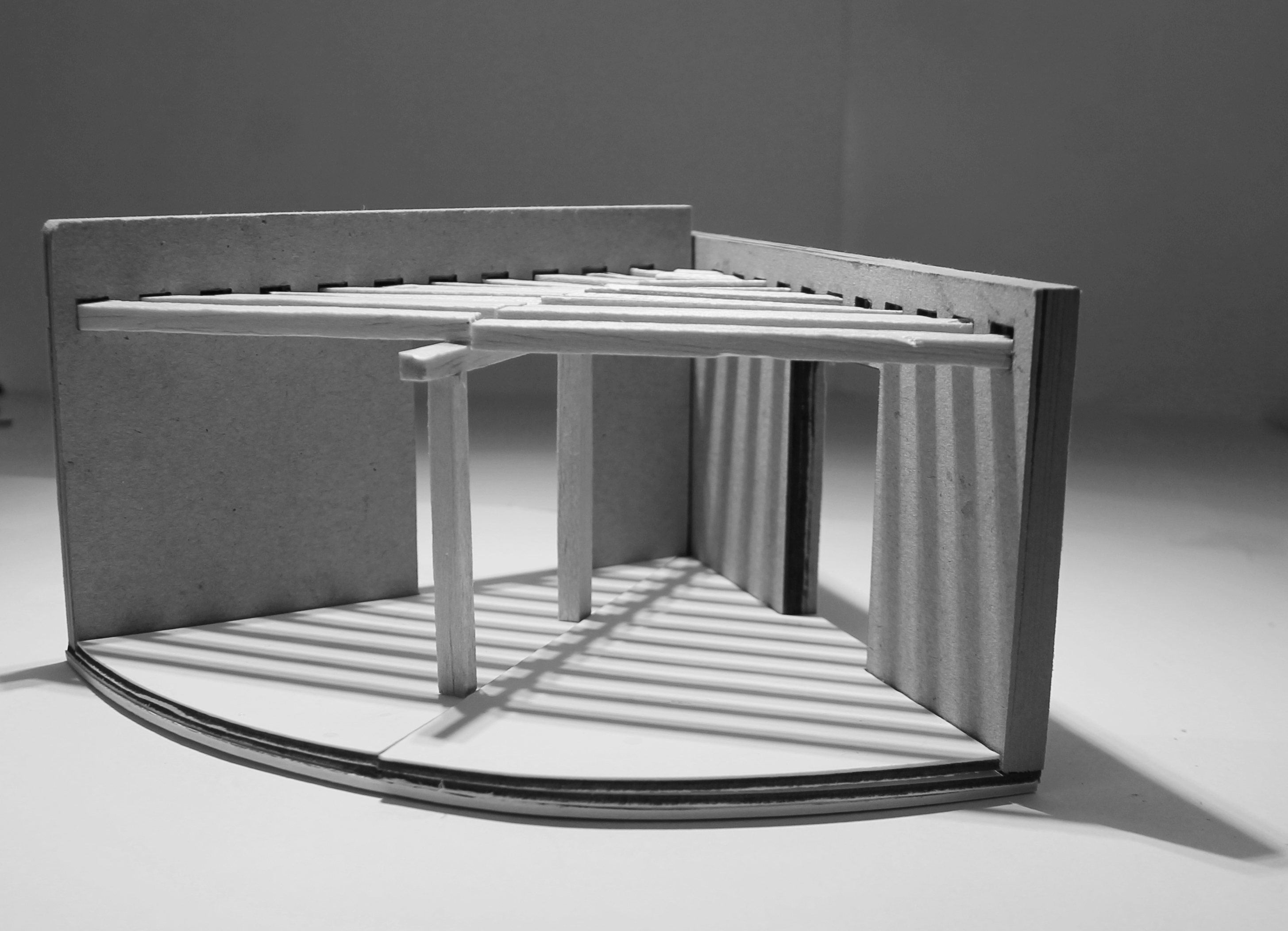
Extrapolating the geometry into structure

4

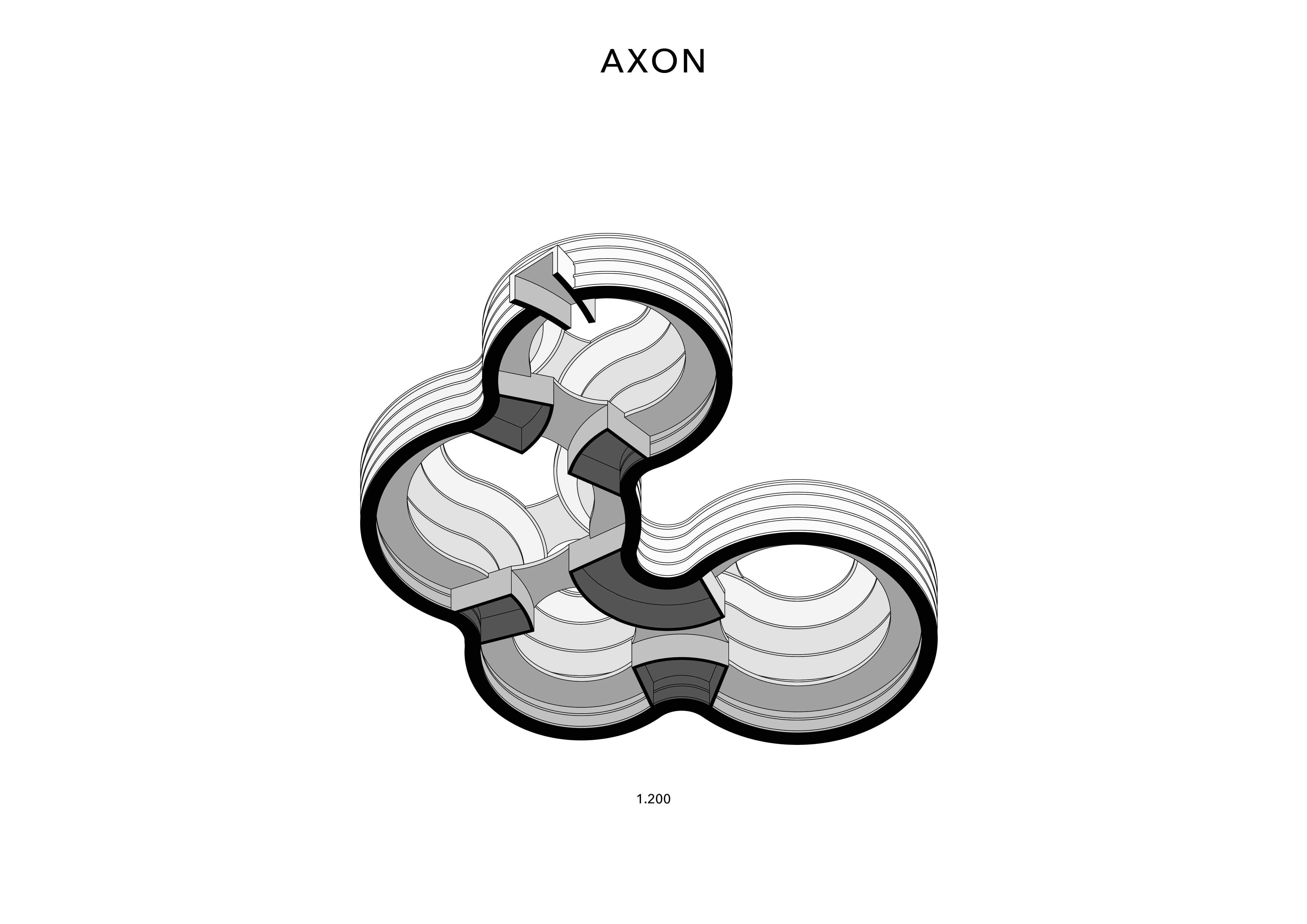
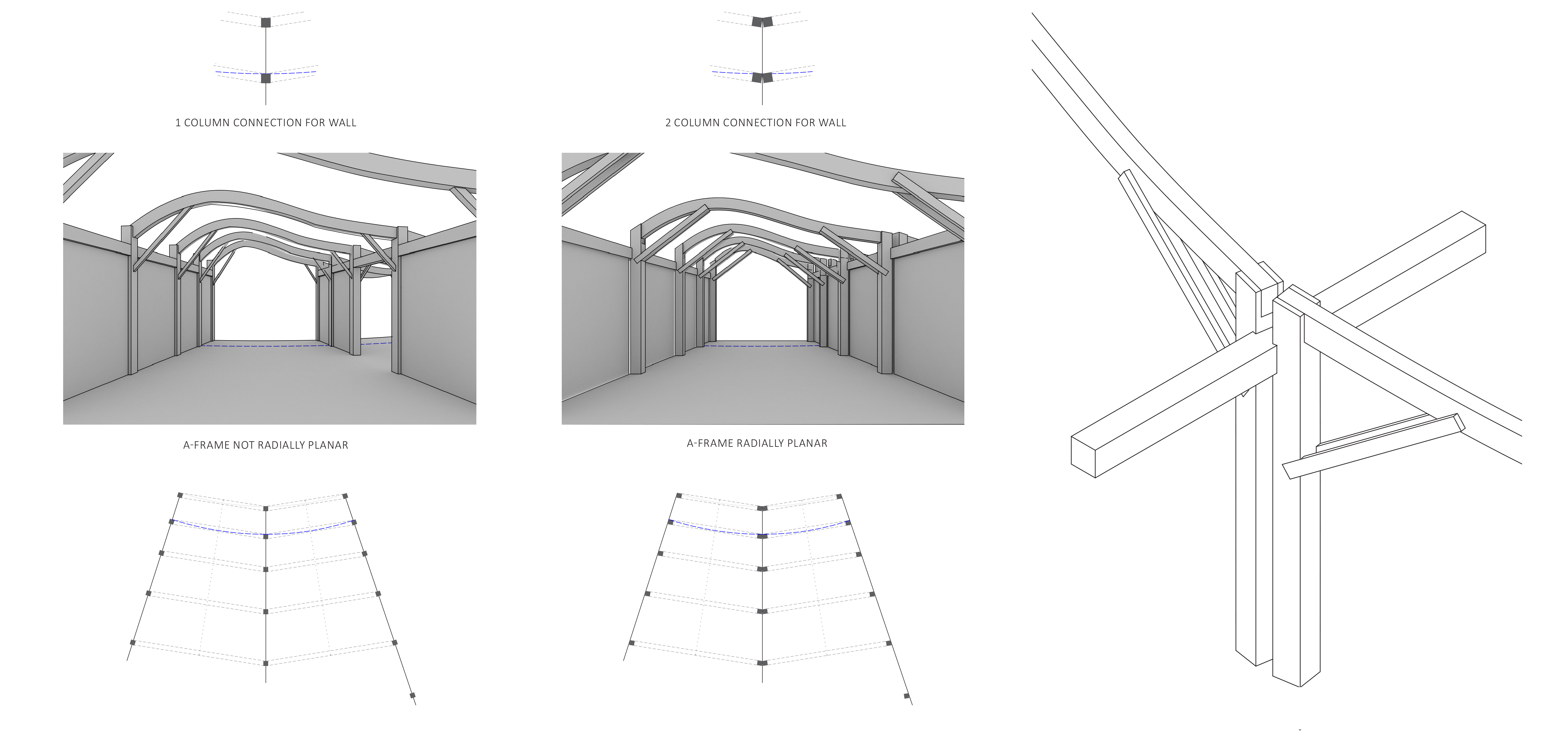
Development Axonometric – Three systems meeting – Walls, beams and roof

7

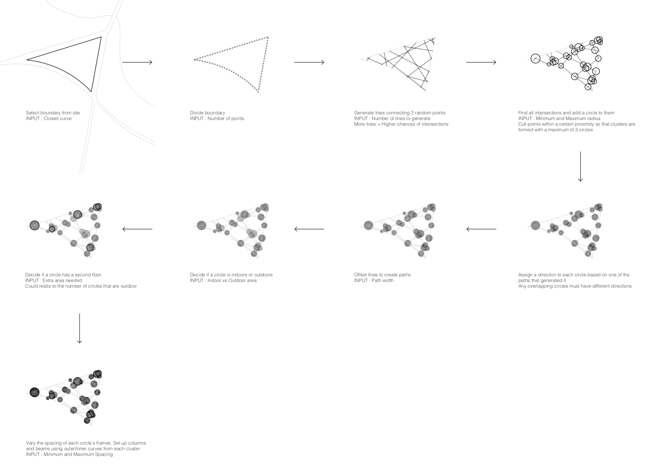
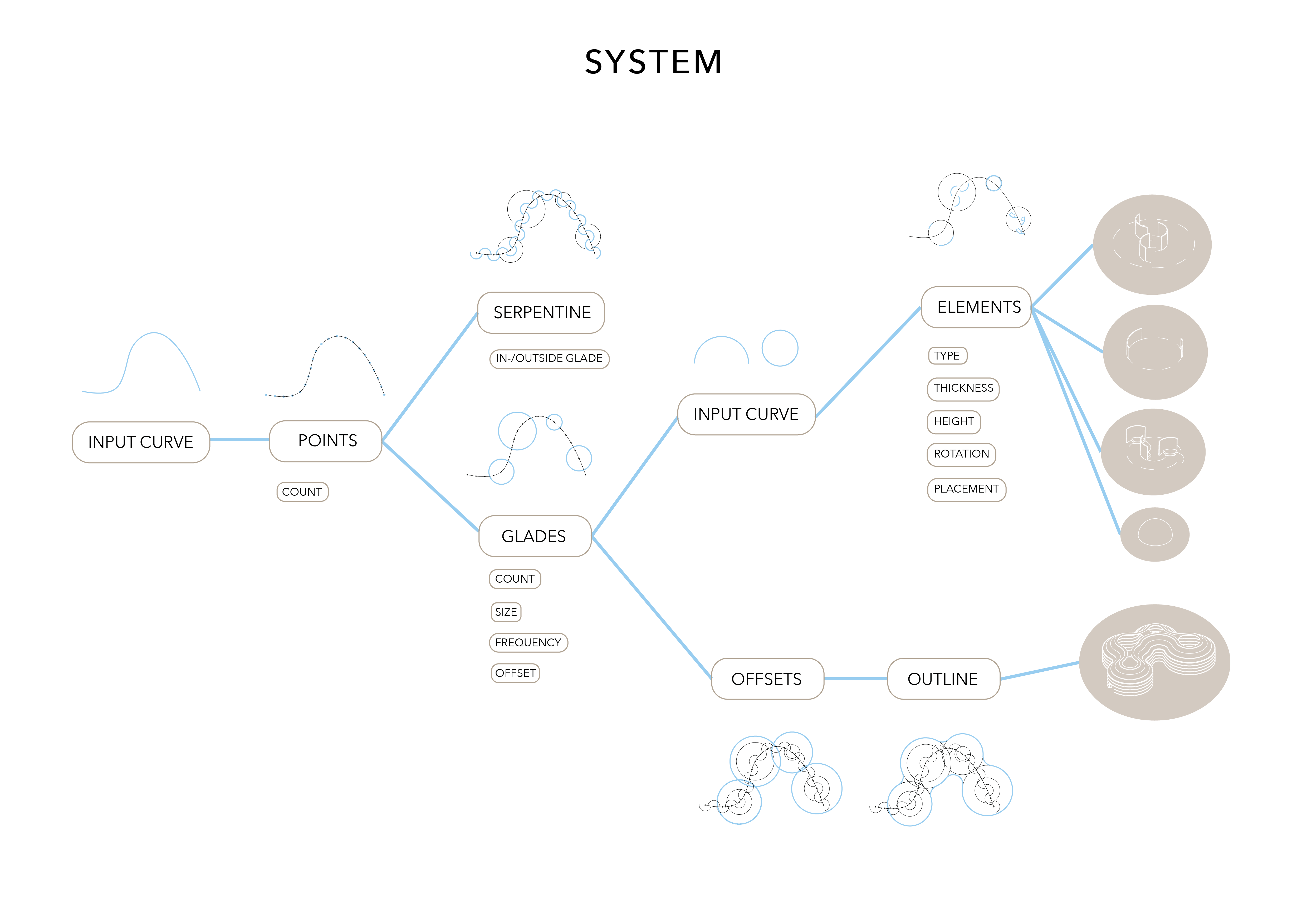
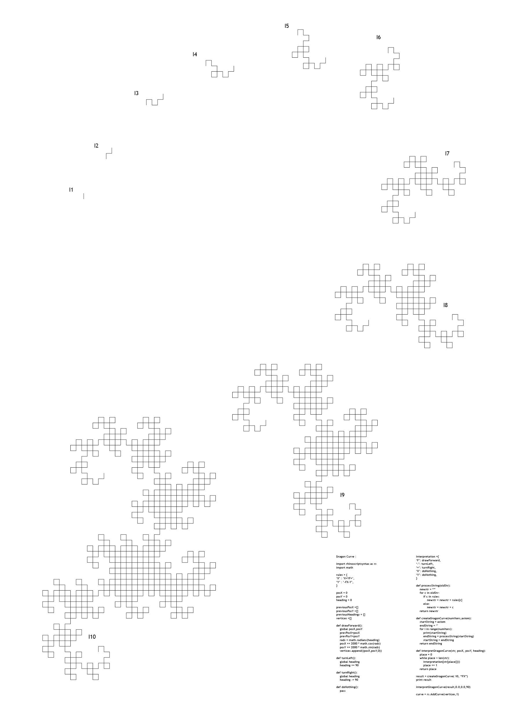
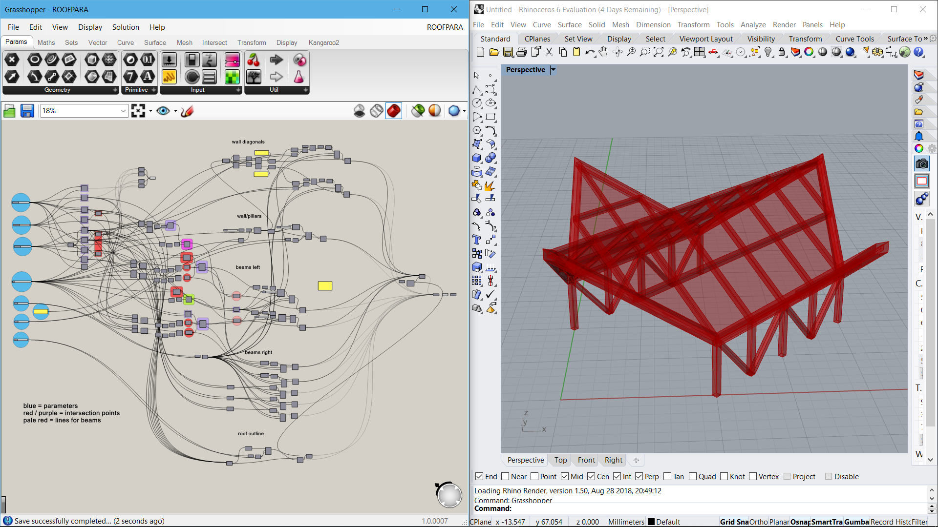
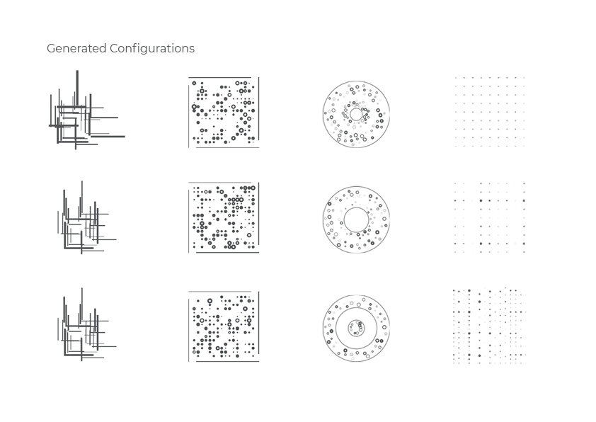
Python System Breakdown

8

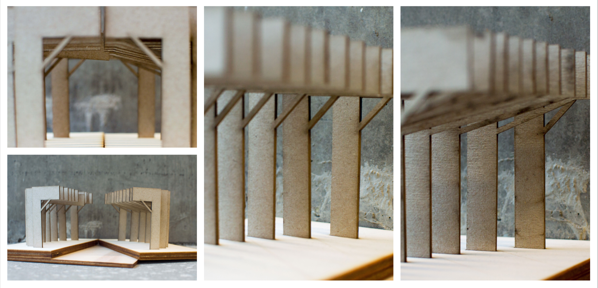
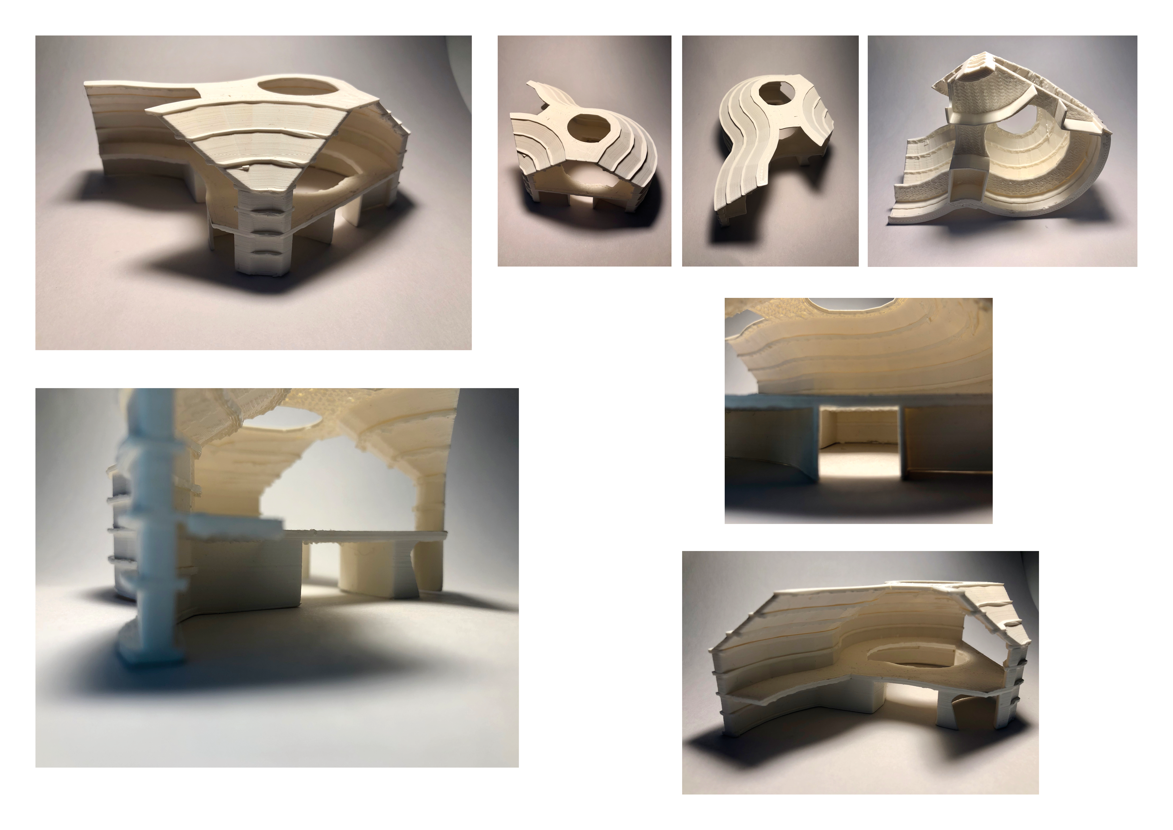
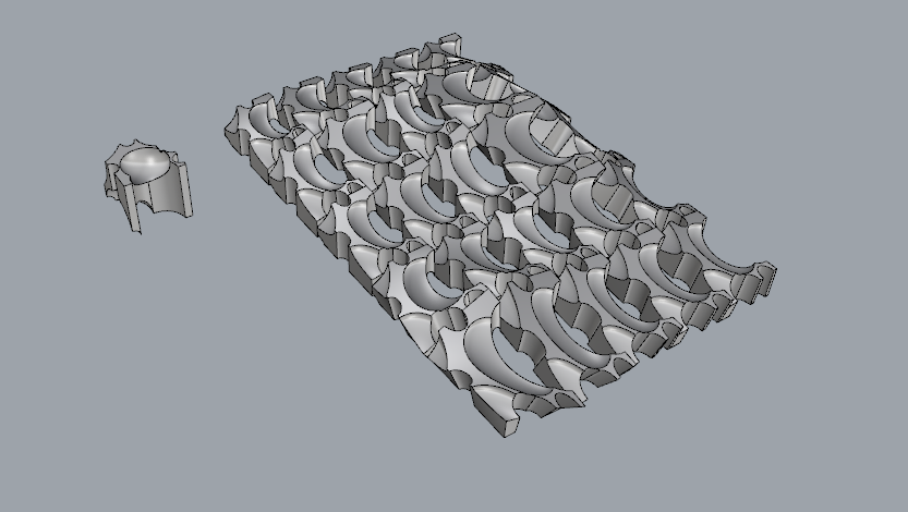
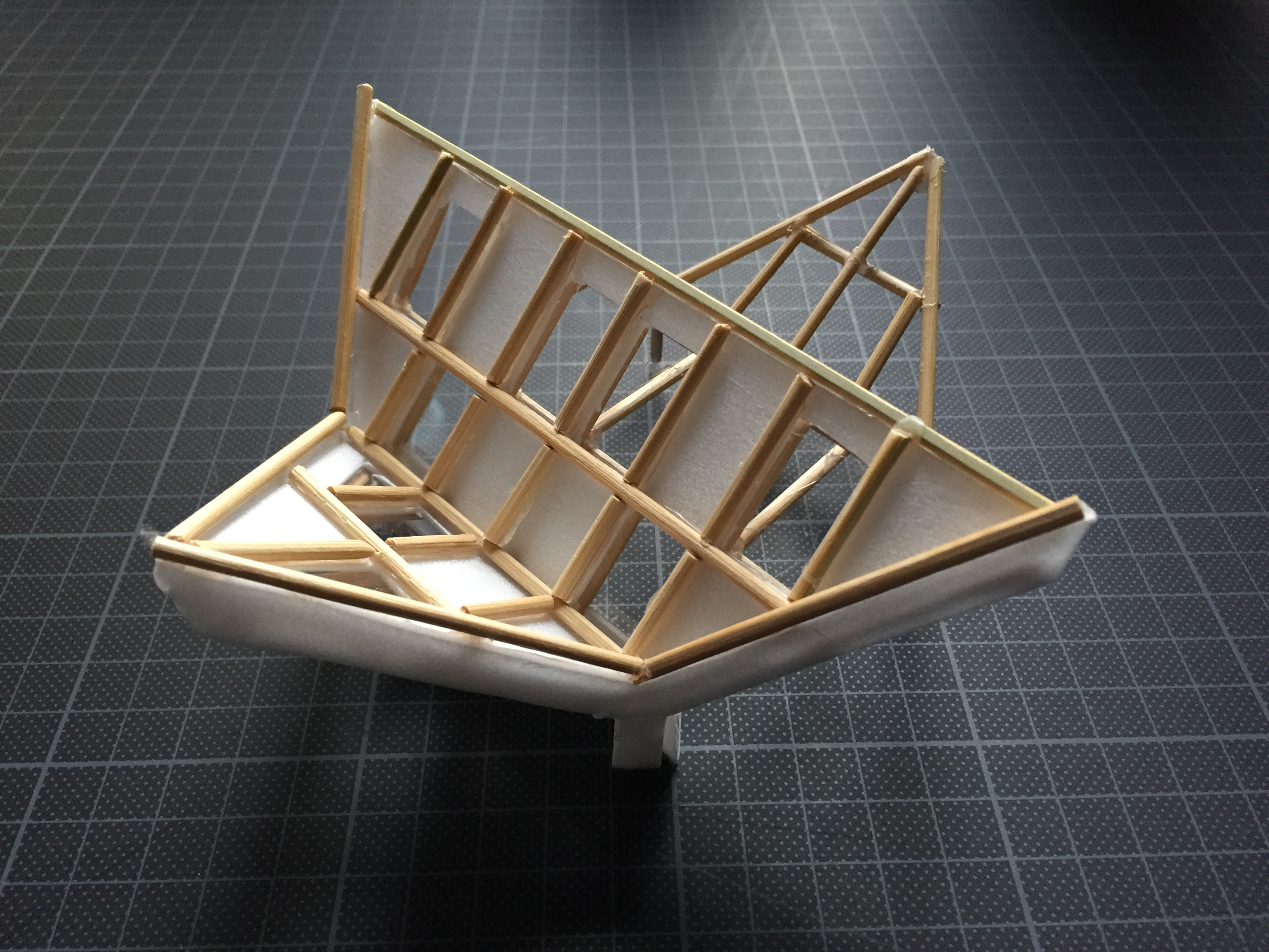
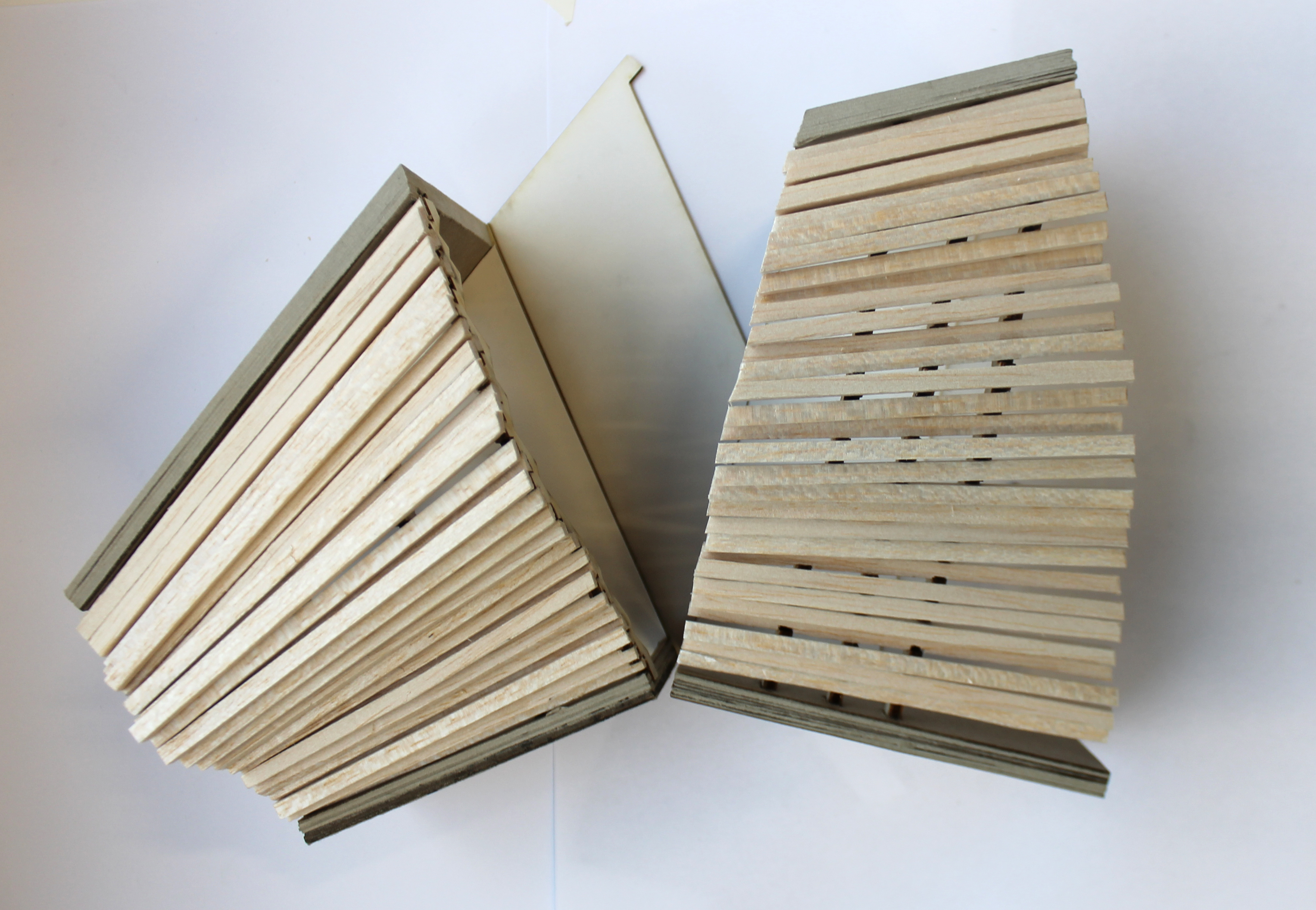
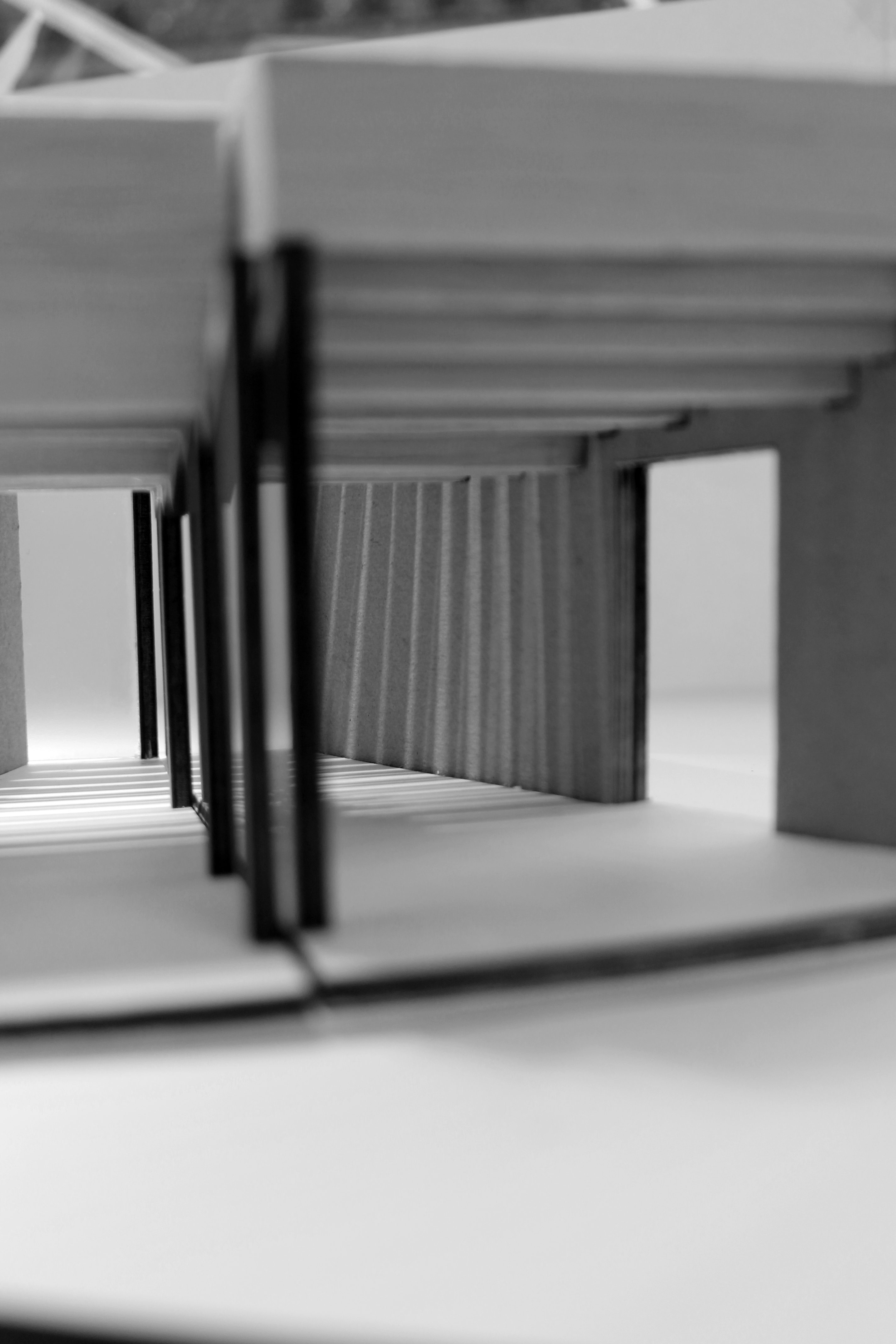
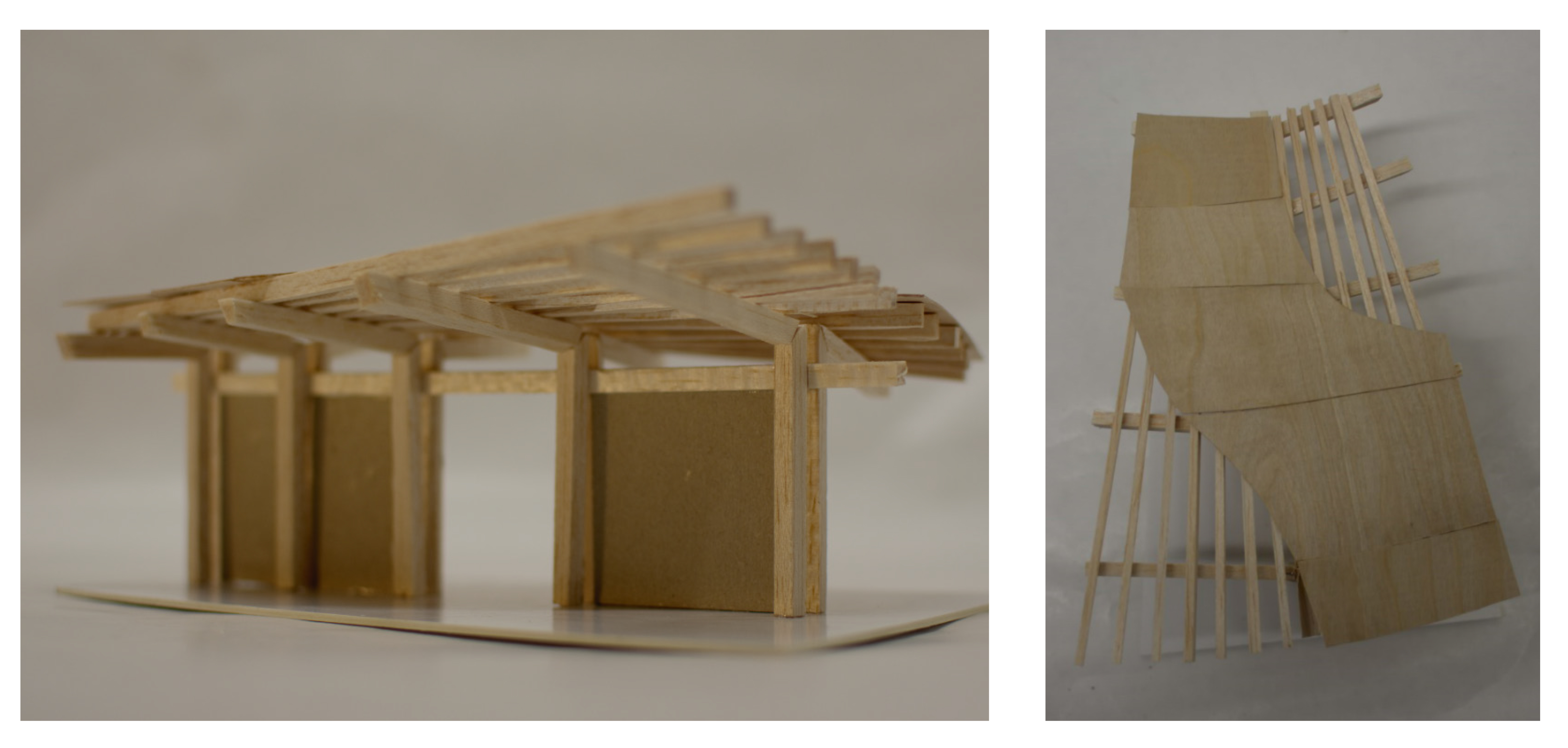
Development model – reviewing wall to roof connections

9

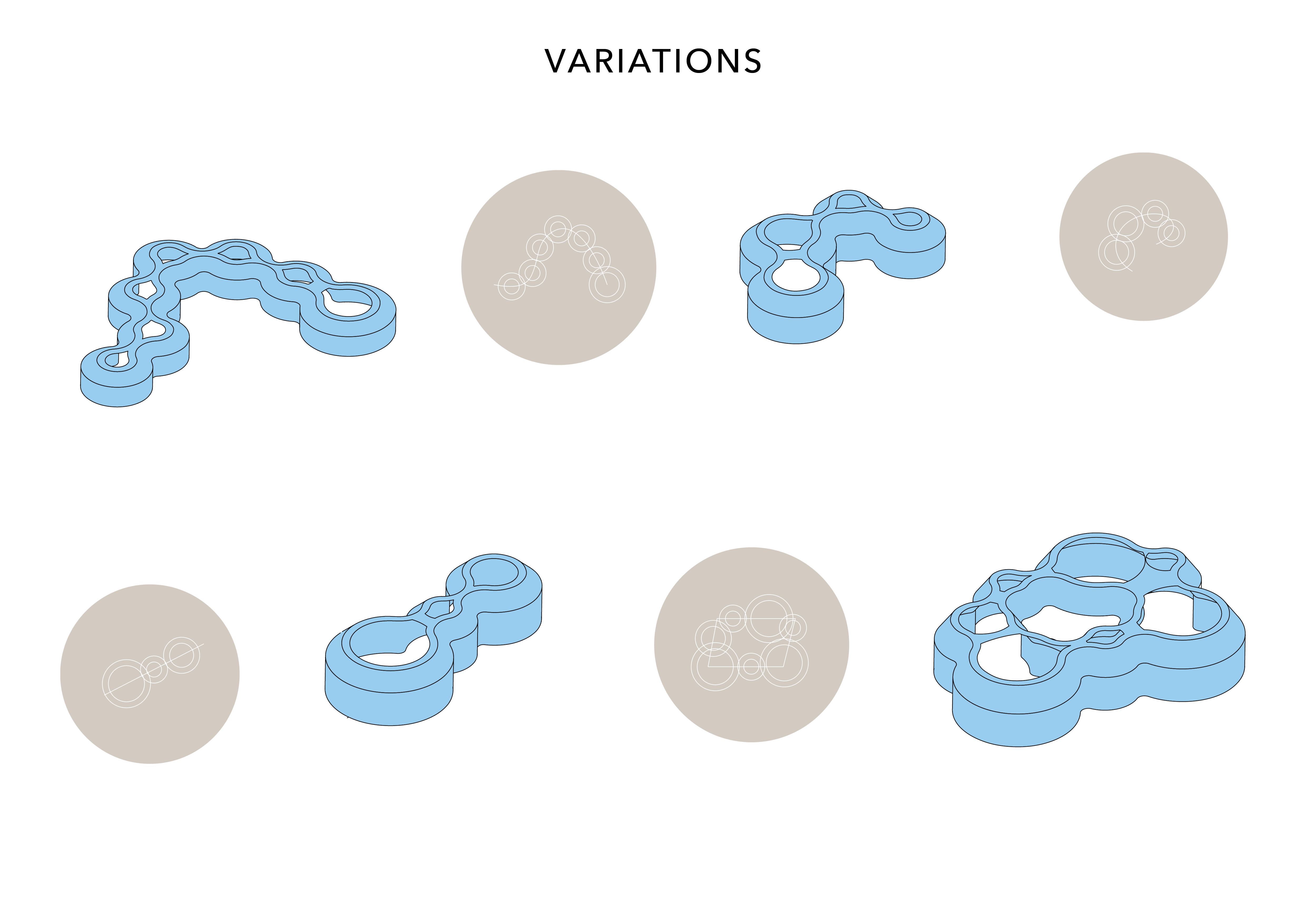
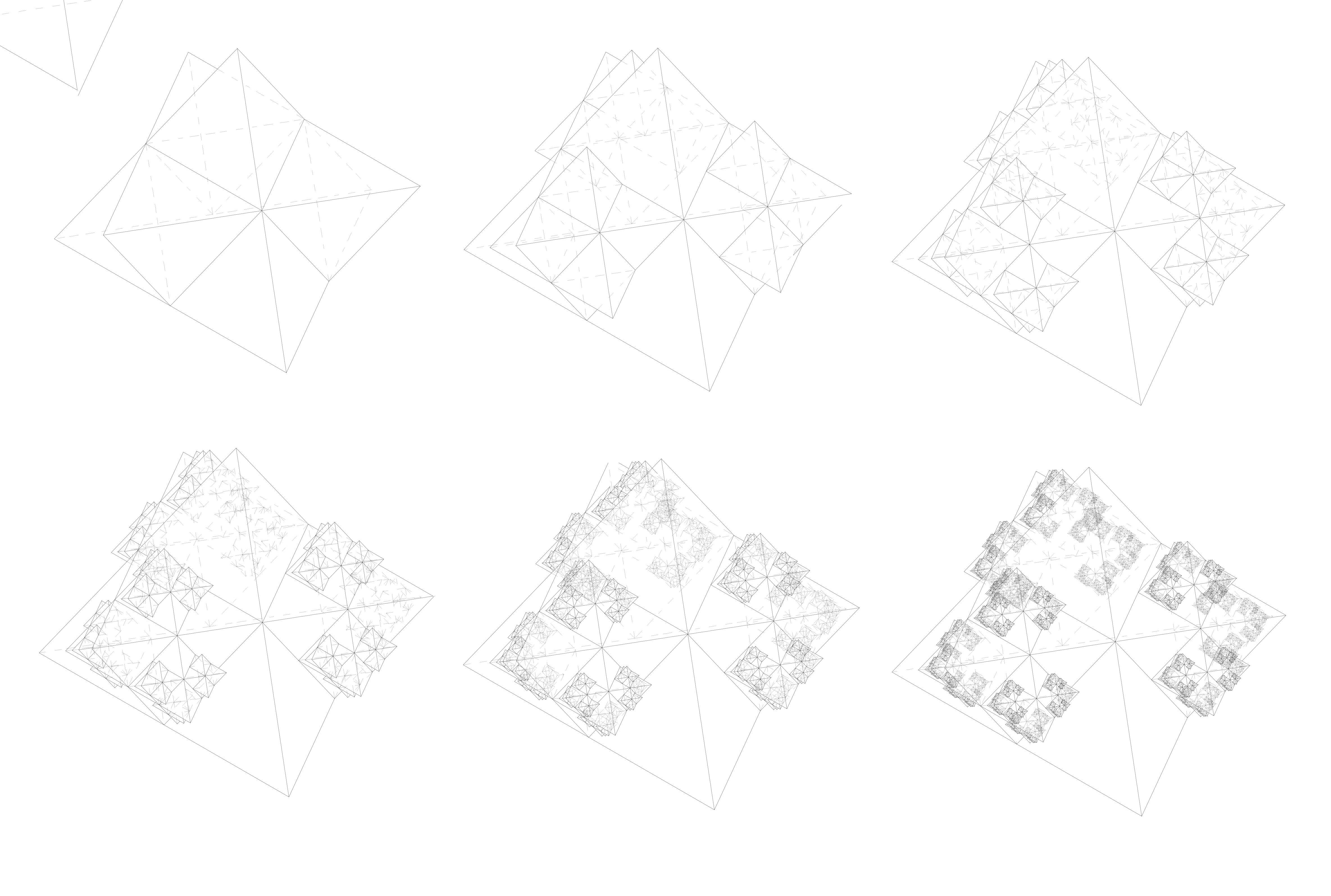
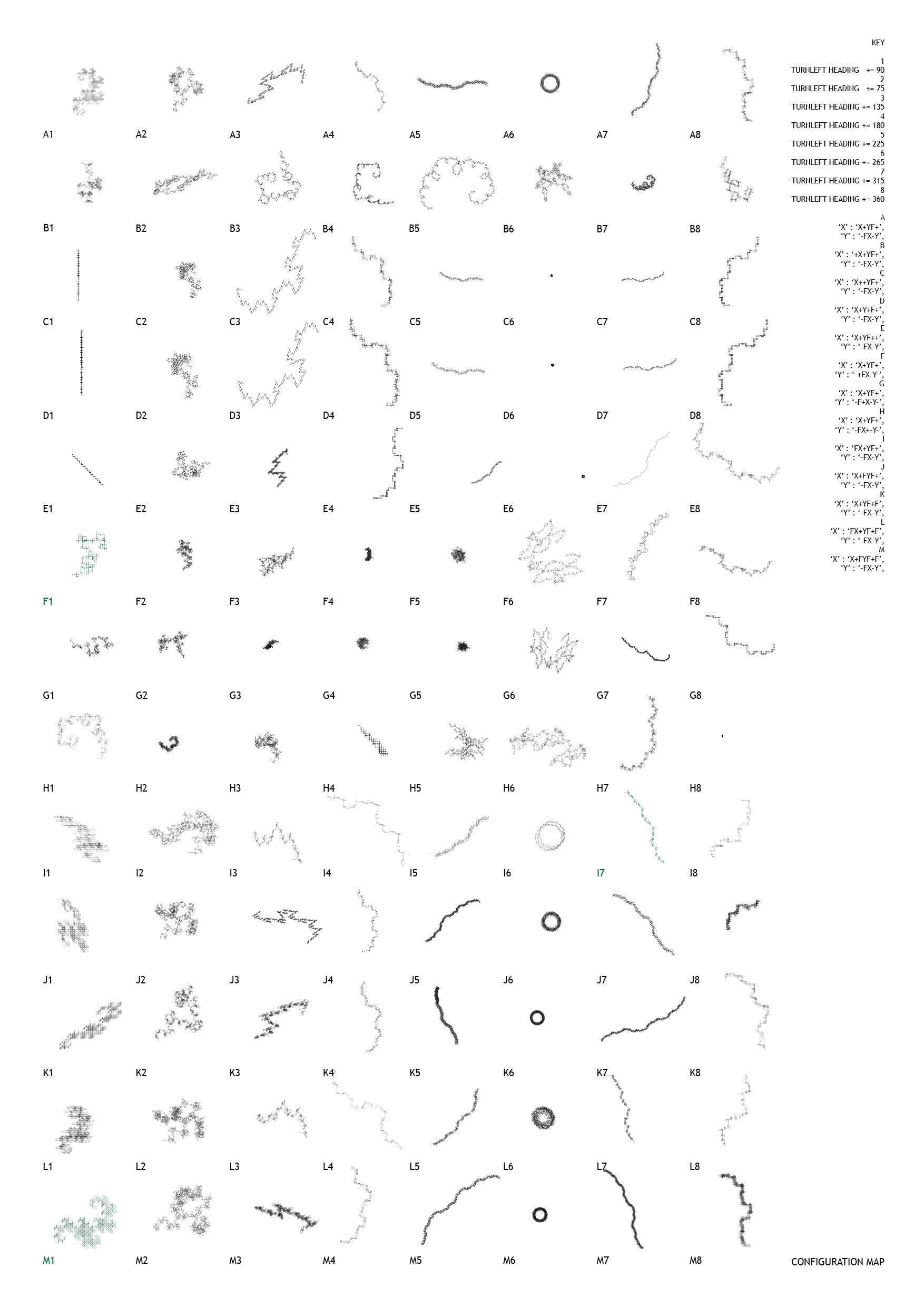
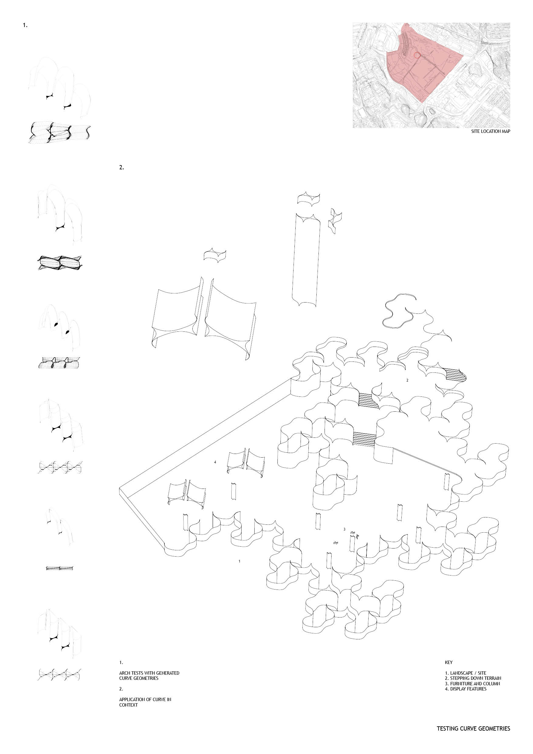
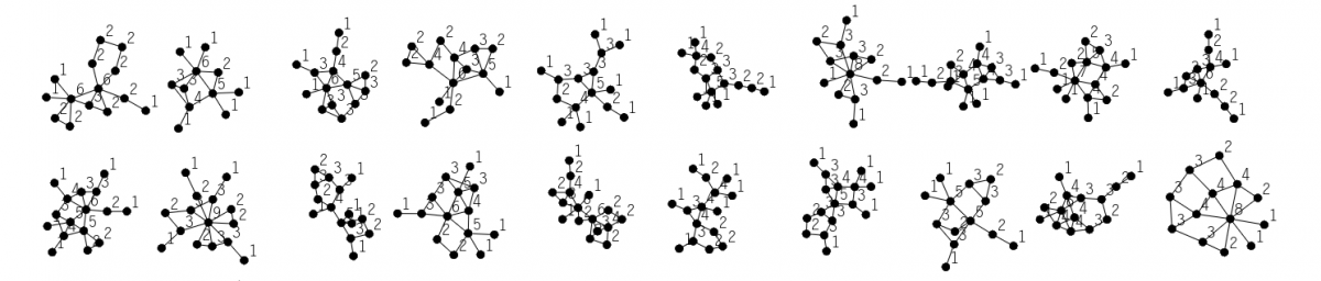
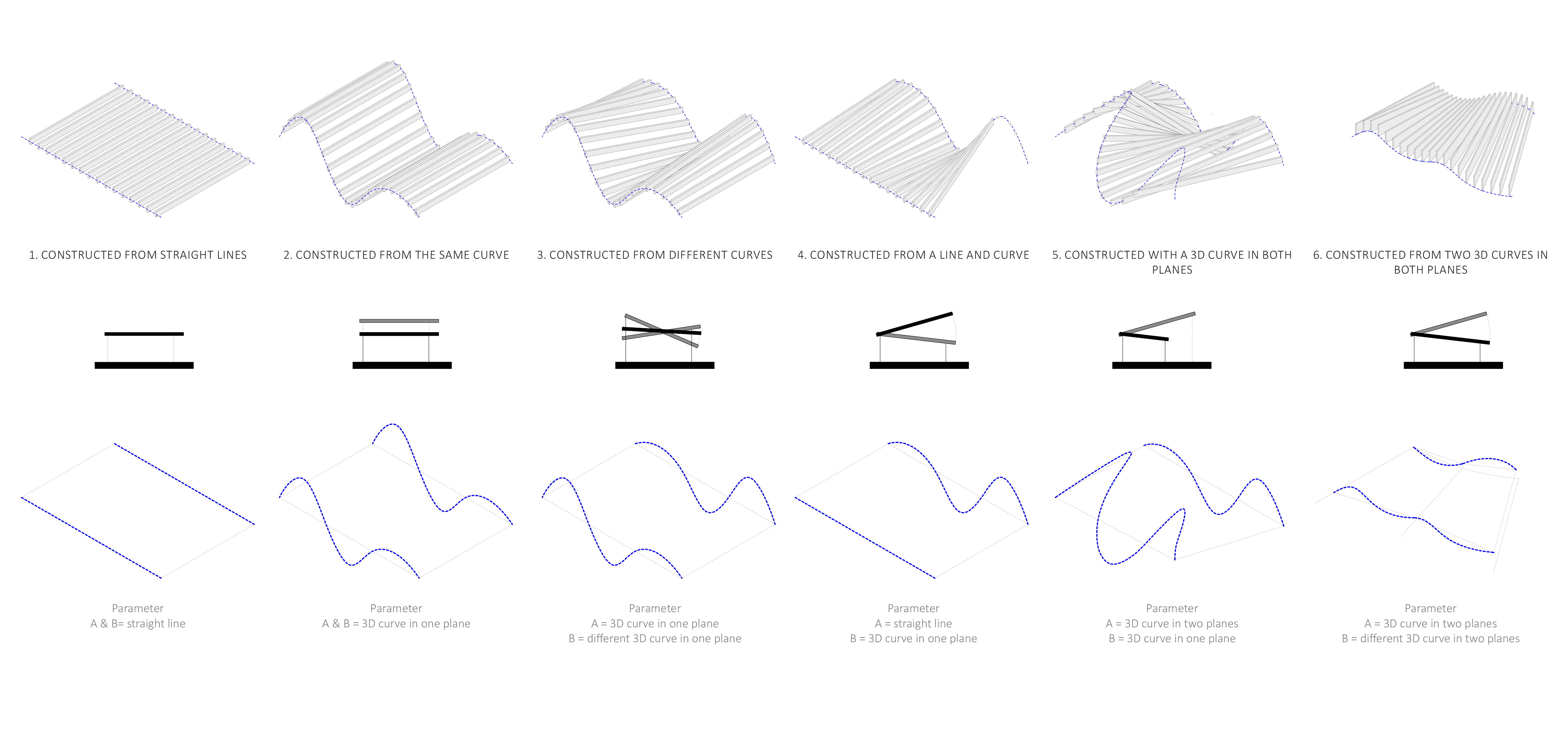
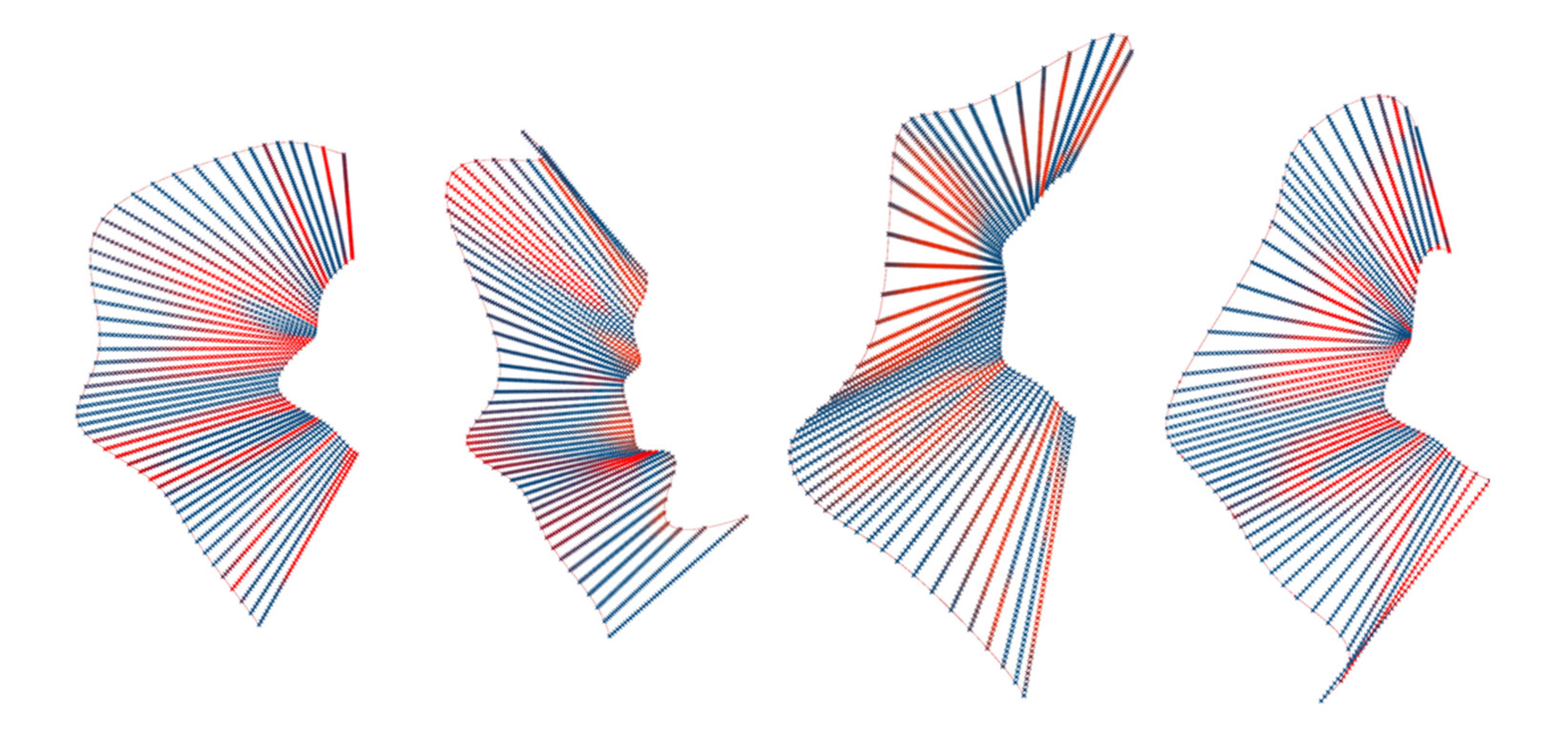
Analysing different input curves and the generations

6


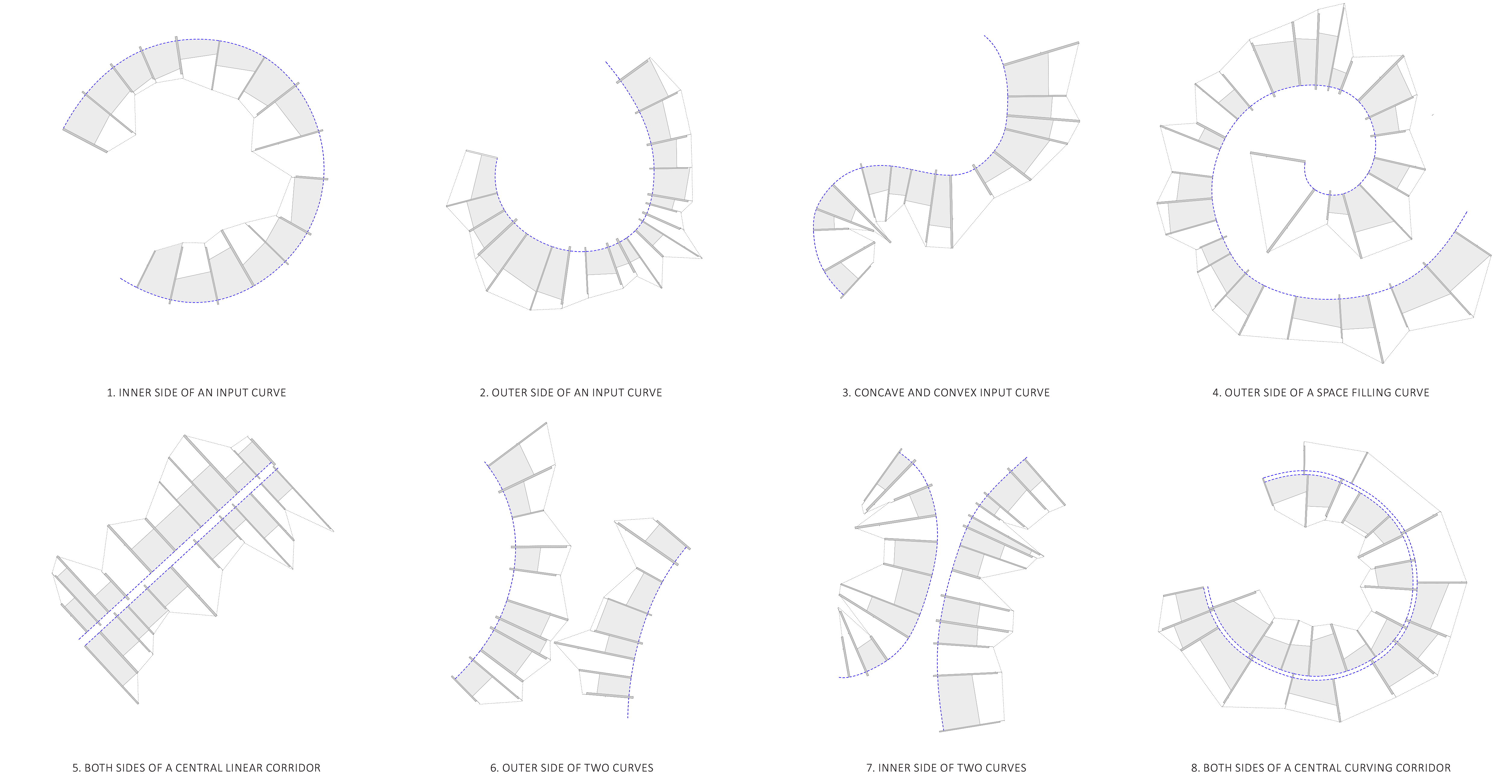
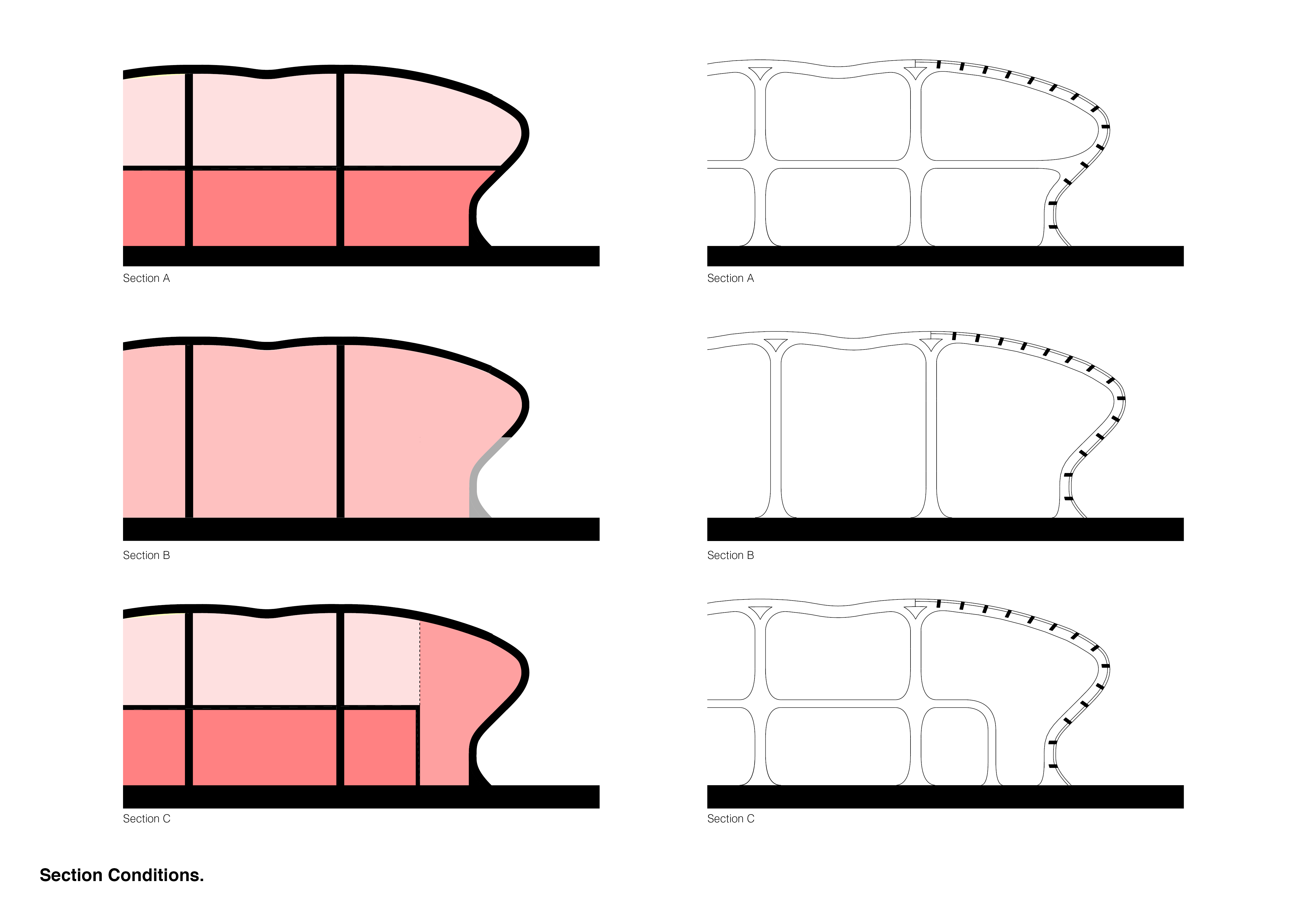
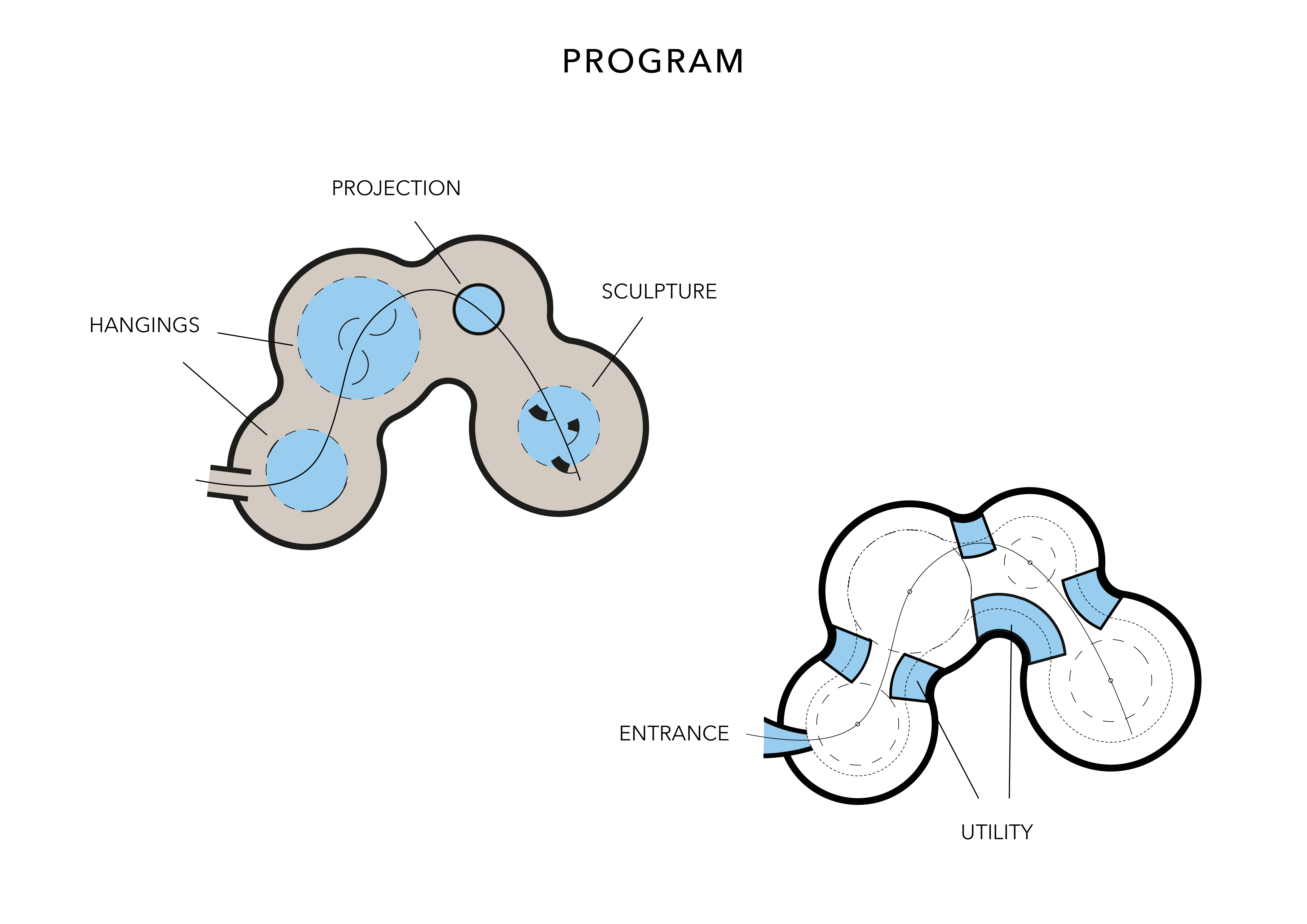
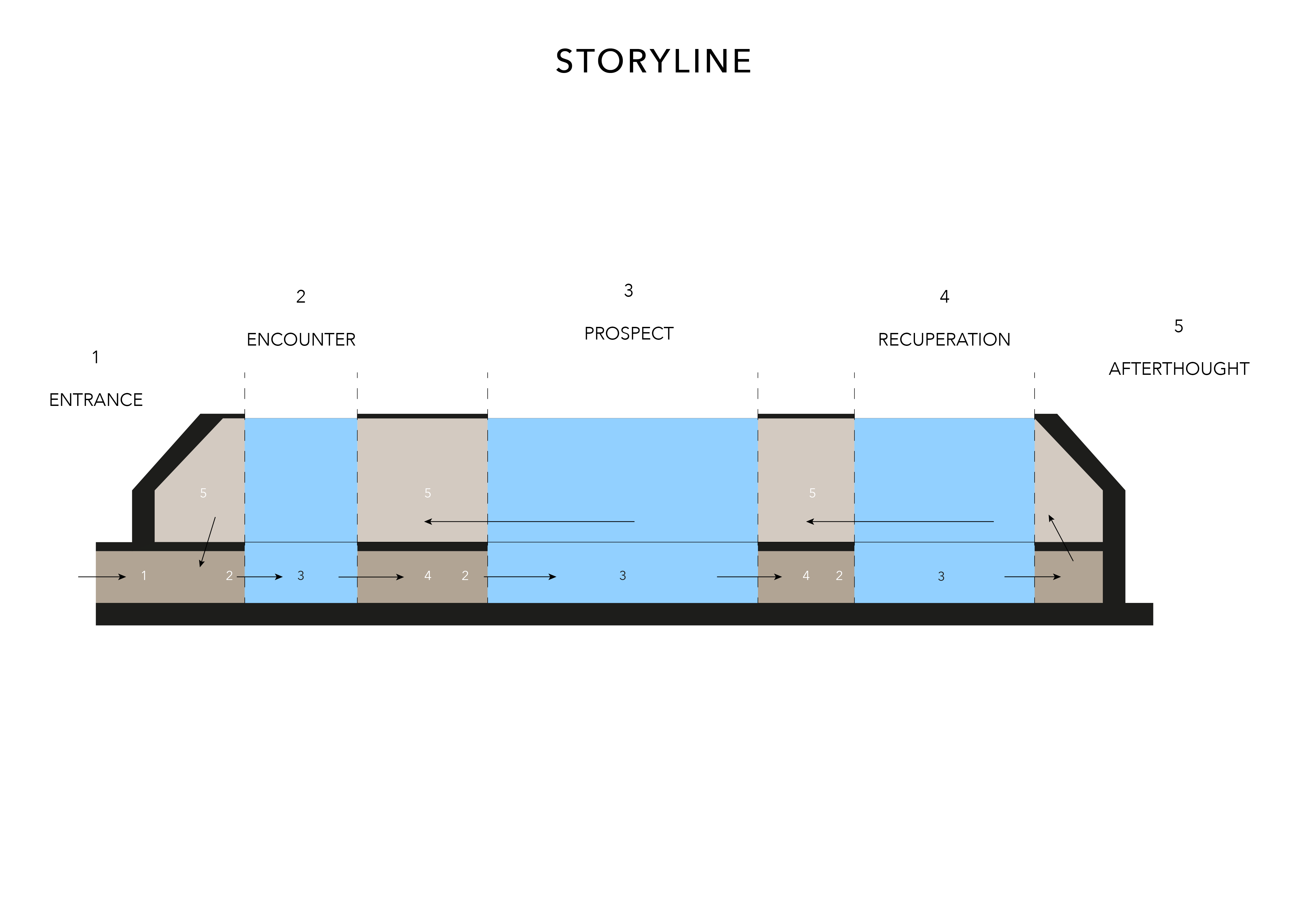
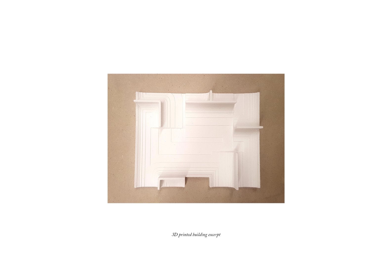
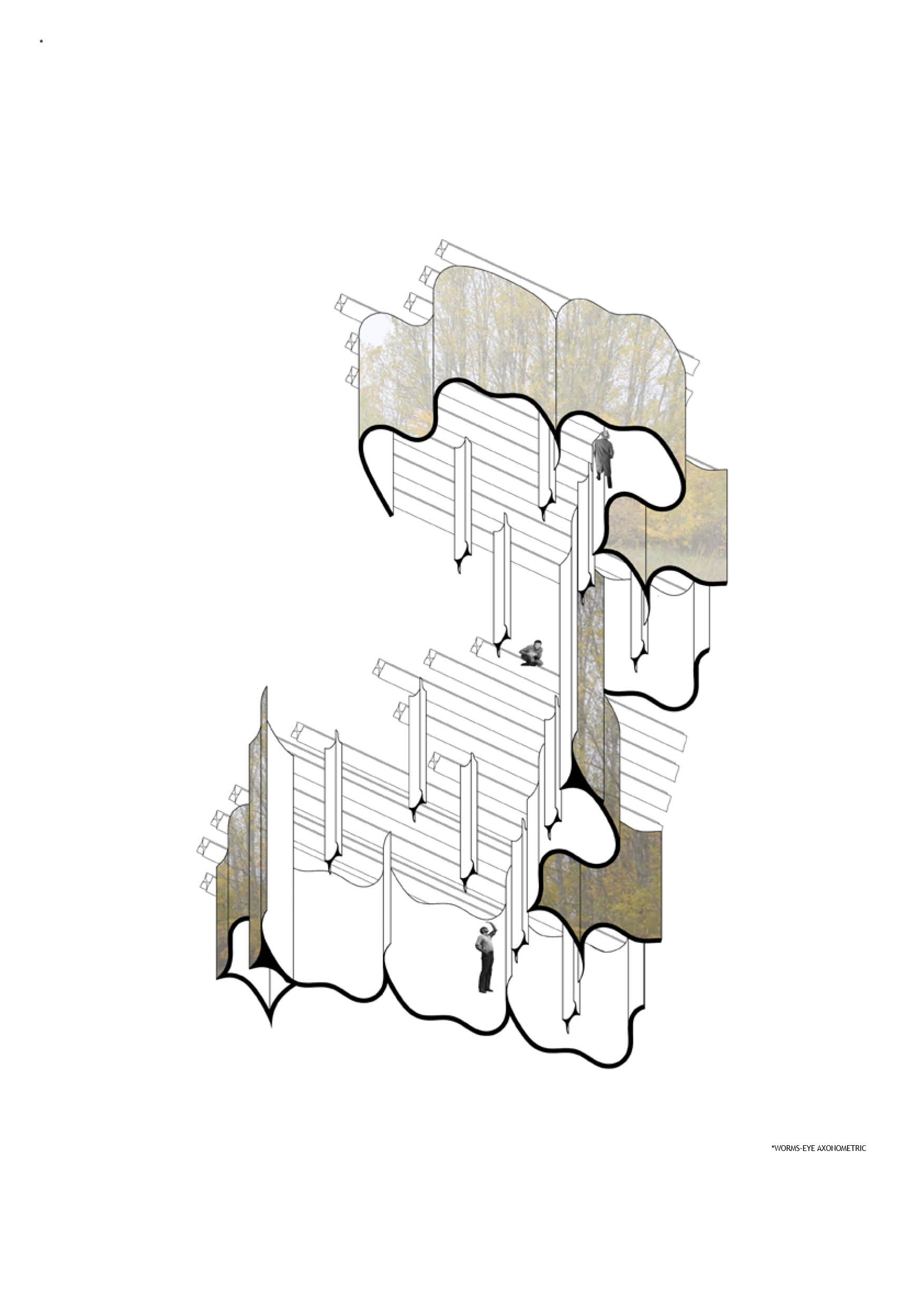
Classifying the spaces created

10


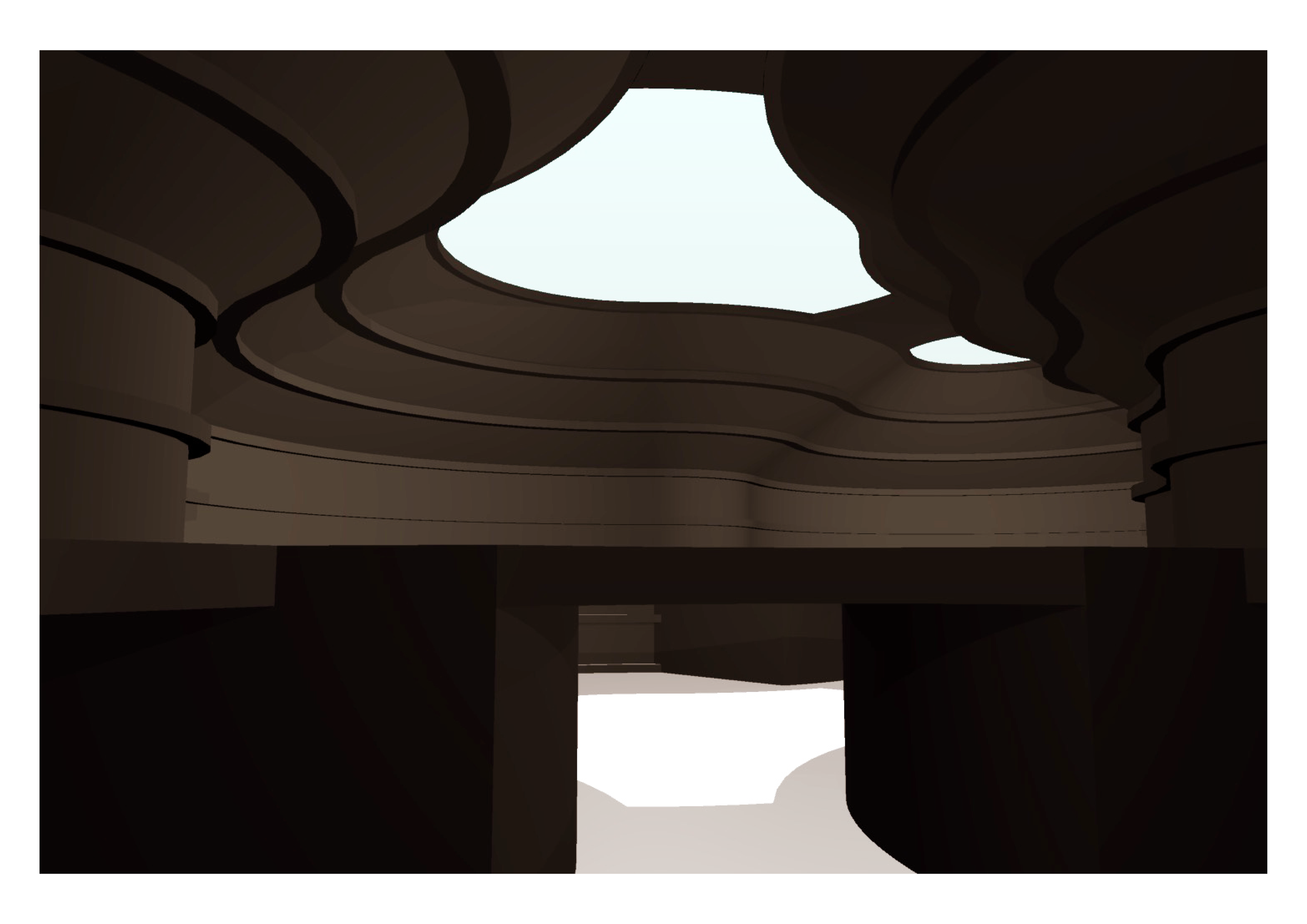
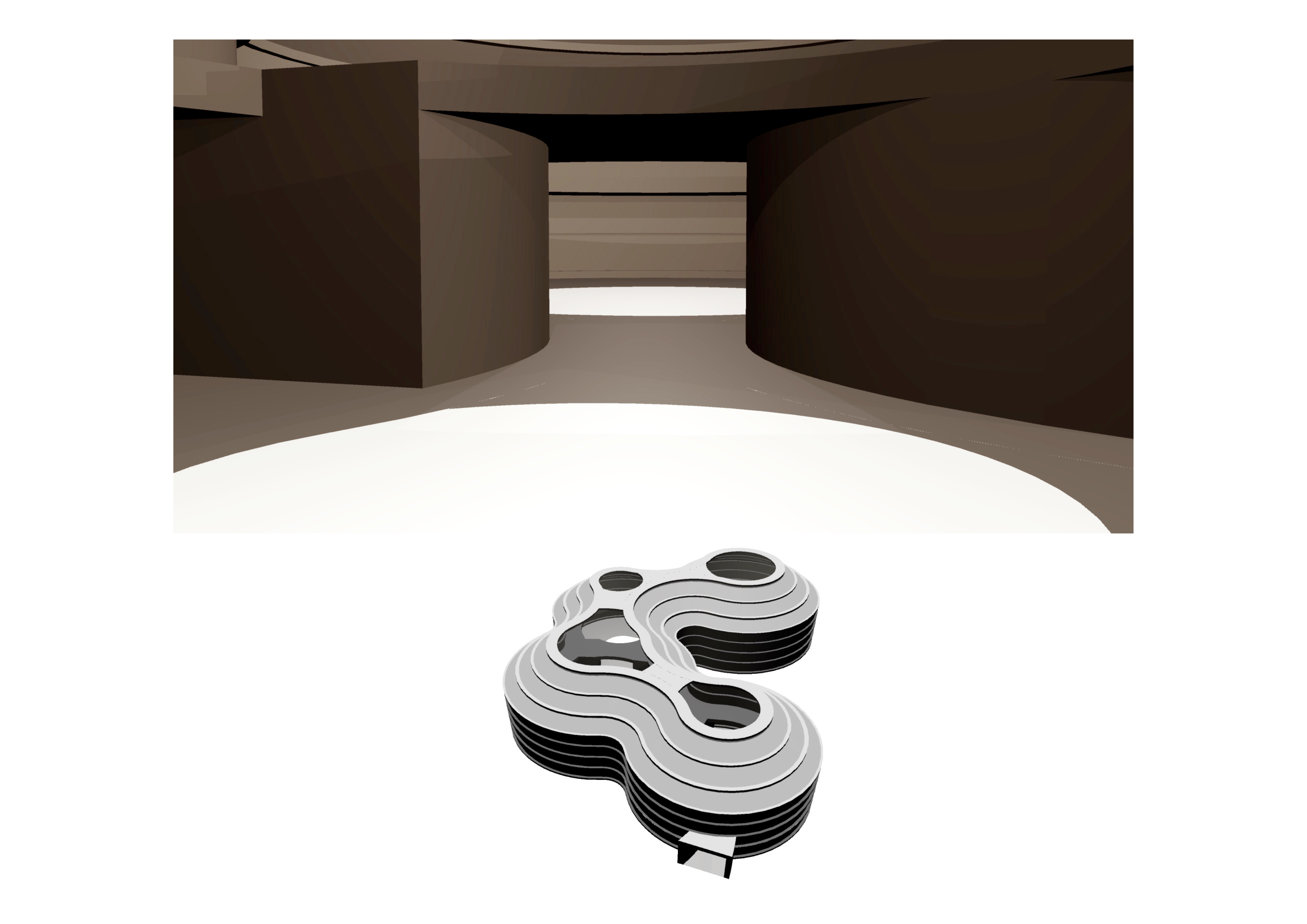
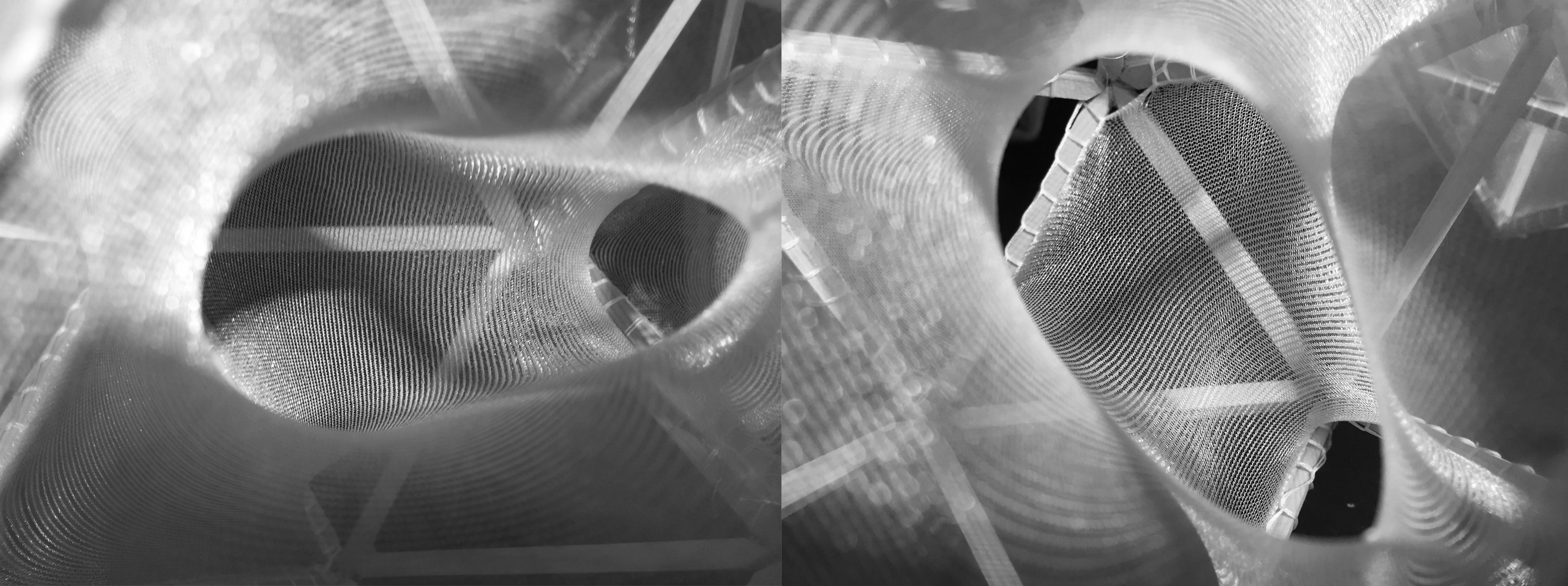
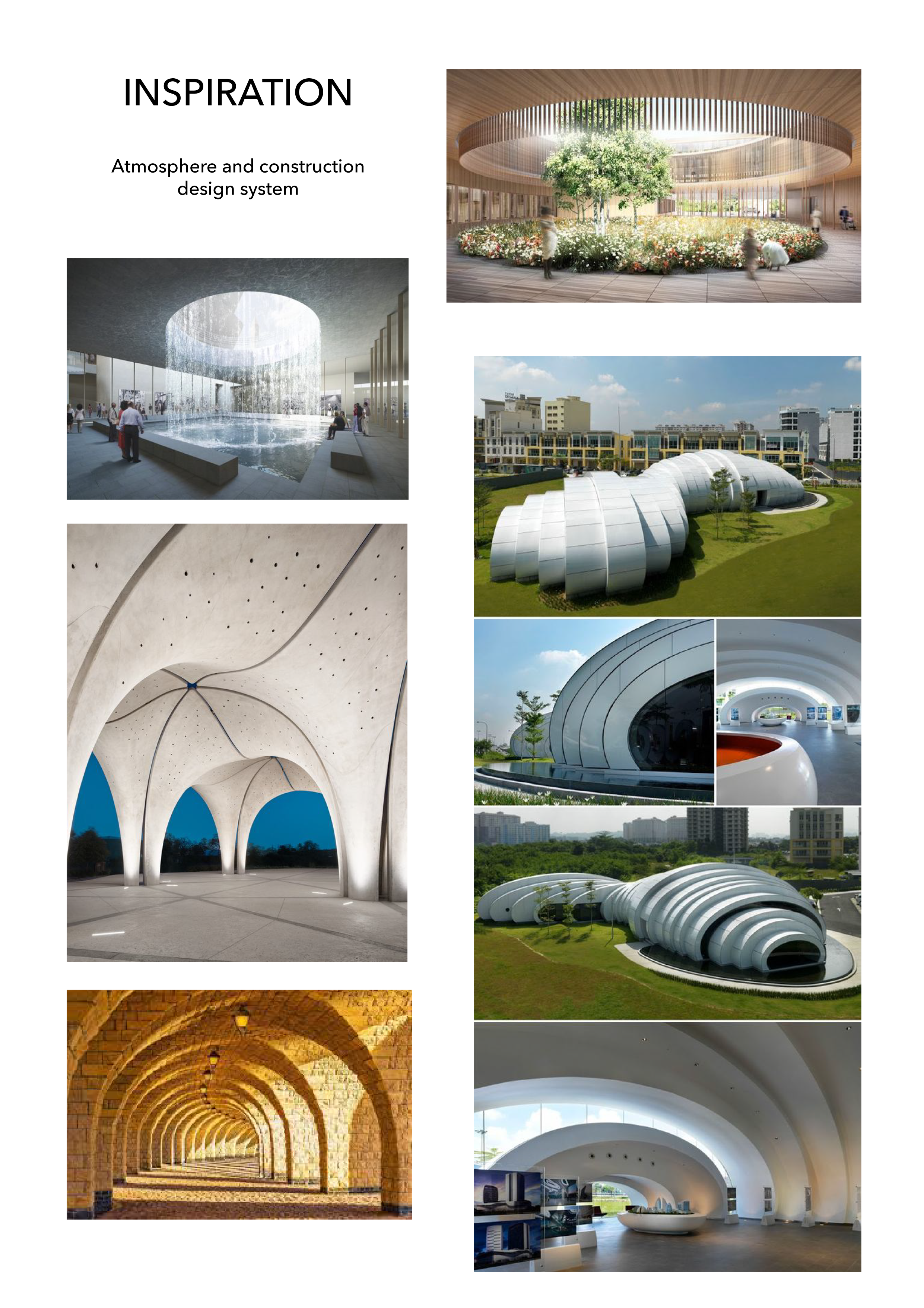
Implementing forced perspective into the structure


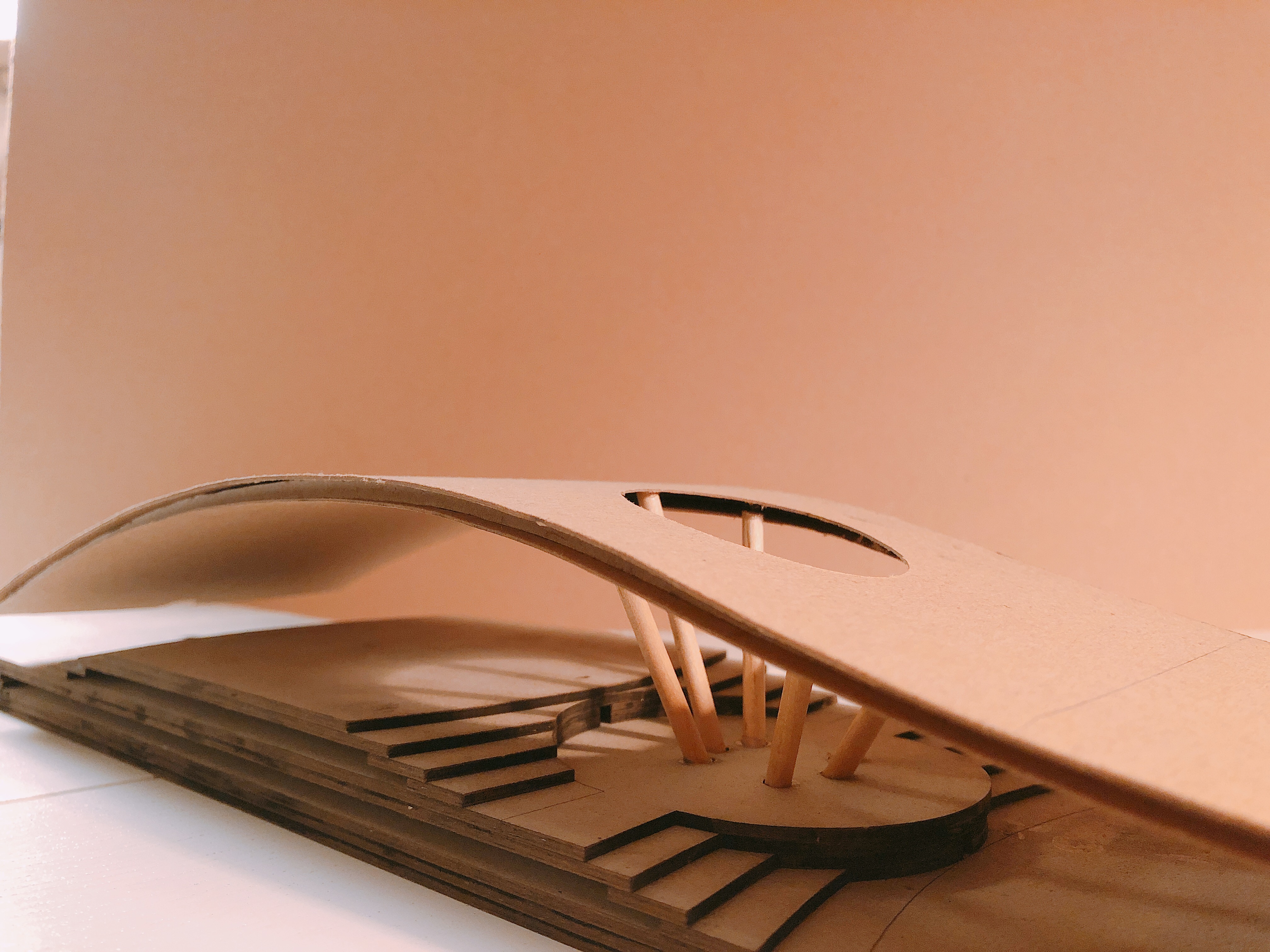
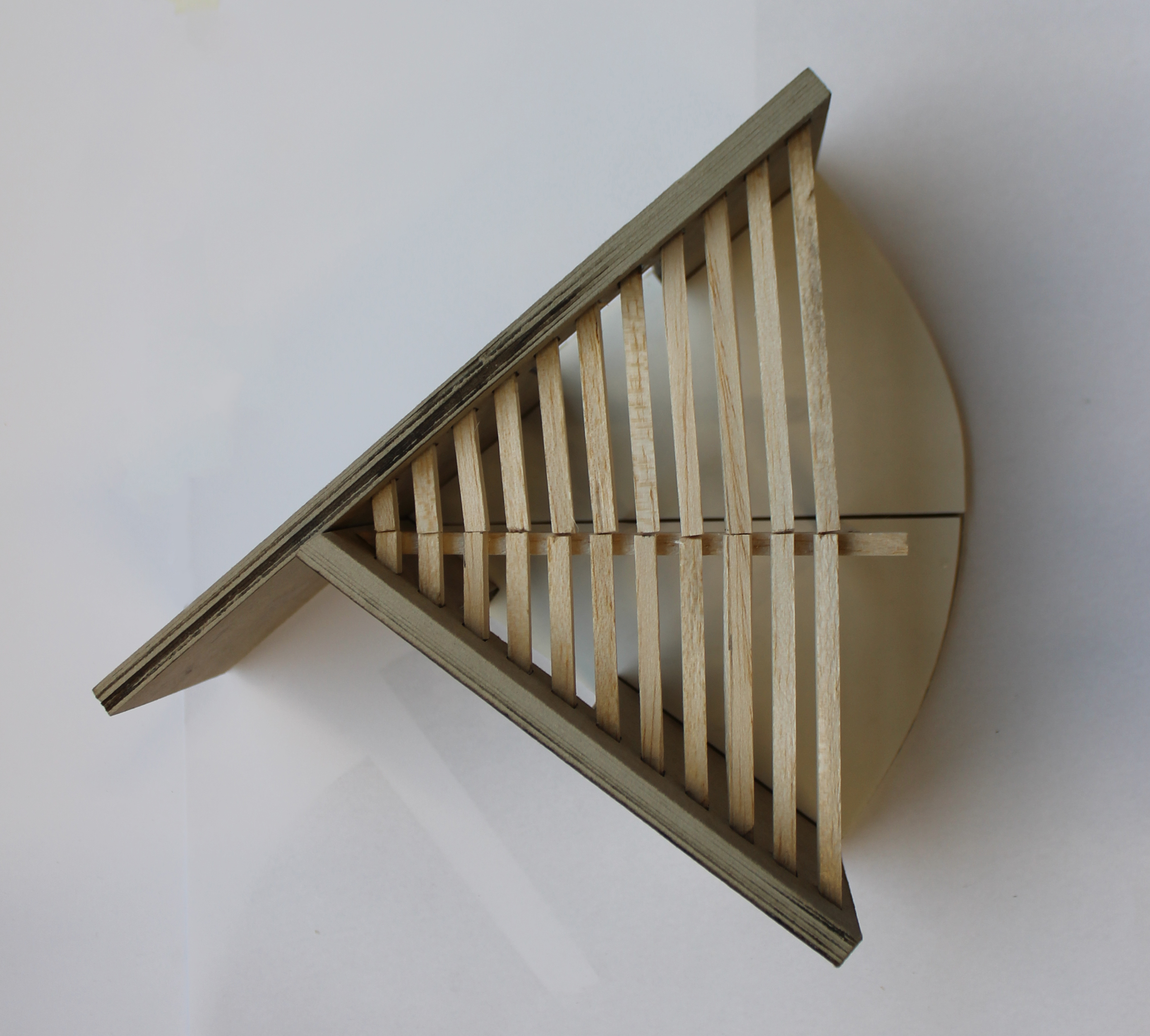
Development model – Full circle – roof begins to inform the plan

14

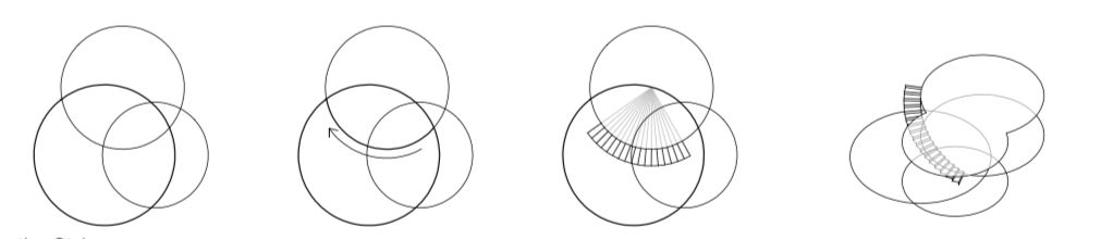
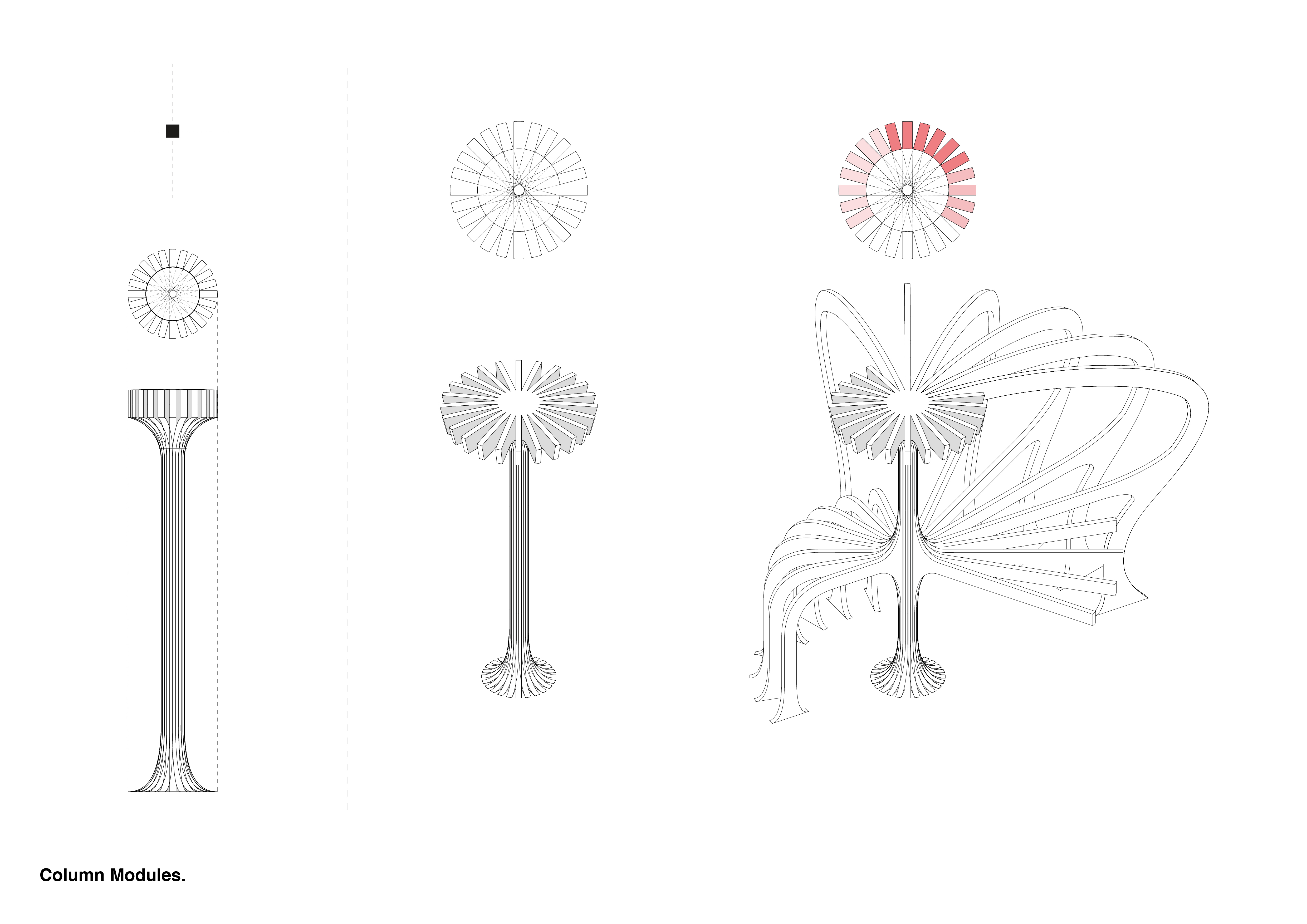
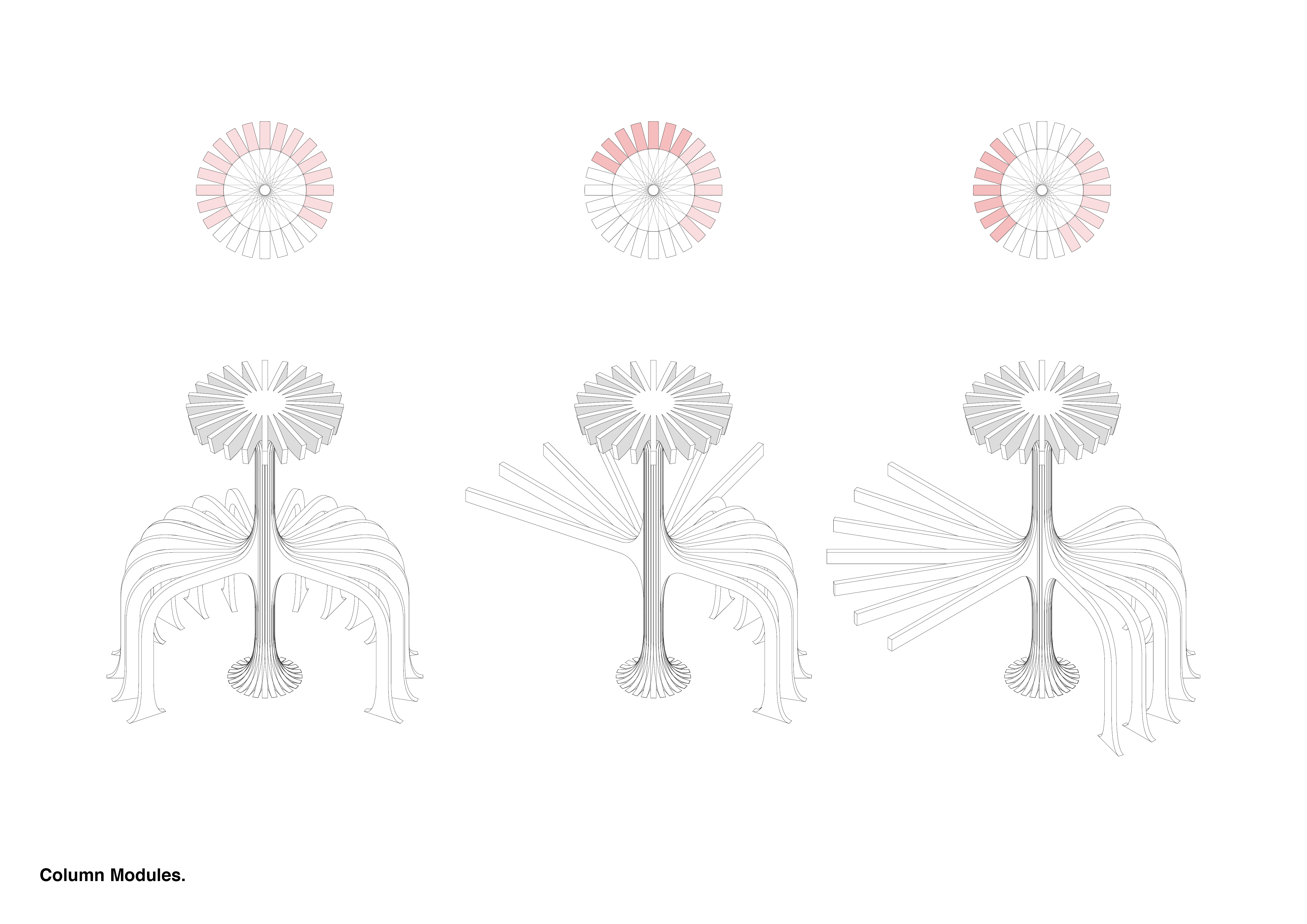
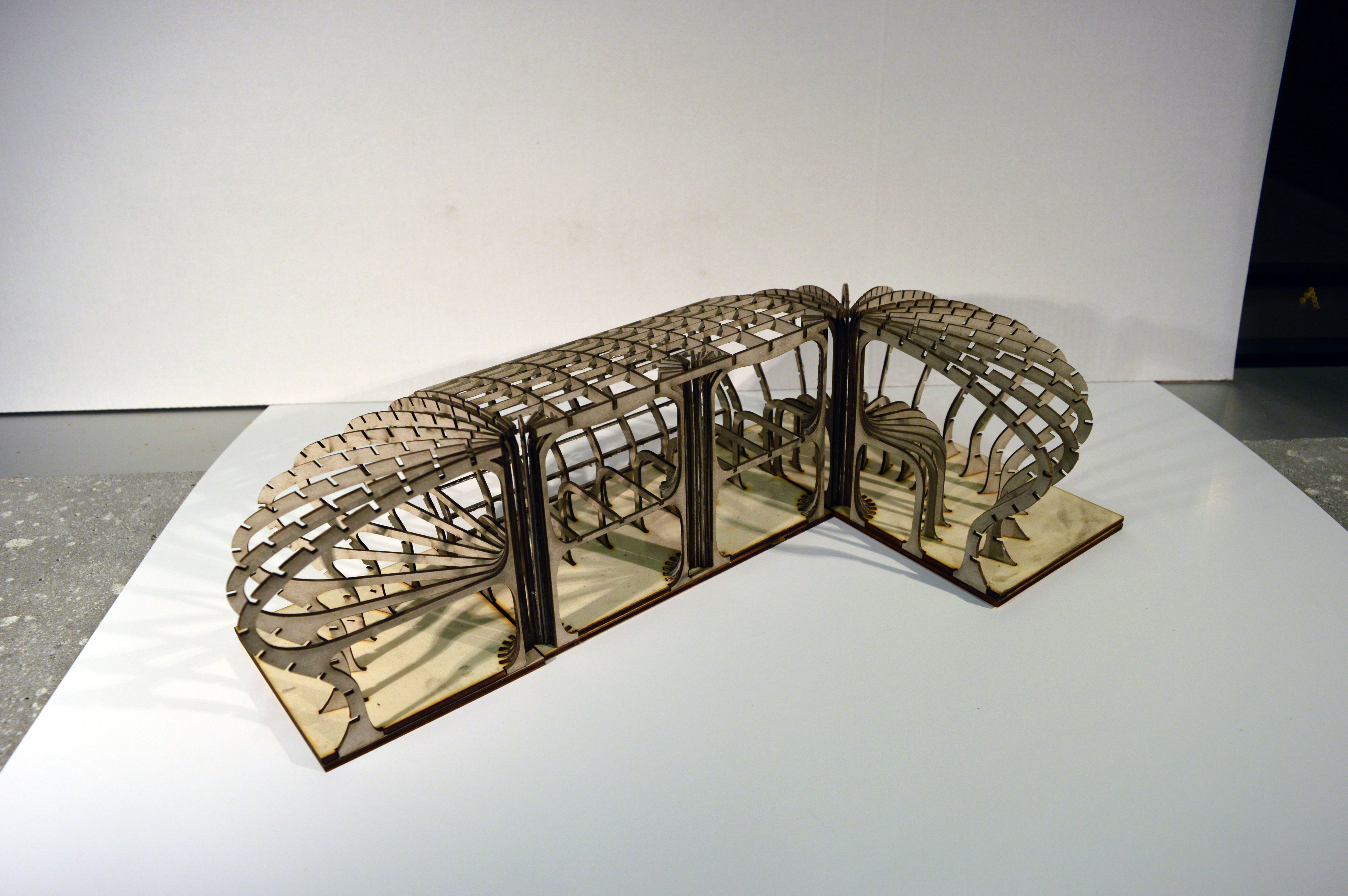
Radial structure – rationalising geometry and simplifying connections

15

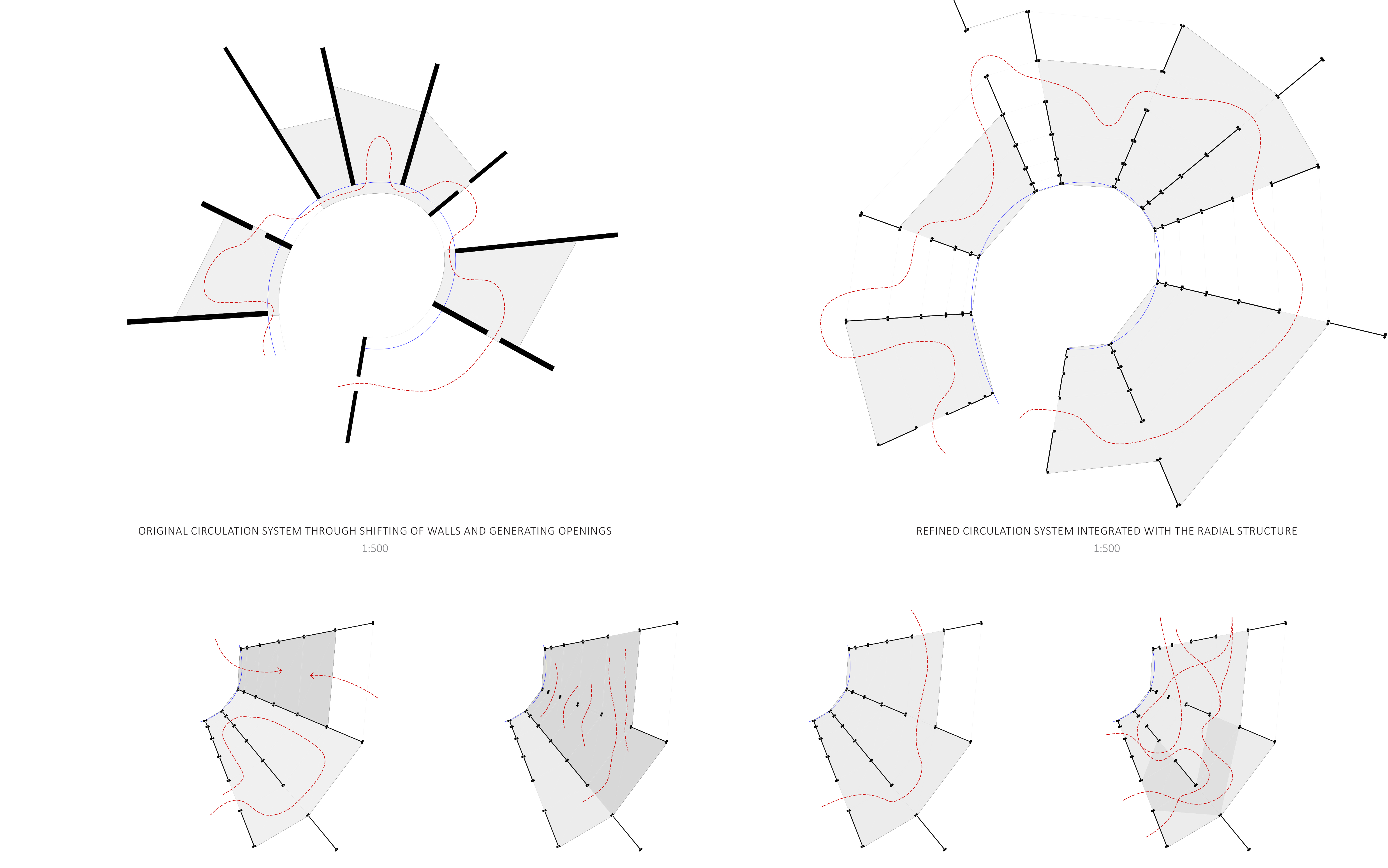
Radial structure – integrating the flexible circulation system

20.jpg


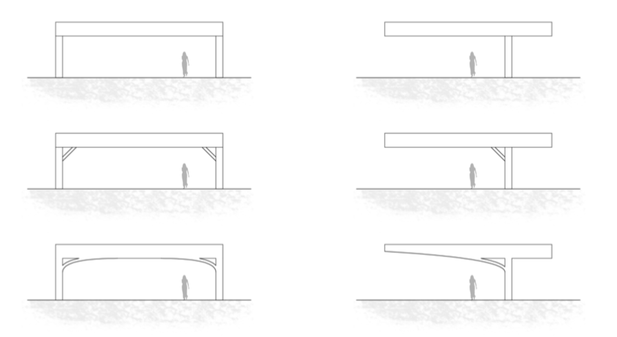
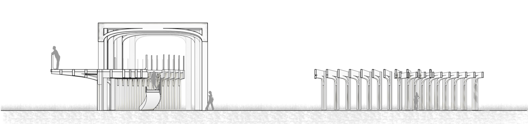
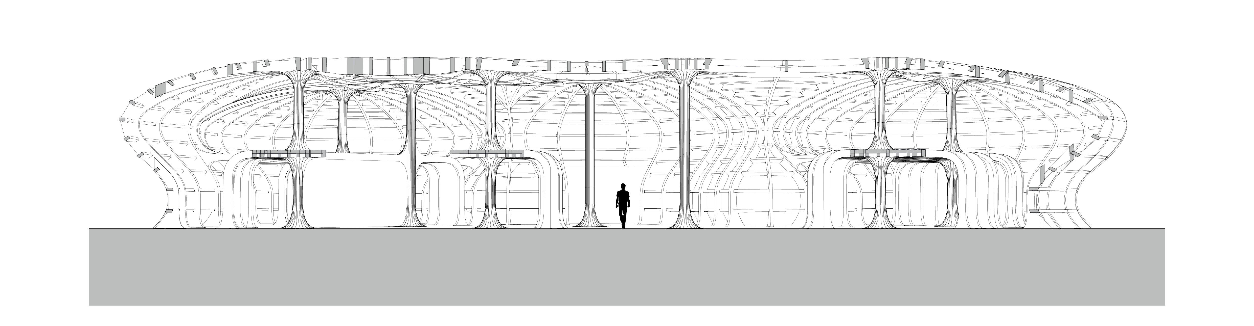
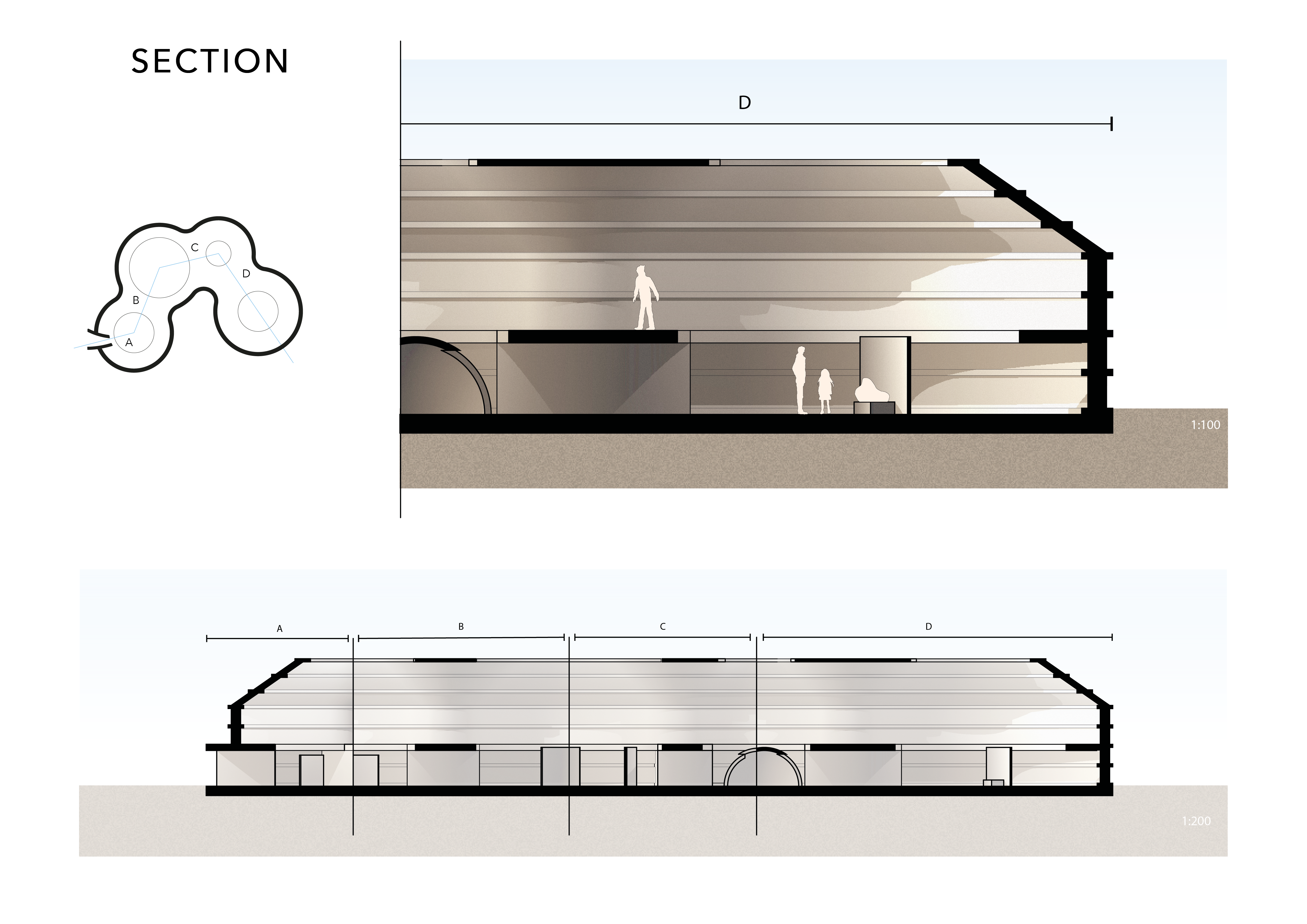
Roof curvature – Two curves vs one – how this affects the section through spaces

16

Analysing the gradient of the roof – walkable vs non-walkable 

18

Full integrated python and grasshopper system

19


Vennation

Screen Shot 2018-12-17 at 14.25.40
Edge Conditions
Screen Shot 2018-12-17 at 14.26.56
Frame Spacing
Screen Shot 2018-12-17 at 14.27.17
Column Placement
Screen Shot 2018-12-17 at 14.27.35
Indoor/Outdoor Options
Screen Shot 2018-12-17 at 14.27.46
Frame Geometries
Screen Shot 2018-12-17 at 14.27.55
Generating Stairs
Screen Shot 2018-12-17 at 14.28.06
Timber Joint Studies


Screen Shot 2018-12-17 at 14.31.09
Process – Inputs
Screen Shot 2018-12-17 at 14.53.35
Plan
181212_exploded axo 100
Exploded Isometric
Screen Shot 2018-12-17 at 14.35.49
Perspective Section
Screen Shot 2018-12-17 at 14.36.01
Elevation
Screen Shot 2018-12-17 at 14.36.25
Model – 3 Indoor Spaces
Screen Shot 2018-12-17 at 14.36.46
Model – Support Geometry Tests
Screen Shot 2018-12-17 at 14.37.30
Model – 2 Indoor and 1 Outdoor Spaces

Continuous columns.

Glasspool_Jack_Project02_FinalBoards

To develop my original generated Python plan into a 3D structure, I began by analysing sectional and spatial conditions. Dividing the plan into three key sections I identified the key spaces. The structure of the section followed the original generated curve which remained consistent throughout the building. The big difference occurred internally when the interior sections interacted with the outer frame. I looked at the key intersections and adapted these in section so the language internally was consistent with the external.

Glasspool_Jack_Project02_FinalBoards2

Looking at these sectional pieces further I listed out all the varying arrangements of the sections to develop a list of modules which when orientated according to the generated plan could begin to form the undulating structure of the building.Glasspool_Jack_Project02_FinalBoards3

DSC_0609


When modelling the structure I found the column intersection could be used as a basepoint to generate both the interior and the exterior framework for the gallery. By referring back to my original grid, each section of the building was dictated by the number of columns in a corner of a square. With this information I was able to split the building into 5 modules which could be repeated and orientated in the grid to form any building configuration generated by the code.

Glasspool_Jack_Project02_FinalBoards4Glasspool_Jack_Project02_FinalBoards7Glasspool_Jack_Project02_FinalBoards8

Using the 3 types of sectional modules listed previously, the individual columns could be adapted on a secondary level. With the new structural modules remaining consistent, the interior spaces can be generated by varying the type of supports that span form the columns, using different modular sections to suit separate spaces. This system can be used to combine the exterior, interior, and structure of the generated building.

Glasspool_Jack_Project02_FinalBoards5

Glasspool_Jack_Project02_FinalBoards6

Undulating roof & column intersections:

DSC_0438

Combining these systems together I was able to create an example structure for housing the art gallery:

Glasspool_Jack_Project02_FinalBoards92Glasspool_Jack_Project02_FinalBoards9


From system to form

The last part of the project has been about developing the structure. Since the system in itself only generates a very basic diagram, the possibilities for translating it into architecture seems endless, but at the same time I wanted to stay true to the underlying system. The first idea of using domes was too diagrammatic and a constraining system.

Instead, the offset circles are joined and filleted to form the general shape of the exterior walls. That shape then lays the groundwork for the shell structure, extruding it vertical to shape walls and offsetting them inwards to create a sloped roof, naturally shaping openings around the Glades beneath. The structure consists of a primary, vertical structure, and bands of secondary outlines, visible both externally and internally.

S9 P2 FINALS_pics5

S9 P2 FINALS_pics12

This project has forced me to analyze my own design process, and pushed me outside my comfort zone. It has also been an interesting struggle between me and the system, by being so smitten with the possibilities of the tools we have investigated, and then realizing that I need to take back the power and tame my own system. Writing a Python program from scratch defined this project because of all the possibilities it created, and the challenge to extinguish a simple form to be translated into architecture.


S9 P2 FINALS_picsS9 P2 FINALS_pics2S9 P2 FINALS_pics3S9 P2 FINALS_pics4S9 P2 FINALS_pics6S9 P2 FINALS_pics7S9 P2 FINALS_pics8S9 P2 FINALS_pics9S9 P2 FINALS_pics10S9 P2 FINALS_pics11S9 P2 FINALS_pics13S9 P2 FINALS_pics14

Stereotomy between two curve variations

After reaching a set shape and logic of spatiality, the goal was to work this relationship between floor and ceiling with architectural accuracy and detail. The different levels had to be closely linked but entirely different when it came to their ambience and purpose. Another interesting development was the solving of the structure, metal rings linked by beams which sit like a Victorian dress on four walls and ten columns (six of them at the center of the project).

Everything was rescaled and redesigned to have greater comfort when walking, better options when pausing and resting, and to maximize the space possibly used for infrastructures and additional controlled exhibition areas.

Curves not angles.

Drawing from the research and testing throughout project_01 and _02, I began to compile and implement the system I created in order to give architectural form to the space filling curve that is the dragon curve. The path and control points of the test M1 from project one inform the grid along which both the walls and roof structure are set, thereby enforcing a direct correlation between section and plan. Altering parameters such as thickness, scale and spacing of the walls and roof, with respect to desired lighting, movement, material etc. can easily be navigated as the structure and form are resolved thanks to the connection in plan and section

.

Reflections on structure

While looking at inspiration for dome structures and sequential buildings, it became clearer that the system and the theme and atmosphere it creates is more important than the structural system of the building. In other words, the perfect or nearly perfect dome as an encapsulating system is questioned. Instead, points of interest, both from a structural and thematical point of view, is identified. These could be used as a set starting point for finding a structure that will enhance both the Glades and the system itself.

St9_P2_Task2_diagrams-02

Inspiration of atmosphere and structural alternatives other than “perfect” domes.St9_P2_Task2_diagrams-01

Radial roofscapes

After experimenting with a range of different input curves to see the different outcomes produced, I began to analyse the different types of spaces produced depending on the magnitude and type of curvature. From this I classified 5 different situations below, and started to visualise how the differing geometries affected the views within the spaces, the views out, and the conditions of the spaces.

curve tests.psd

From this I selected three of these conditions and started to explore the materiality and thickness of the spaces. I became interested in forced perspective and how I could apply this to the generated spaces to make shallow spaces feel deeper and vice versa. But also distort and effect the users experience of the space in different ways.

Panel.indd

Within the three sectional models below, I explored both in section and perspective. Looking in section at how the beams and and roof could connect and sit within the walls, but also how the spacing could change to play with forced perspective. Then the sectional models would be combined to allow myself to visualise the views within the spaces and the views out from them. I took a step back from the previous model where I was looking at a continuous roof system and looked at each of the 3 modules individually to look at different ways I could structure the roofscape and play with the lighting of the spaces.