Master thesis final submission

Compression-only based structures.
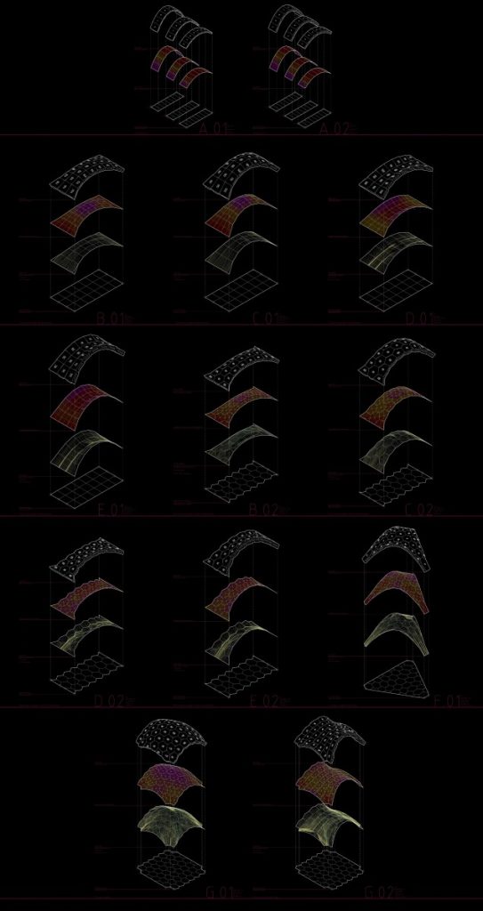
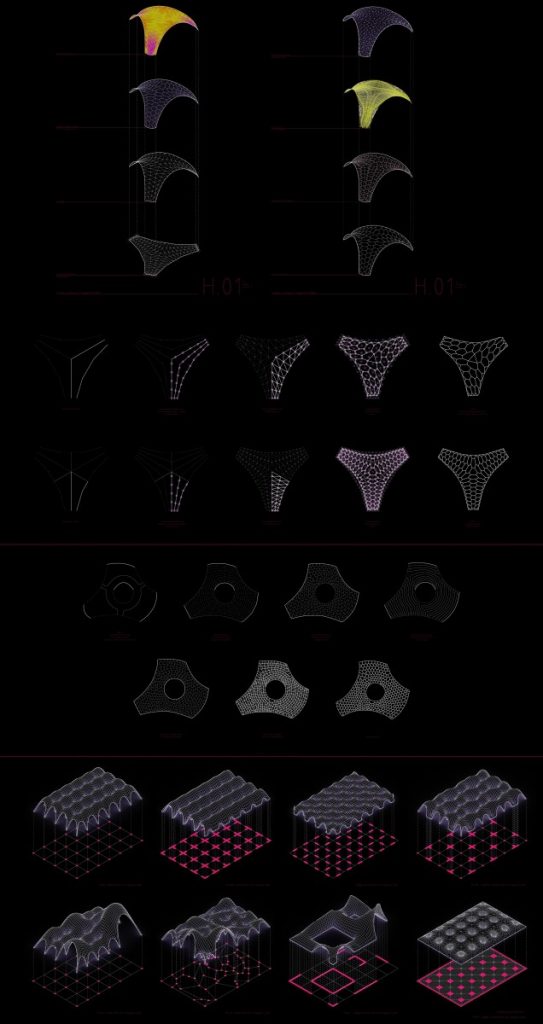
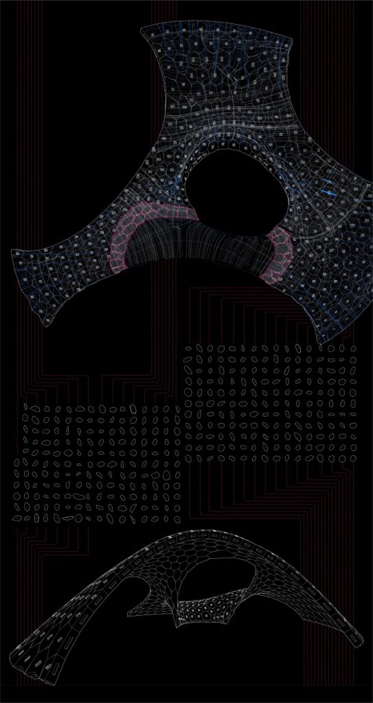
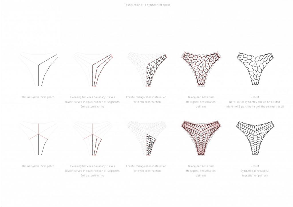
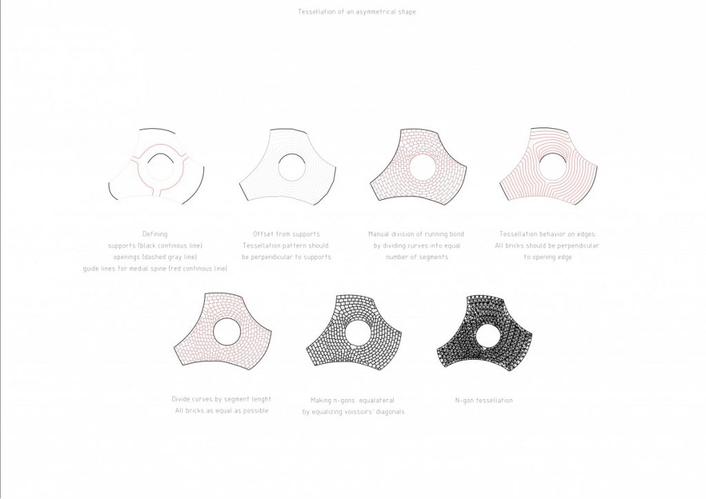
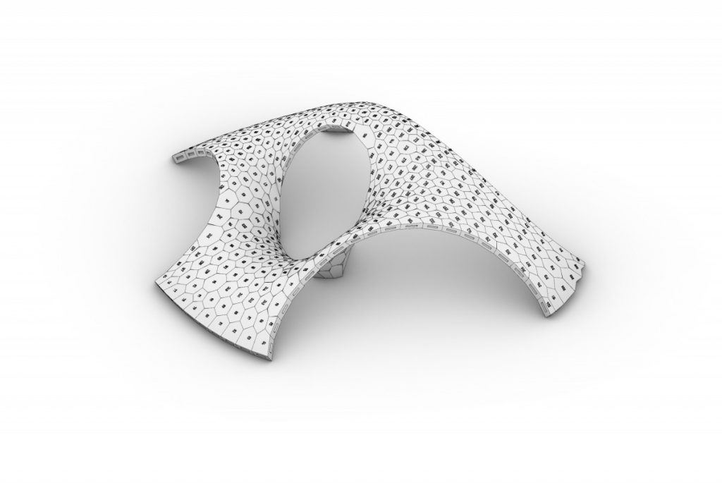
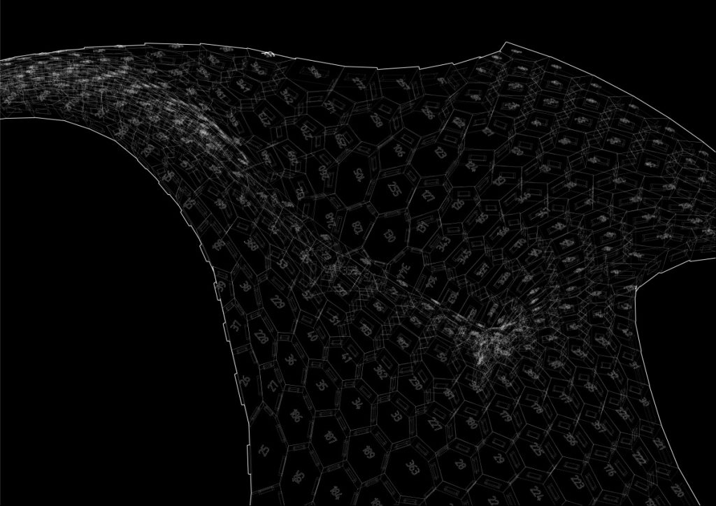
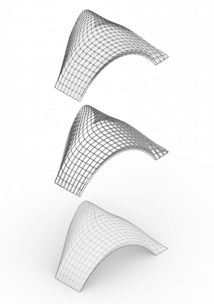
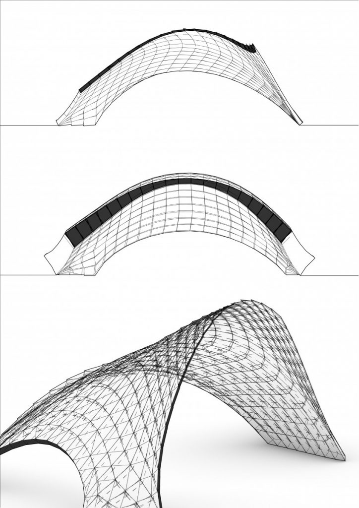
Discrete element assemblies, double curved surfaces, shell structures, mesh tessellation and digital production

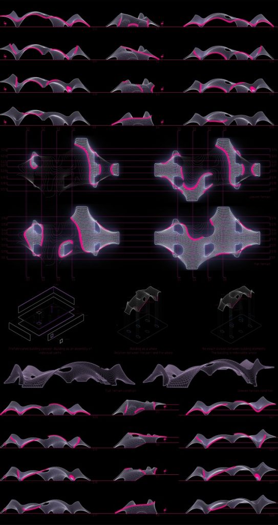
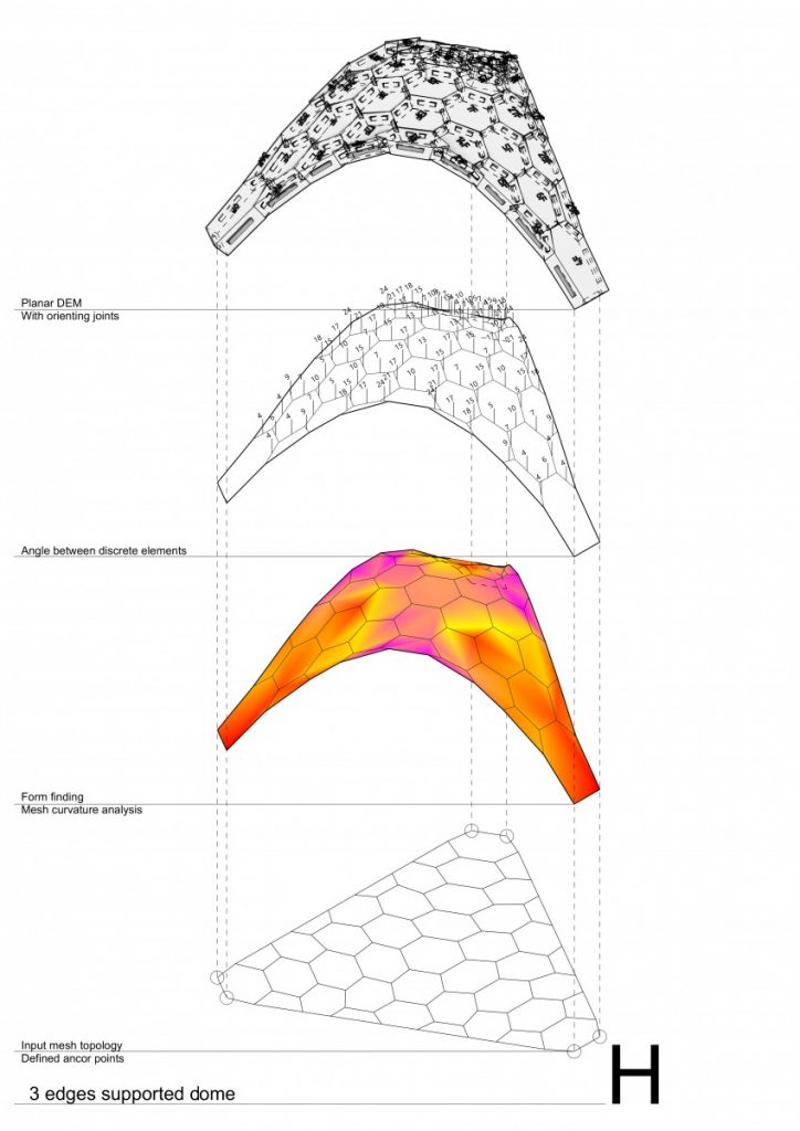
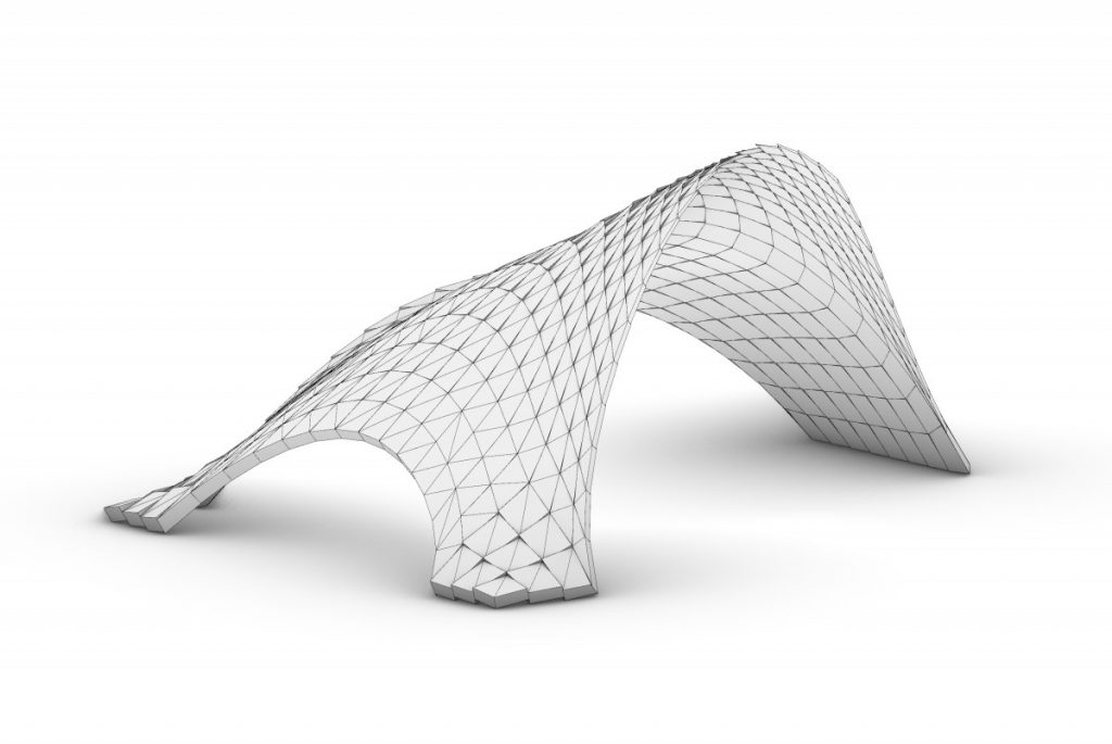
This master thesis is a research based project which explores compression-only based structures, covering such subtitles as – discrete element assemblies, double curved surfaces, shell structures, mesh tessellation of symmetrical and asymmetrical geometry together with digital production used for testing structural behavior of masonry structures.
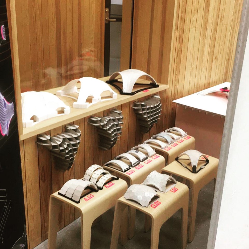
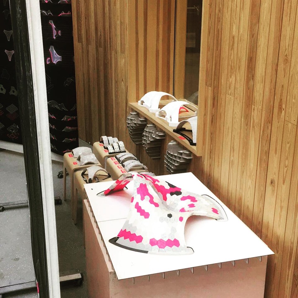
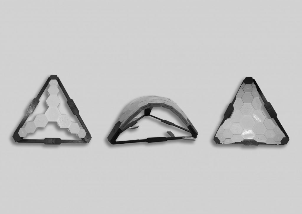
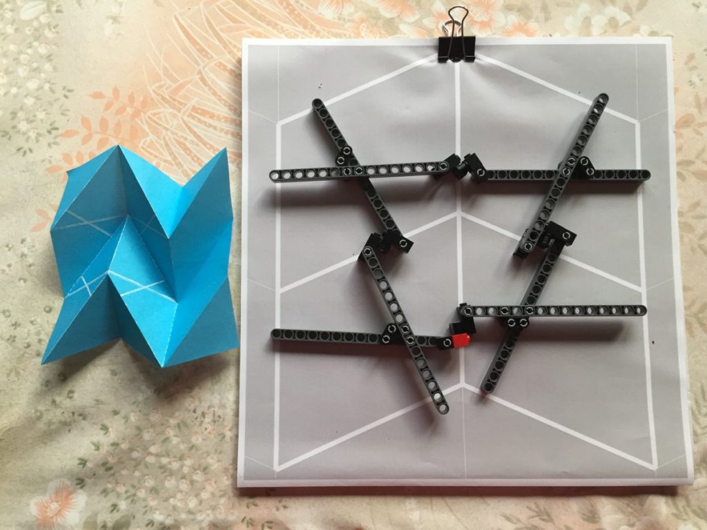
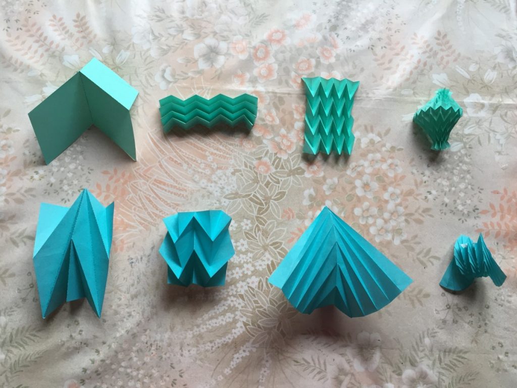
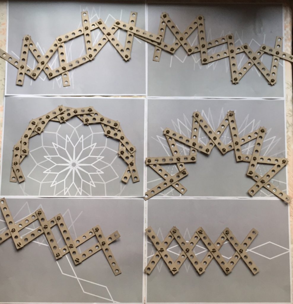
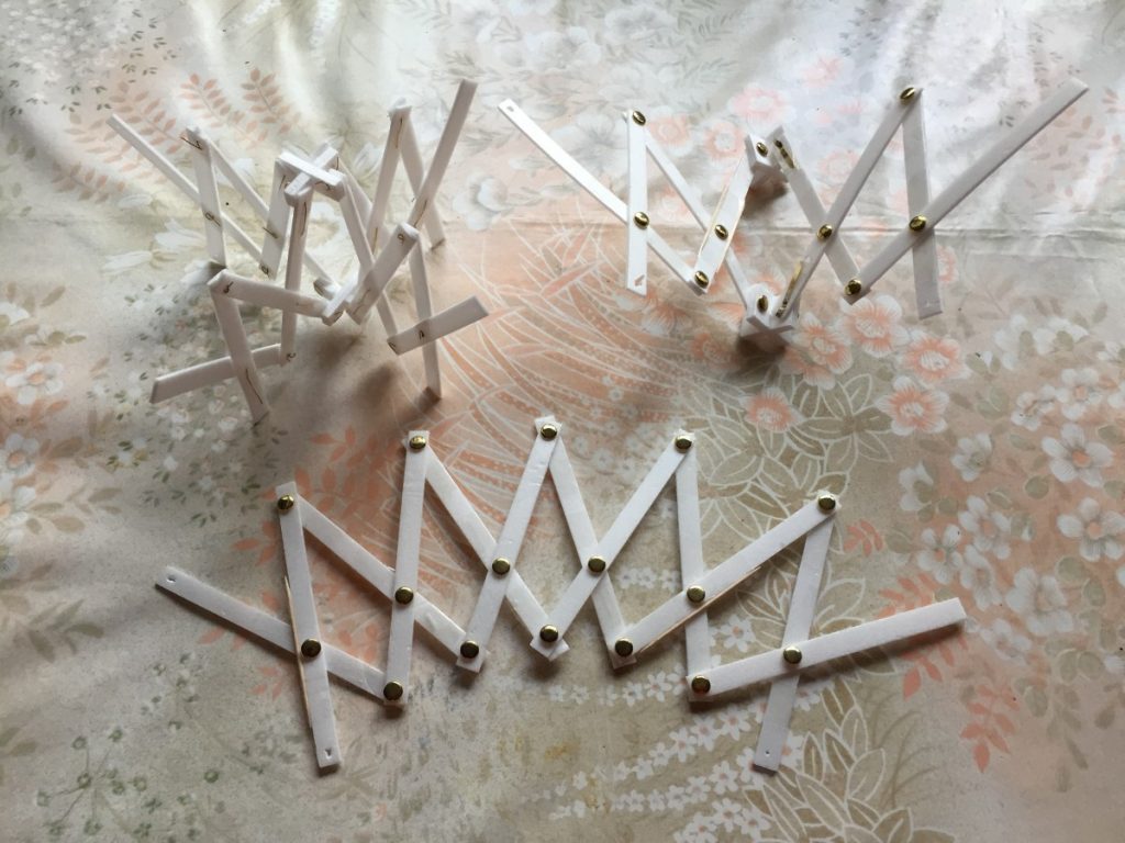
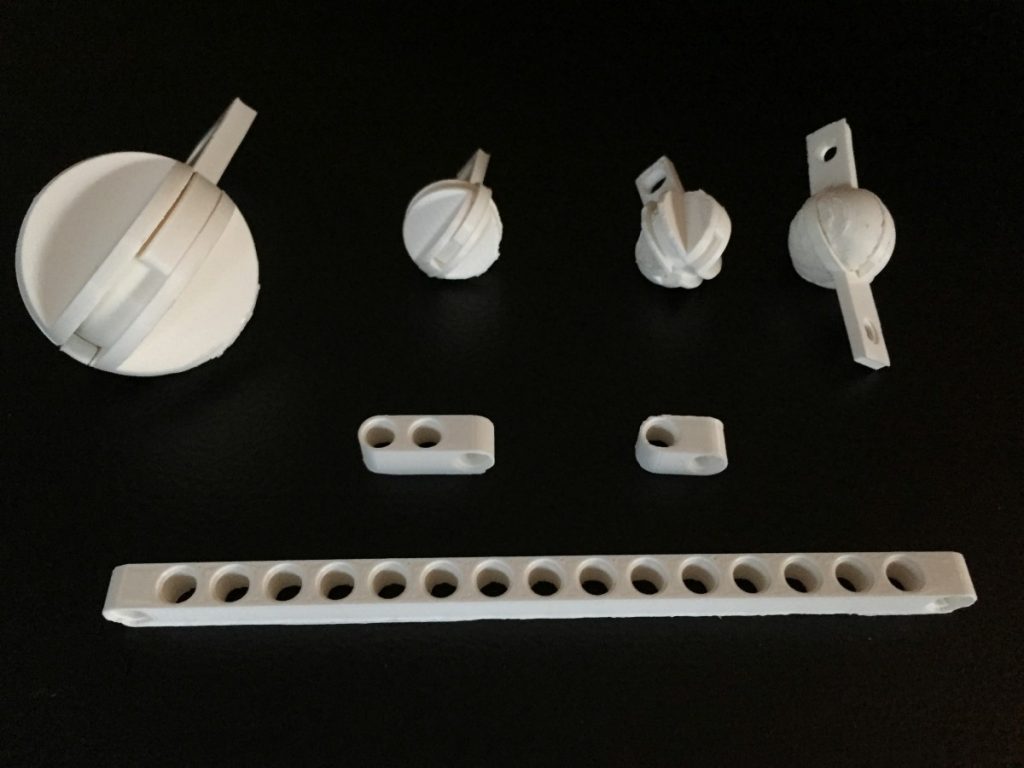
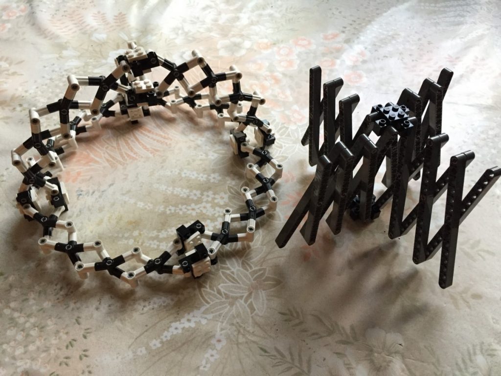
The background of the current research project was based on the works of Block Research Group. During this stage two different softwares were analyzed in comparison to each other (RhinoVault and Kangaroo2 for grasshopper) and the physical model of both structures was made. First experiments as compression-only based physical models were 3D printed from PLA and failed. Moving forward the further research methodology was developed – to start testing from simple structures – like arches and step by step by adding different variables explore the complex systems such as vaults, domes both single and double curved and finally – symmetry and asymmetry. This comprehensive analysis from the simplest element – arch to the most complicated sample – asymmetrical free form vault helped to deepen an understanding of behavior of such structures while testing the impact of thickness, curvature degree and curvature type, tessellation type and joints between the elements design.
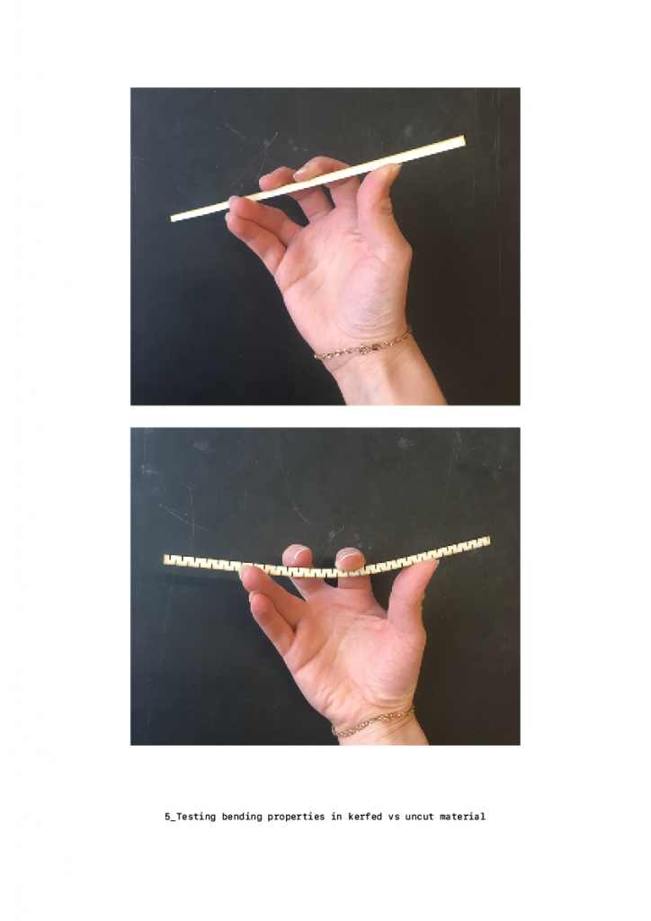
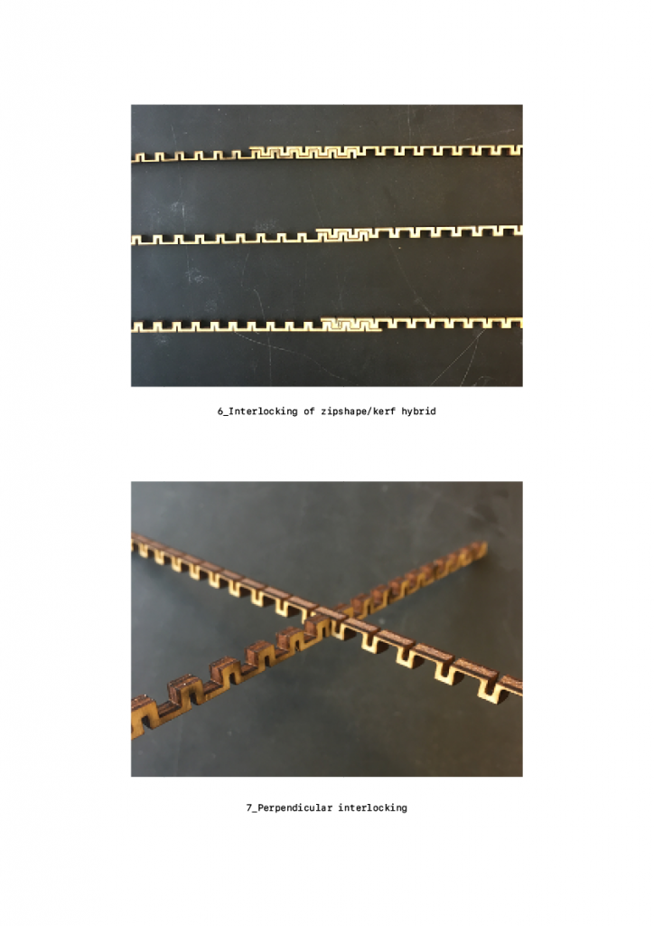
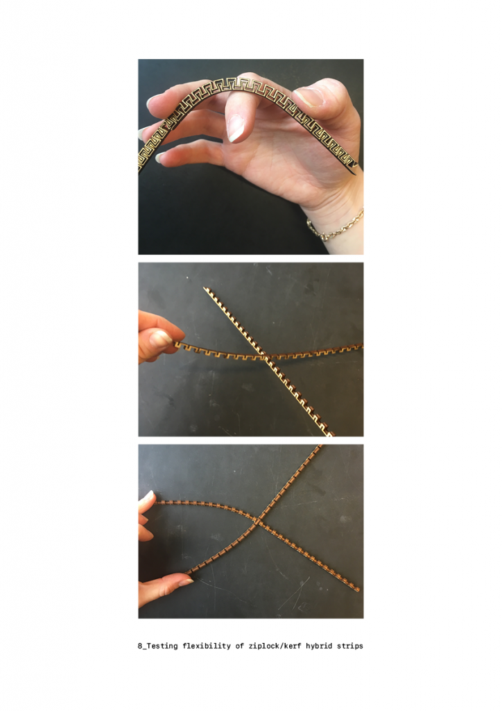
Furthermore, project covers digital production and fast prototyping techniques – 3D modelling, parametric modelling and 3D printing together with all challenges which can occur during translation of digital model into the physical model.
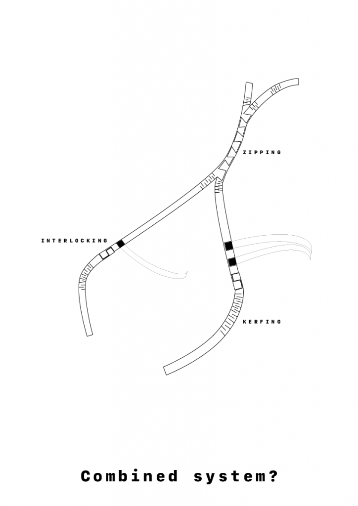
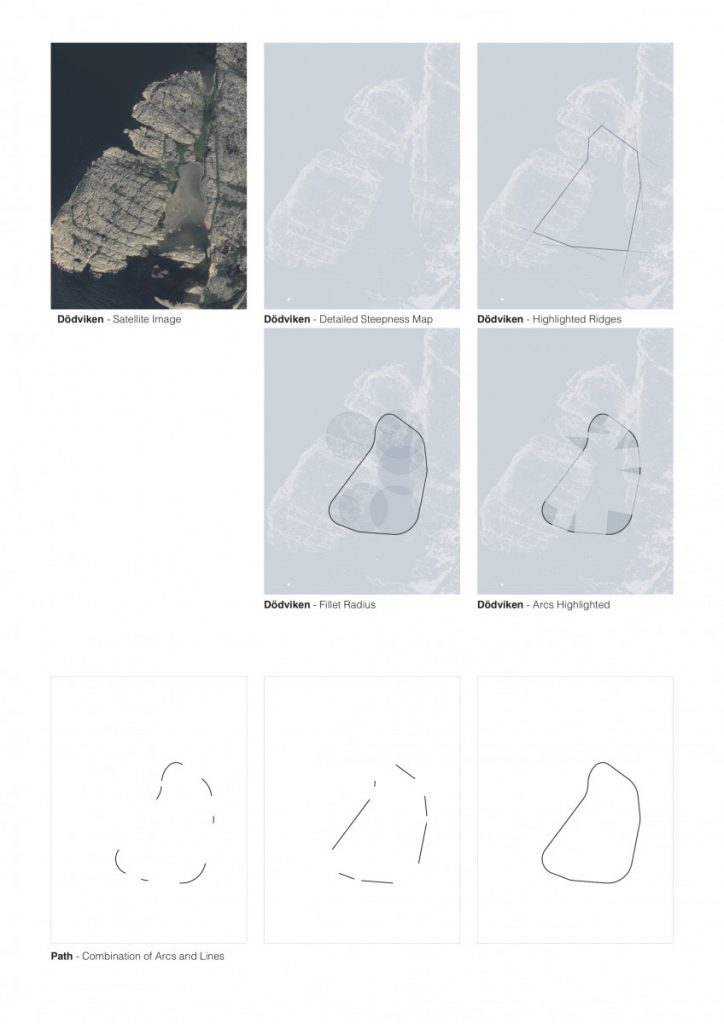
Conclusions of the research project and implementation into the architectural field are proposed as analysis of adaptation to flat and uneven terrain, together with the analysis of different possible combinations of shell structures into the one whole system called mereology – in philosophy and mathematical logic, mereology is the study of parts and the wholes they form.

P4.T2.Movement

As we moved onto task 2, I started analysing forms of the linkages and combining two sets to test the spatial properties they exhibited.

The rotation of the linkages needed to exhibit some form or motion and resulting change that would offer a variation in form and surface and space, as in the previous study of the kaleidocycle.

The servo was mounted to a clear acrylic frame and I began to run tests of forms using the basic principle of the four bar linkage.

As observed from the tests above, the spatial study extended only to planar elements. I began incorporating rotation and folds to allow for movement in 3 dimensions and multiple axis for each linkage. Both sets of studies provide grounds for further exploration but I will need to be more intentional in the variation of parameters of the subject.

P4.T1.Linkages

Project 04 saw a move to material prototyping and developing a methodology for building three dimensional forms. I looked into Frei Ottos fabric tensile structures as well as engineer Vladimir Shukhovs steel tensile structures as precedent.

Keeping the automated robotic theme running I also decided to incorporate a servo motor into my design process. This brought a moving element to the prototyping and prompted the research into the umbrella mechanism and three/ four point linkages.

I also explored the Kaleidocycle (flexagon) which are models of linked tetrahedra which turn through their centres. I wanted to incorporate these methods for materials that, through their connection, could change form and produce multiple spatial environments.

Converging-limited foldability

I tried to explore some of the possibilities from folding a piece of paper while constraining with various “levels of freedom”. The following diagrams explain the results from different limiting points and how they can be reproduced with one foldable element. By introducing the limiting plane the original constraining points are removed but the folding results are attained.

Zip, Kerf, Interlock – Wood Bending Tests

After working with swarming agents that produced linear curves in the first part of this project, I decided that I wanted to continue exploring linear shapes further in the fabrication part of the process.

One of the first things I tried during the week was make simplified interpretations of some of the shapes produced during the previous part of the project using strips of paper. However, since the thickness of paper is negligible, it has properties and a flexibility that no full-scale material can emulate. This led me to choose a more specific material to have in mind when continuing the testing. I chose to research wood, and different methods that can be used to make wood flexible.

In summary, I have explored three methods of working with wood to produce flexible, three-dimensional shapes. These methods are zipping (based on a concept by Schindlersalmerón), kerfing and interlocking.

Using the laser cutter and 4 mm thick poplar wood sheets, I have experimented with different operations that produce different kinds of flexible beam-like strips.

Next, I will look into combining the different processing methods to create a more complex system where the different possibilities and limitations of the three methods can support each other. I also have to narrow the investigation down from a system that can ”do anything” to a more specific part of the site and program.

Clustered results

Quite often architects are challenged with the need to analyze large sets of data in the design process. However, there is a lack of defined approaches and therefore in most cases detailed analyses are avoided. Through this project I tried to observe a fraction of what could be used as a valuable assessment tool in various projects. Clustering approaches are not uncommon in different fields when in need to observe data, but in architecture these have been poorly investigated. I have used the MATLAB programming language developed by MathWorks to investigate the potential for architectural use.

This is a brief description of the steps in the process:

1. Looking at the height maps as a set of pixels containing height data and clustering with kmeans. (This is an unsupervised learning technique that does the analysis without predefined criteria.) The results give groups of heights that share similar ‘intensity’.

2. A region of interest is selected with clustering division at k=5.

3. Radiation maps of the site are generated using Ladybug. (Different relevant maps or parameters can be used for evaluation depending on the requirements.)

4. k-means clustering is applied on a radiation map. The points that satisfy values above a defined threshold are selected and interpolated to the previously defined region of interest. This gives points that satisfy certain irradiation criteria within the specified height region.

5. New clusters are created in order to define optimal building areas and building shapes are defined at locations where the points satisfy certain density.

The results from the steps are shown in the following isometric drawing.

An experiment with varying k-number values in the kmeans clustering was performed and the results can be observed in the short animation. For values above 200 it is difficult to read the information from the resulting images, but lower k-numbers can give different levels of detail depending on the requirements of the user.

Discrete element assemblies, shell structures, curved surfaces, tessellation

Further development of the thesis project – testing 3 supports supported dome structure worked. Although the side elements tend to fall away and do not have any structural performance in the whole model.

Having a medial spine helps during the assembly process and once it is assembled all other elements can be easily attached to each other.

Documenting symmetrical 3 supports supported dome structure with hexagonal tessellation pattern

Some additional information according to the tessellation of symmetrical and asymmetrical shell structures could be found in the diagrams below.

Tessellation of a symmetrical shell
Tessellation of an asymmetrical shell

While working with symmetry gives an opportunity to automate the process in Grasshopper, working with an asymmetrical shapes requires some background knowledge, starting from medial spine to understanding of a force flow in the discrete element shell geometry to size of each voussoir and as for now is drawn manually. Furthermore, it is impossible to stick with a same number of vertexes for each detail, so the whole tessellation becomes an n-gon pattern.

Final model for testing asymmetrical discrete element shell on a flat terrain condition, size – 70x70x20cm, number of elements ~380 pieces.
Fragment of an asymmetrical model on a flat terrain condition
Layout of details

And finally first experiments with different thickness of a shell from DE.

Mesh offset by face normals using remaped amplitude
Scheme showing the different thickness of a shell having the thicker supports and thinner top elements

Wrapping it up

I took a step back and tried to more clearly explain how the path is generated, by breaking it down step by step. The fact that the curve is made up of lines and arcs gives me an opportunity to arrange elements of the program accordingly. Arcs would be “stops” along the path where things happen, and lines would form connections, both physical and infrastructural, between stops.

I have also continued to look at the spaces above and below the level of the path. This becomes clearer in this axonometric showing the path appearing and disappearing with the landscape.


By looking at the relationship between the plan and the section, and then the section and the plan, I have begun to analyse their characteristics and place elements of the program along the route. The section below shows the unwrapped route split into curved/straight and above/below segments, alongside the plan.

Here is a diagram attempting to explain certain elements of the campsite along the route.

Generating architectural shapes and stepping out of my comfort zone – final thoughts about P3

For the final stage of the first part of this project, I have experimented further with combining different meshes and settings for the agents in Culebra to see what architectural shapes can be generated based on different criteria. I produced a series of 25 architectural shapes/pavillions, intuitively testing different settings to generate different architectural elements. After generating the pavillions, I zoomed in on them to identify different architectural elements/typologies that had emerged based on different settings.

My usual process when working with architectural projects is quite rational and controlled. Trying to let go of my own expectations for what the end result will be has been a challenge for me during this project. During my presentation, I got the comment that I from here on should try to take a step back to a more rational, controlled process and set of rules for the Culebra agents. Getting that comment was a big victory for me, as proof that I managed to step outside of my regulated and boxy comfort zone and just try something new based on intuition. I am very much looking forward to the next part of the project, since I hopefully will get a chance to keep working on finding the balance between controlled/rational/result-oriented and intuitive design processes.