Continuous columns.

Glasspool_Jack_Project02_FinalBoards

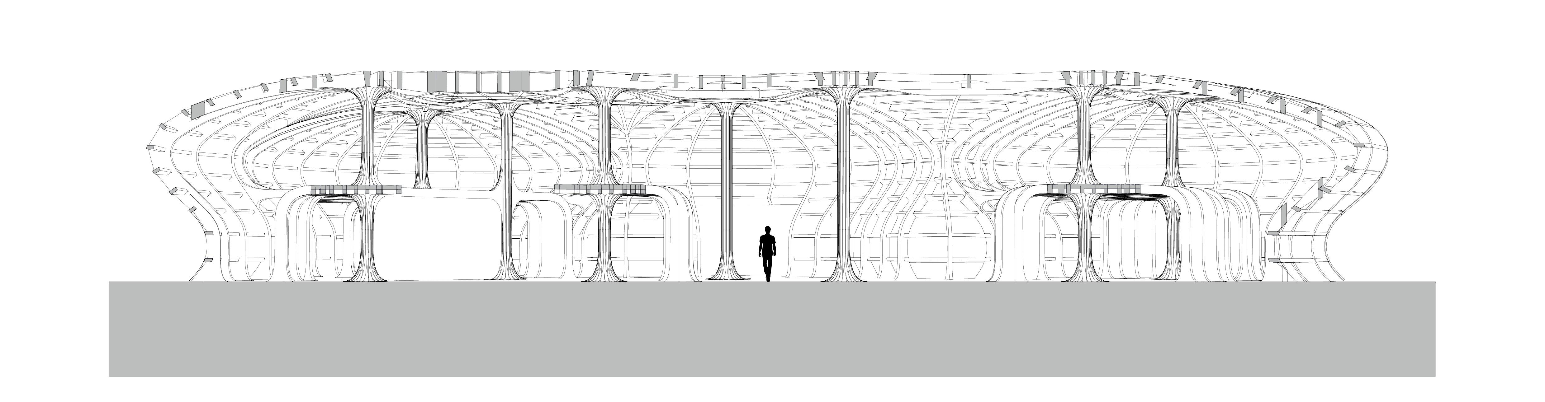
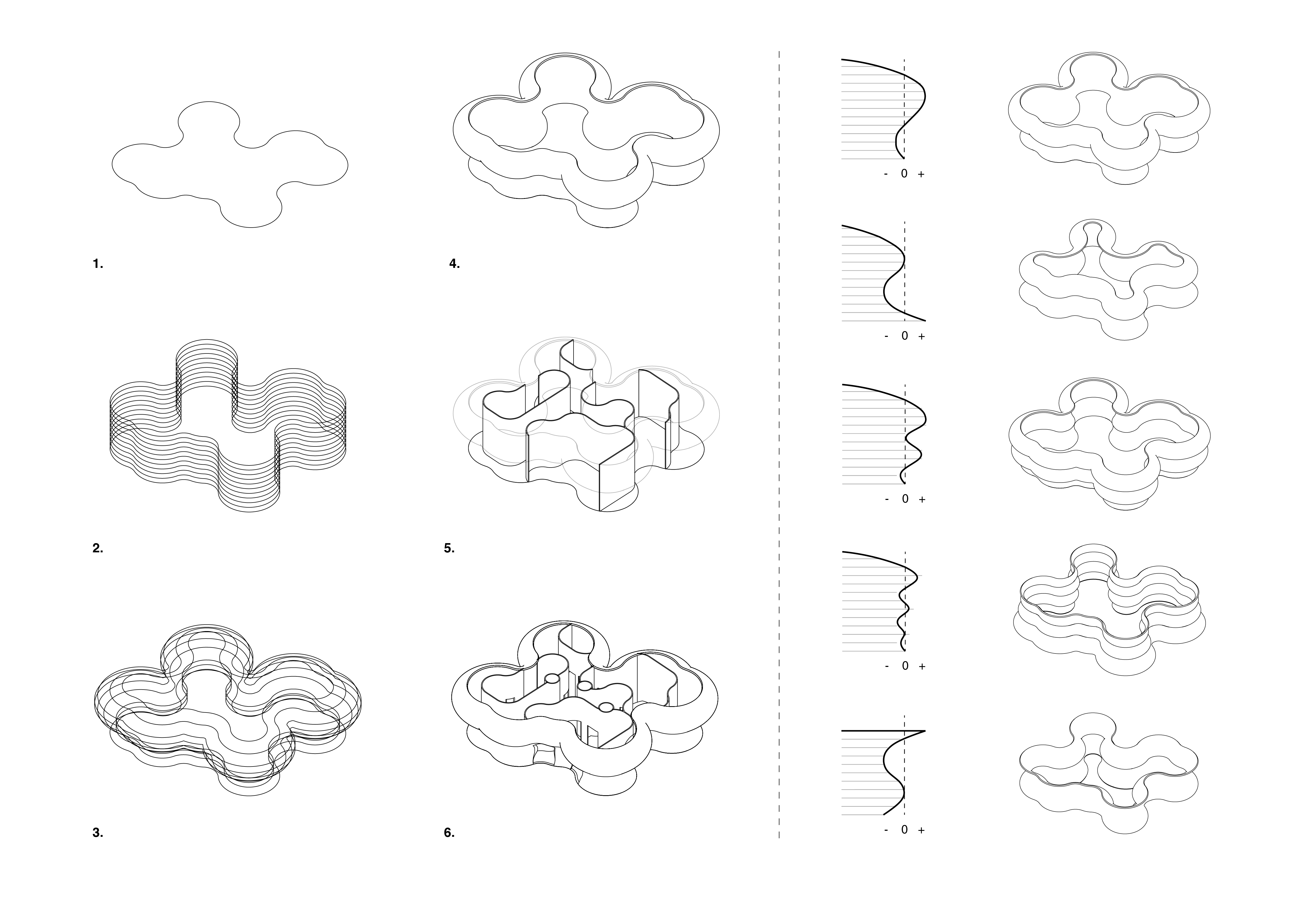
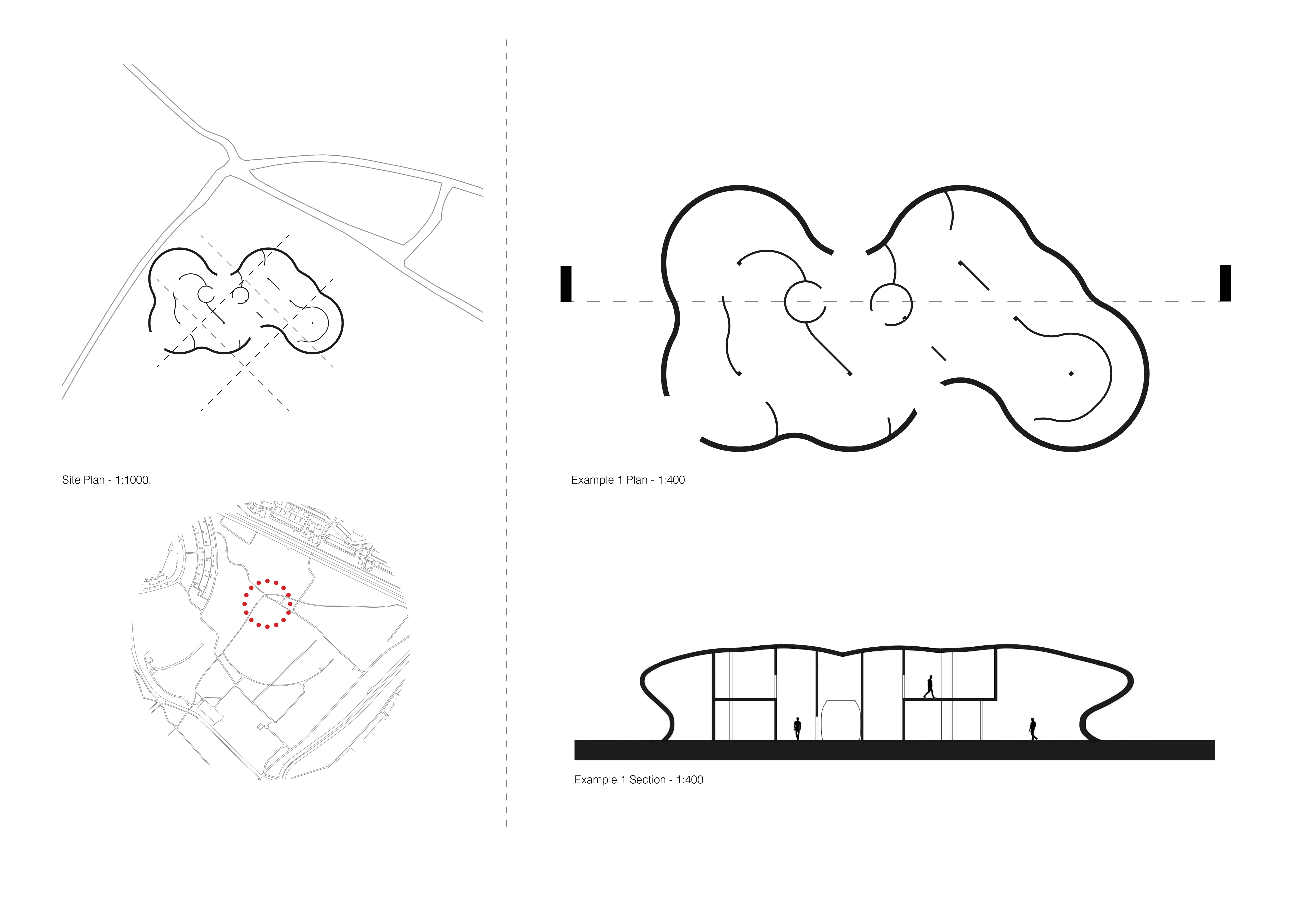
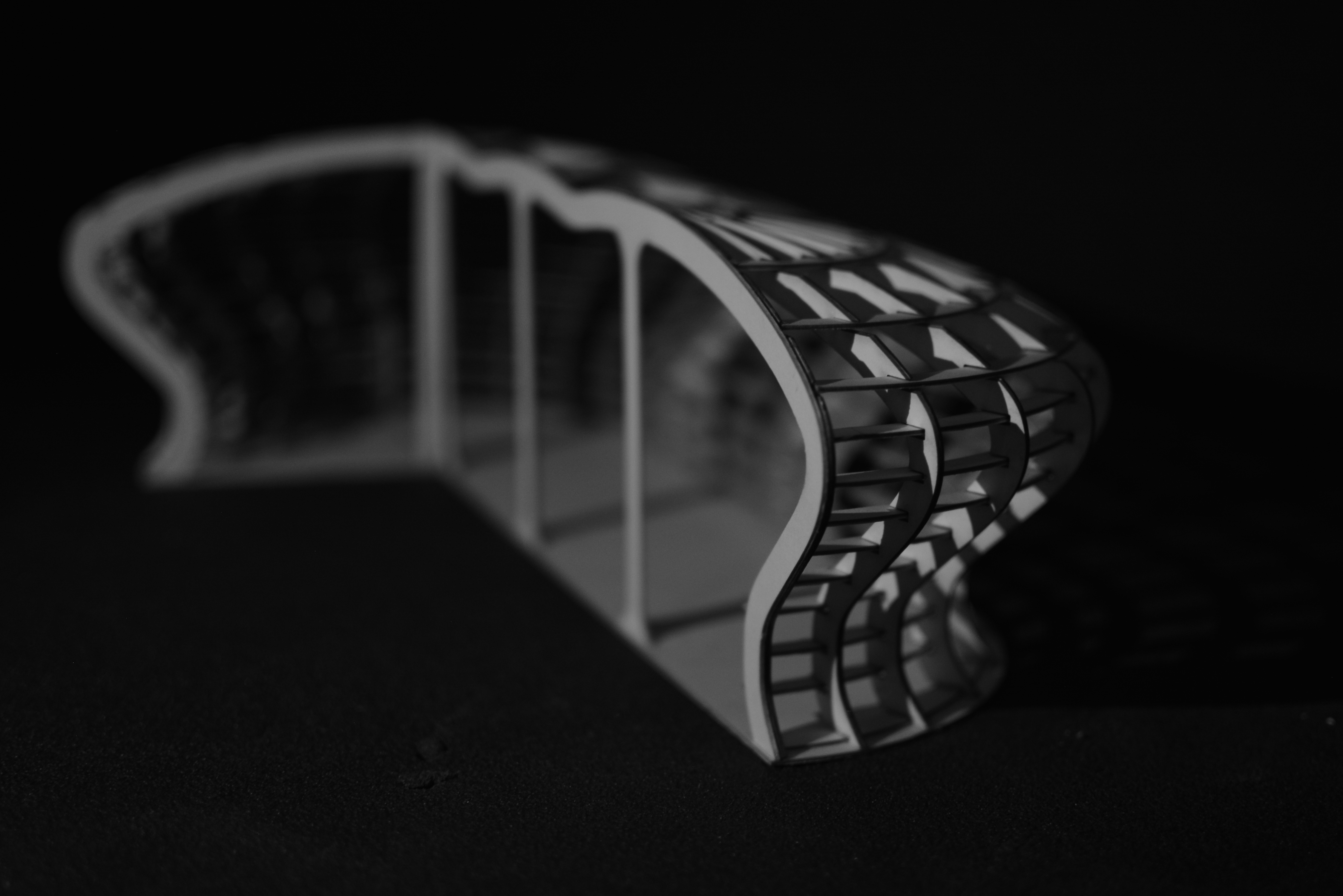
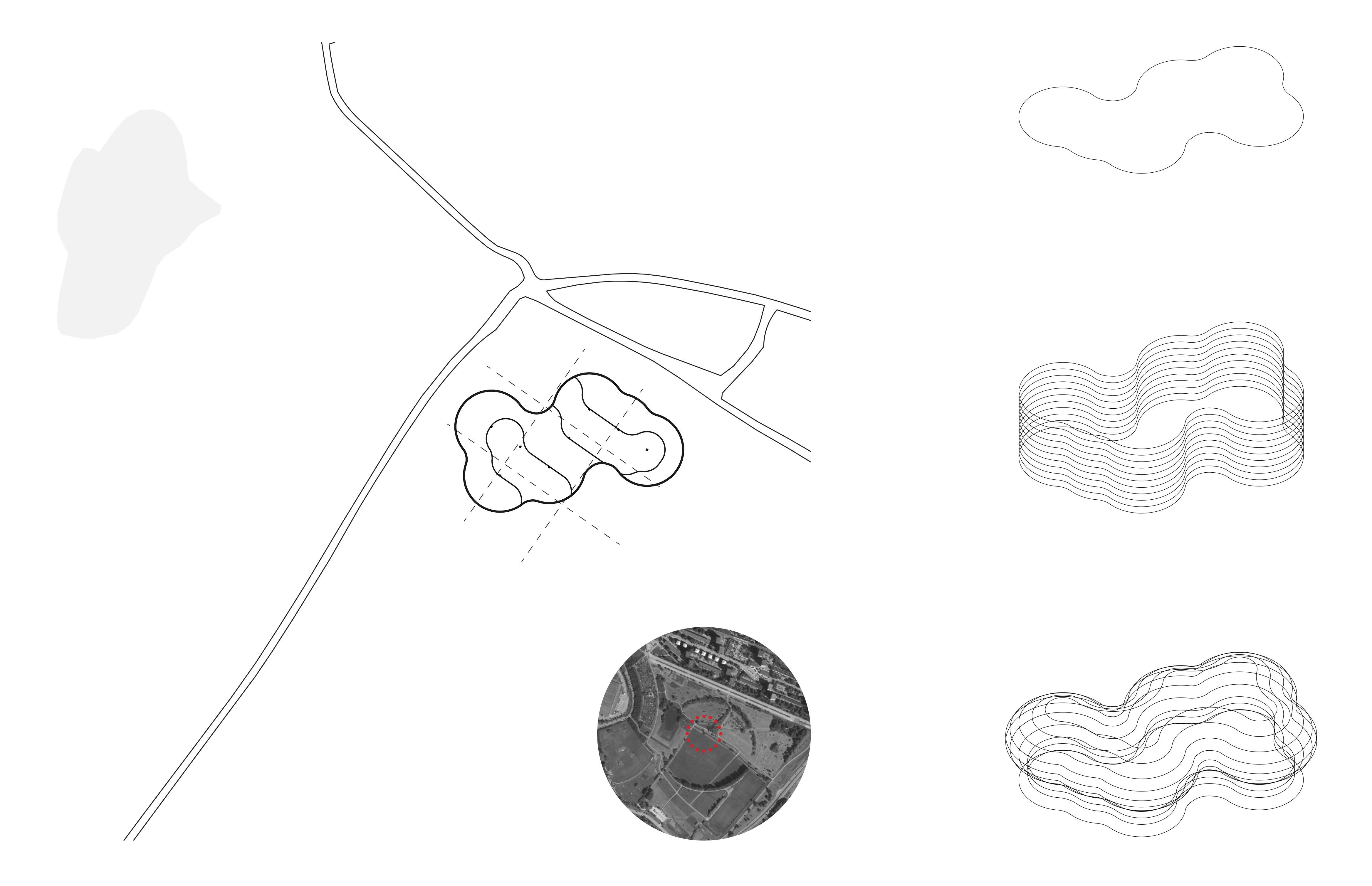
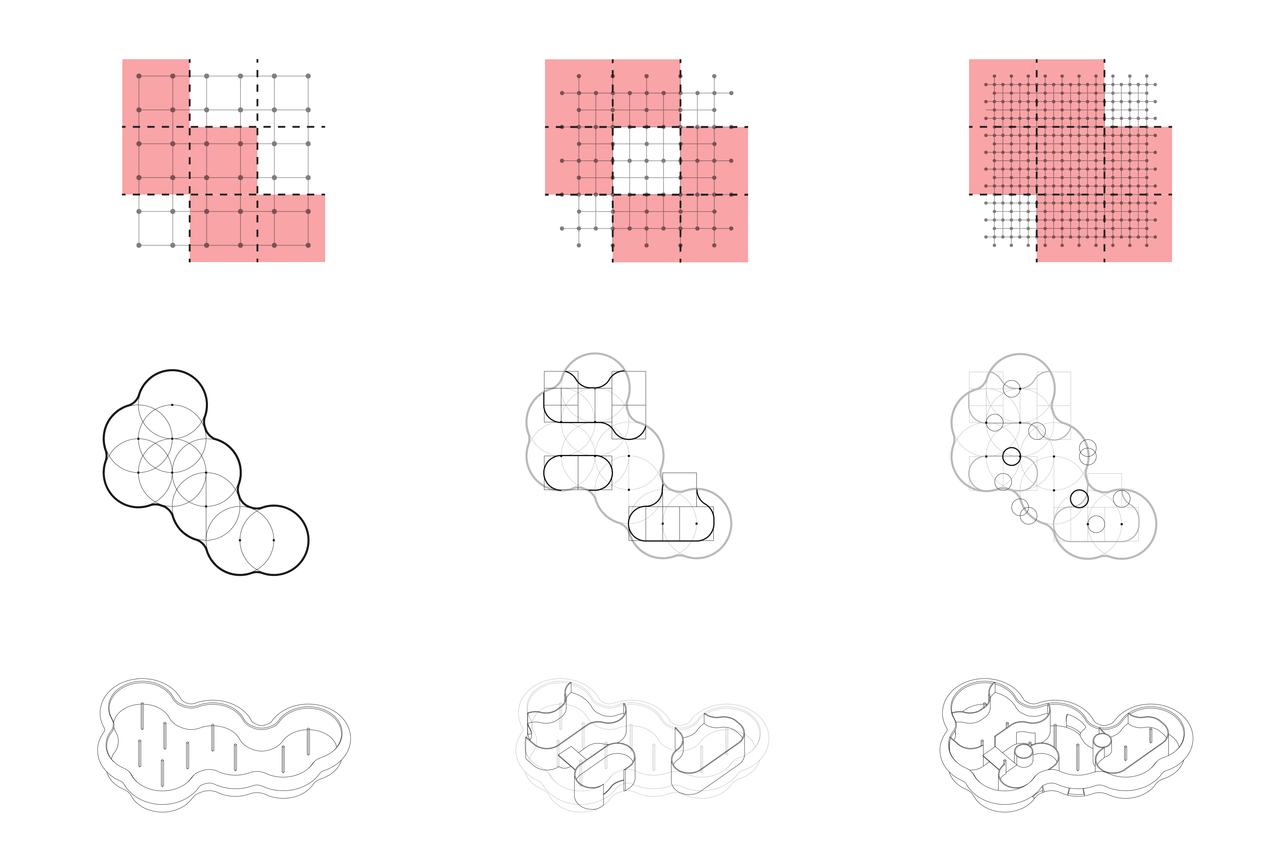
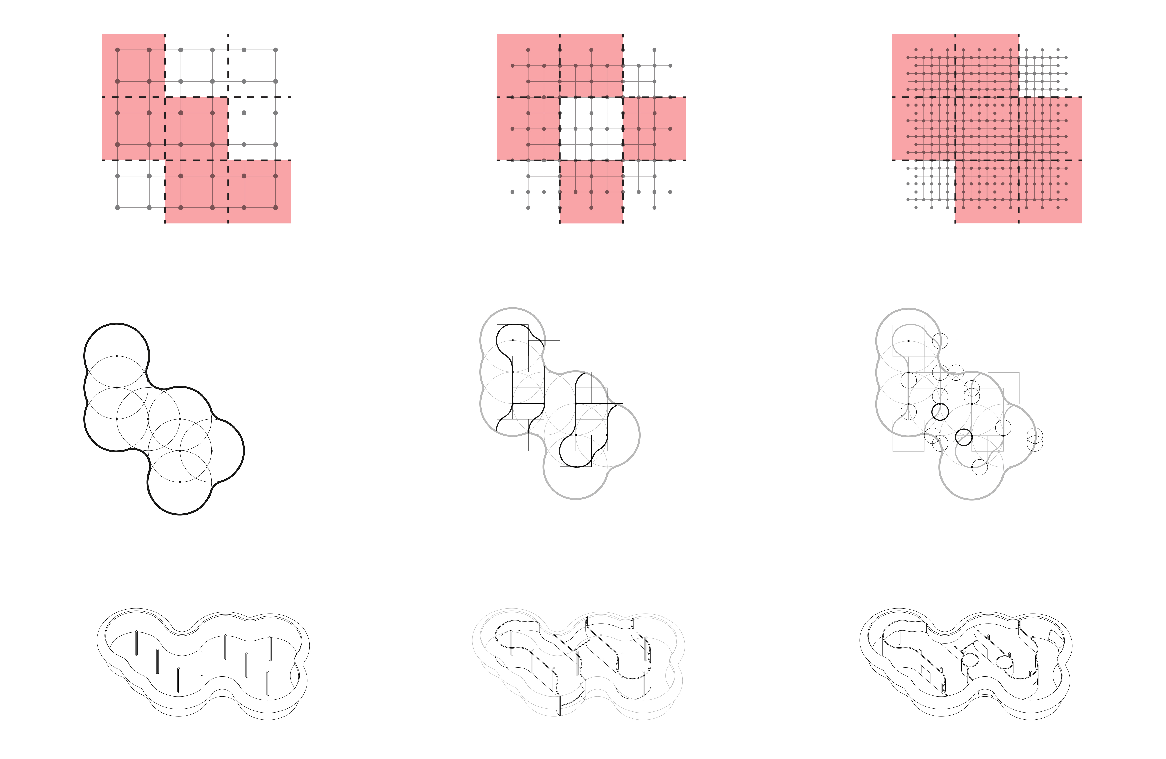
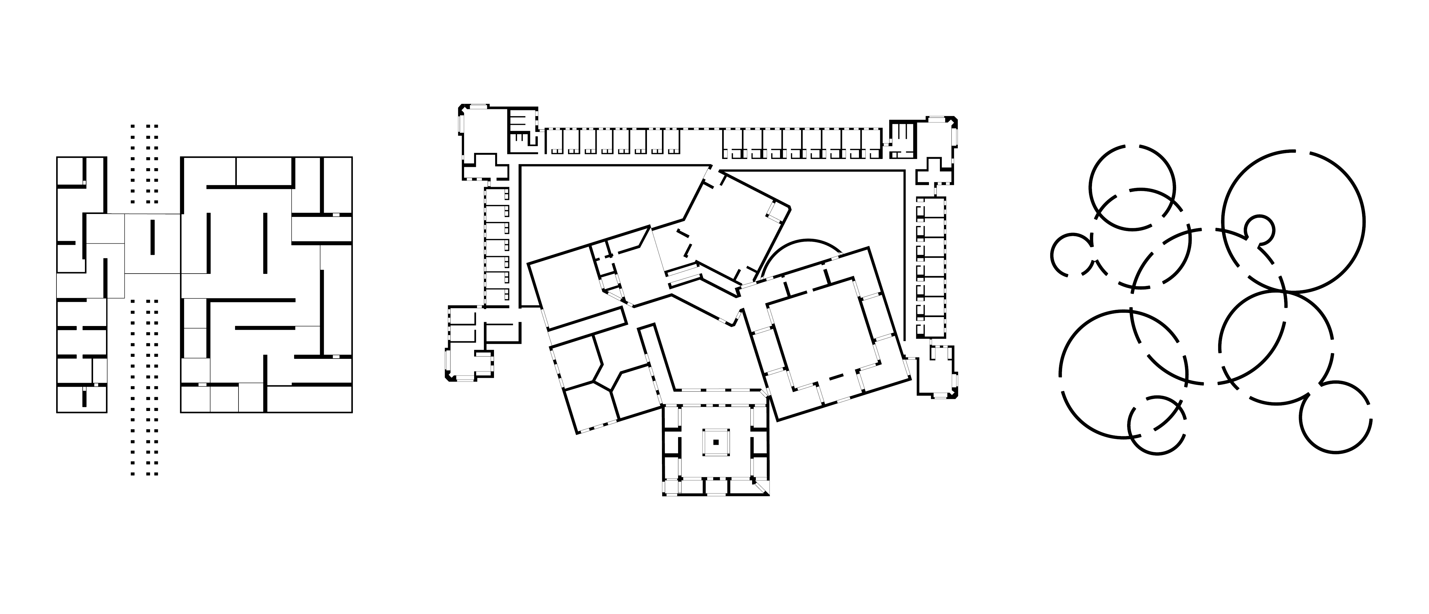
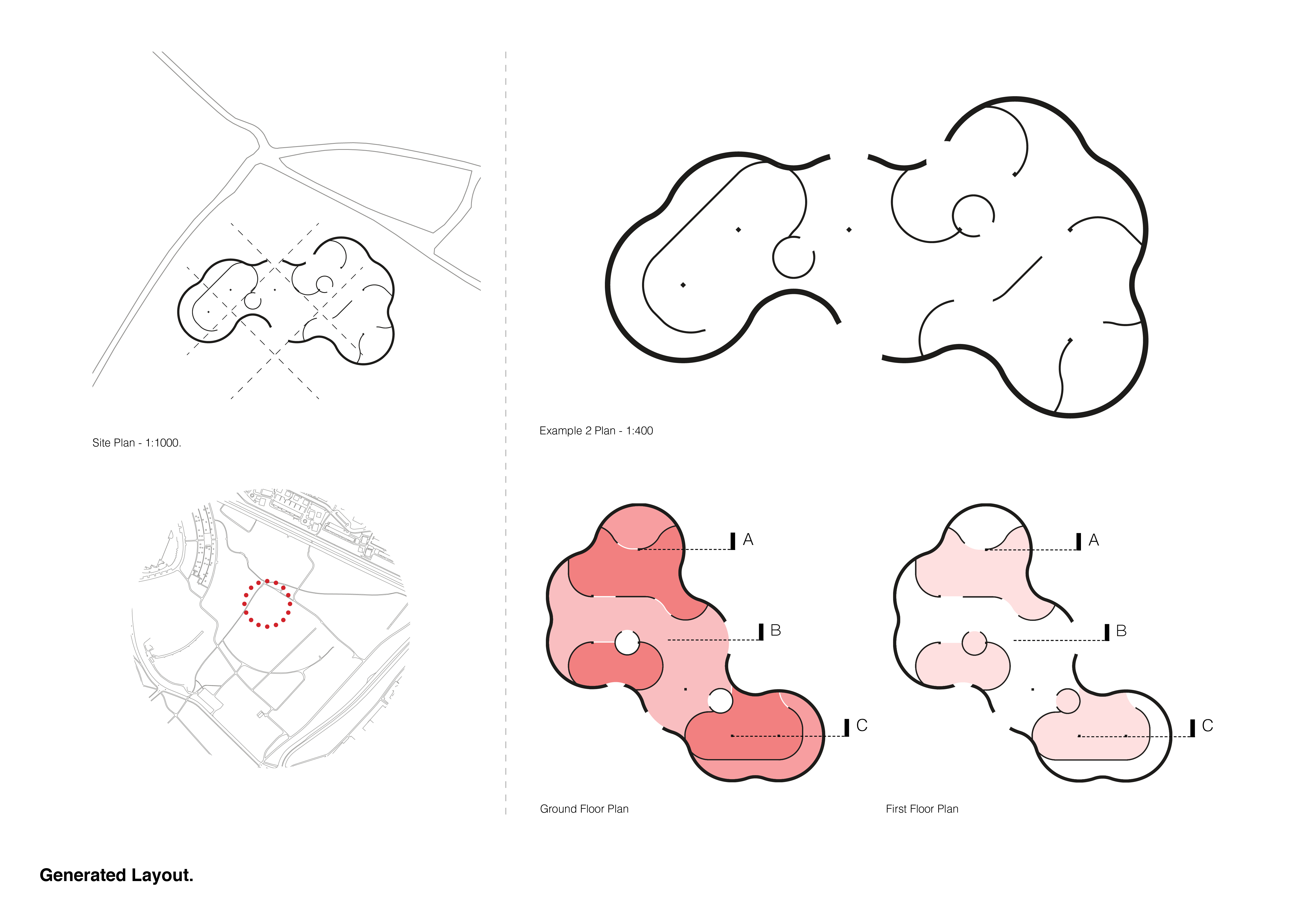
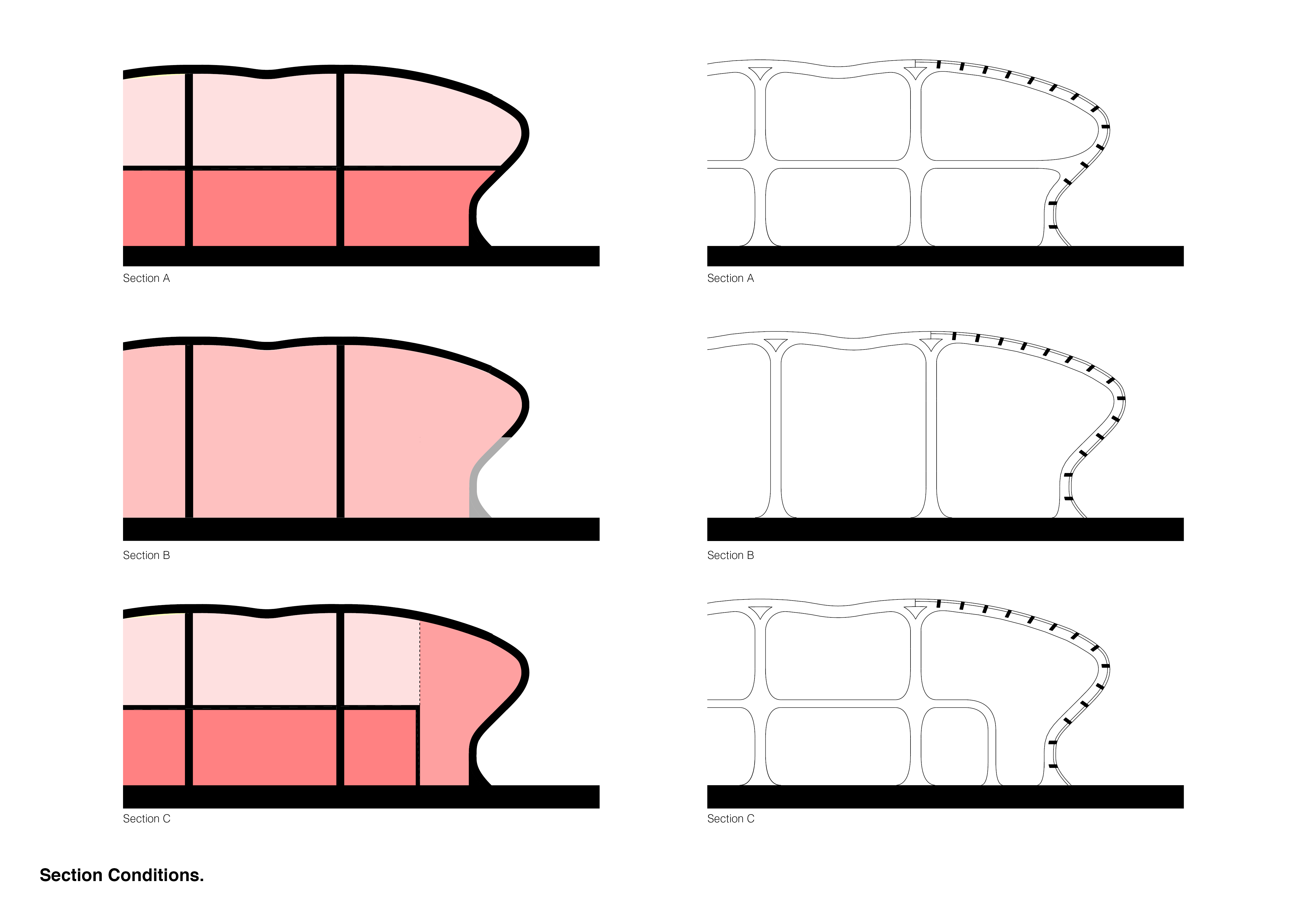
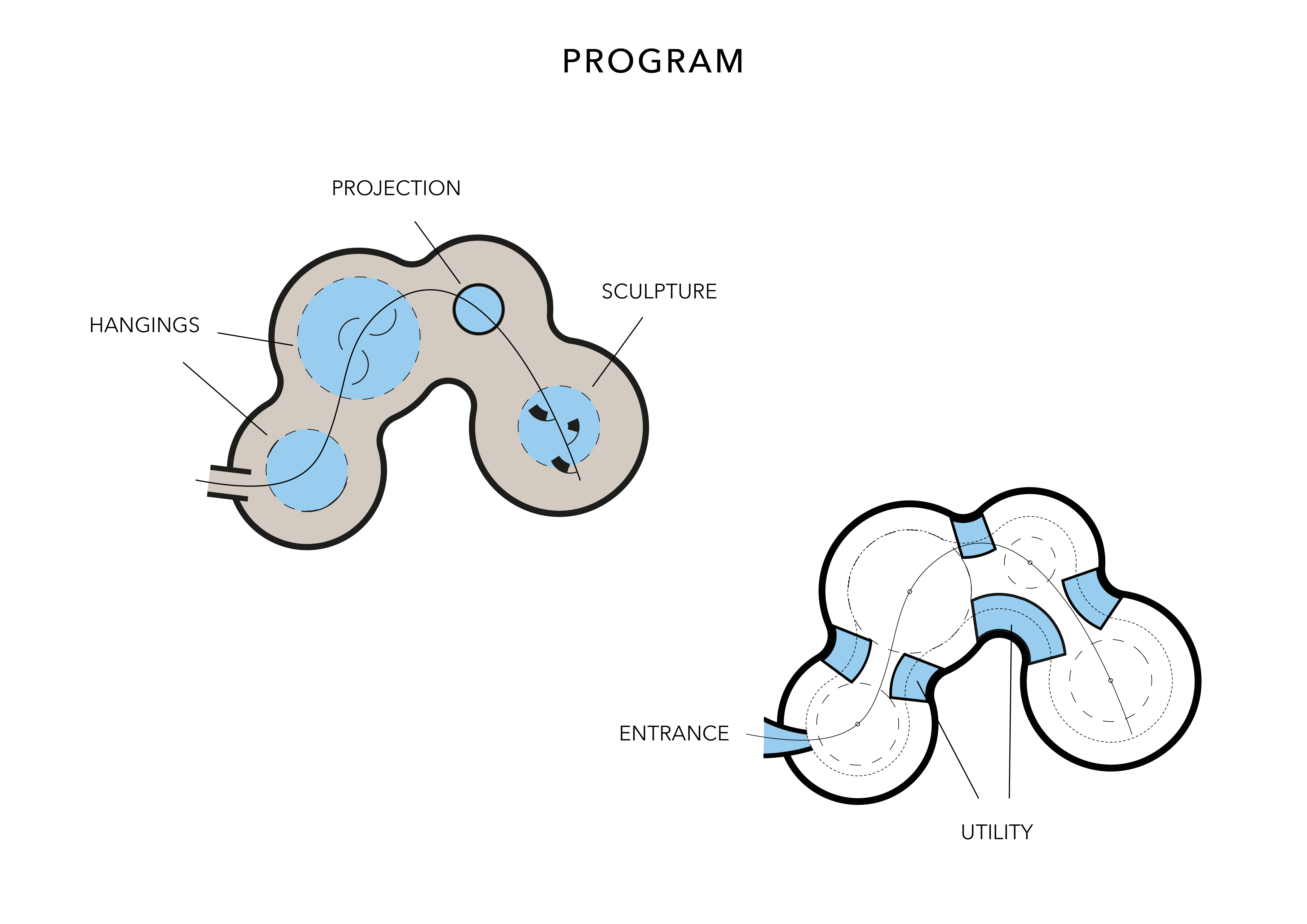
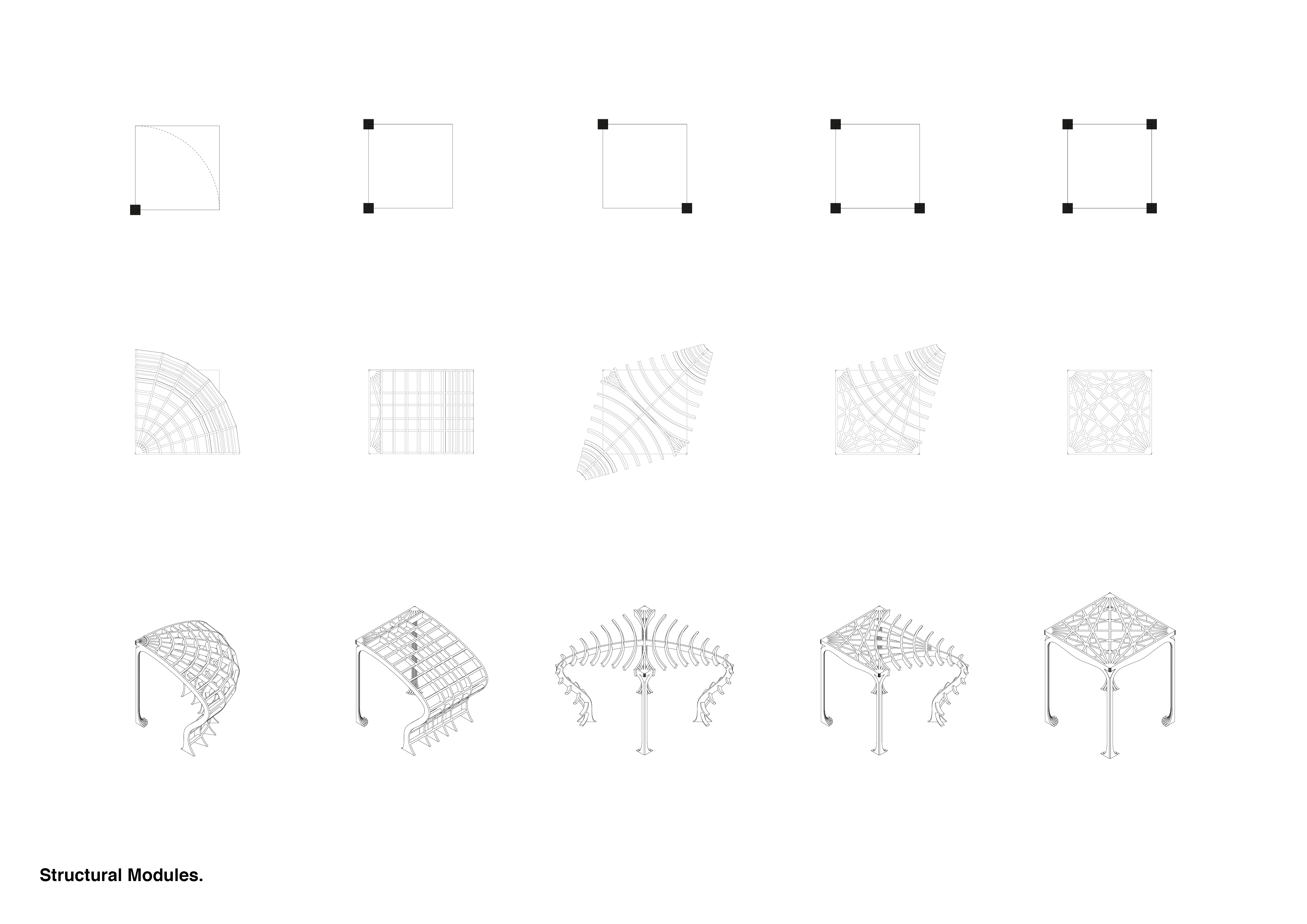
To develop my original generated Python plan into a 3D structure, I began by analysing sectional and spatial conditions. Dividing the plan into three key sections I identified the key spaces. The structure of the section followed the original generated curve which remained consistent throughout the building. The big difference occurred internally when the interior sections interacted with the outer frame. I looked at the key intersections and adapted these in section so the language internally was consistent with the external.

Glasspool_Jack_Project02_FinalBoards2

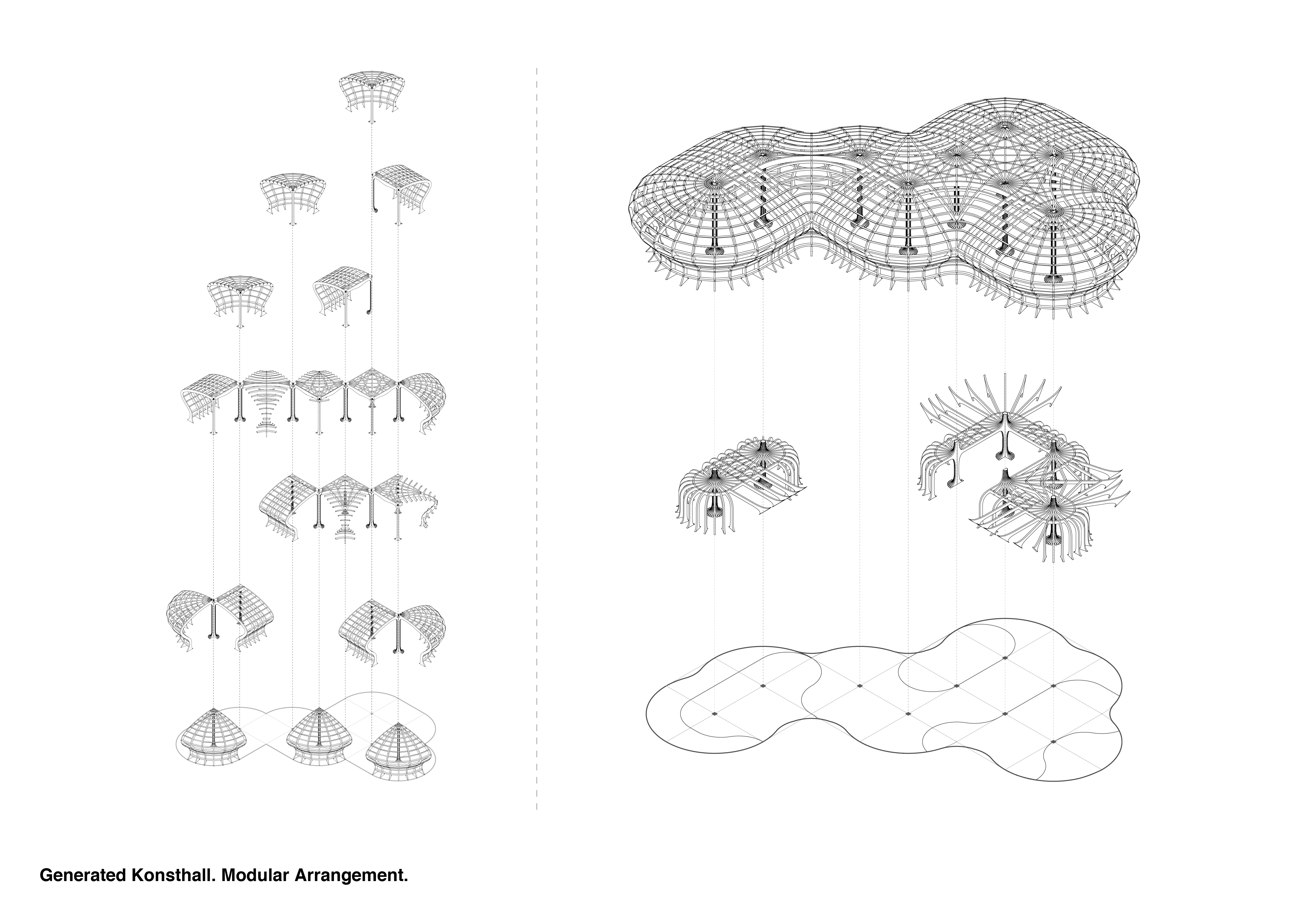
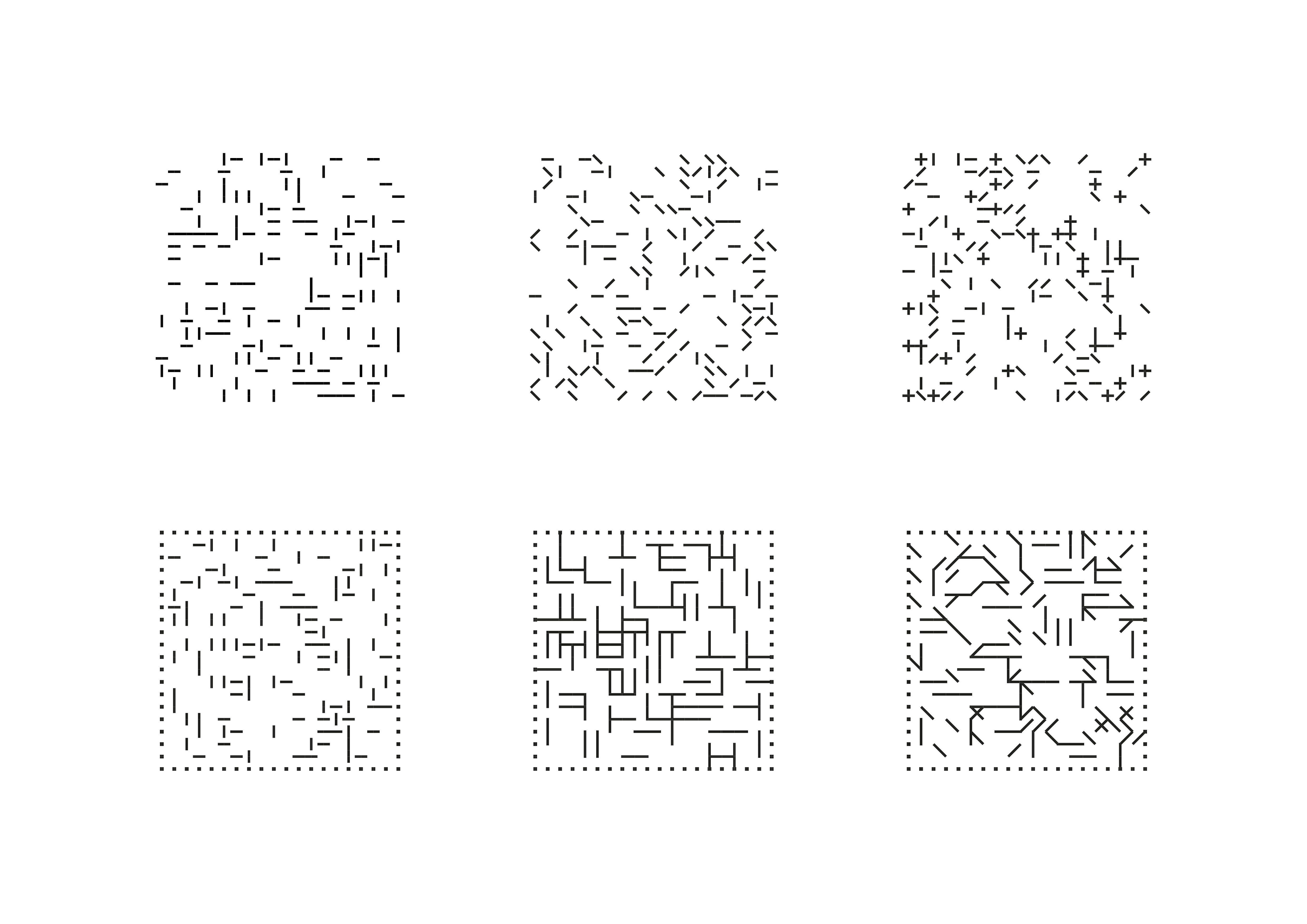
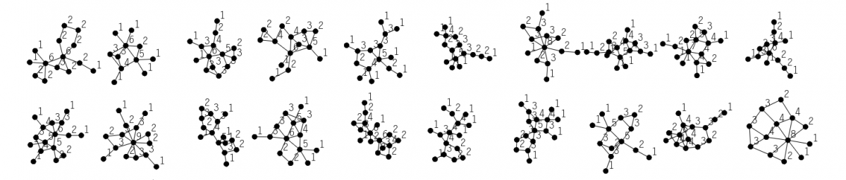
Looking at these sectional pieces further I listed out all the varying arrangements of the sections to develop a list of modules which when orientated according to the generated plan could begin to form the undulating structure of the building.Glasspool_Jack_Project02_FinalBoards3

DSC_0609


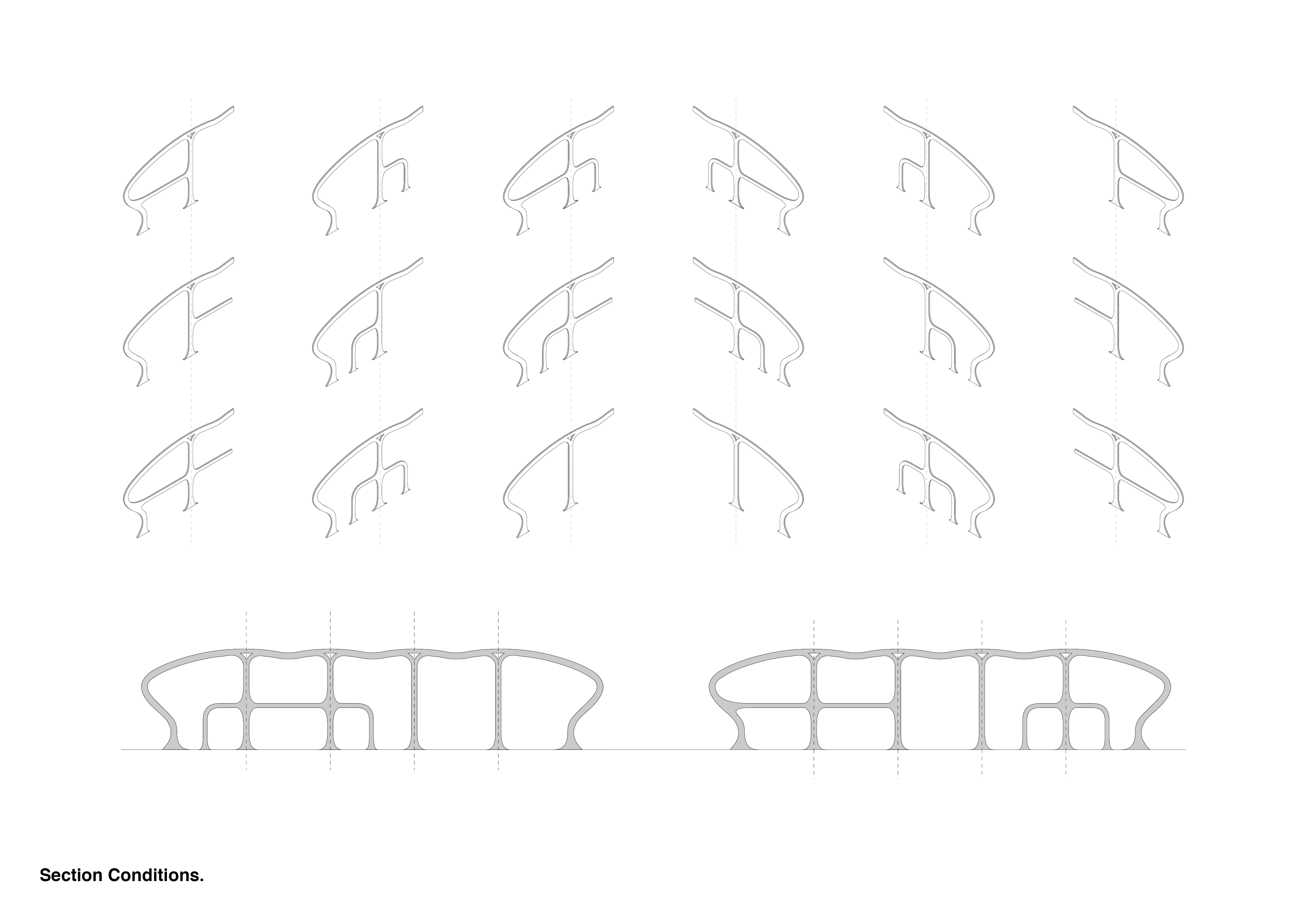
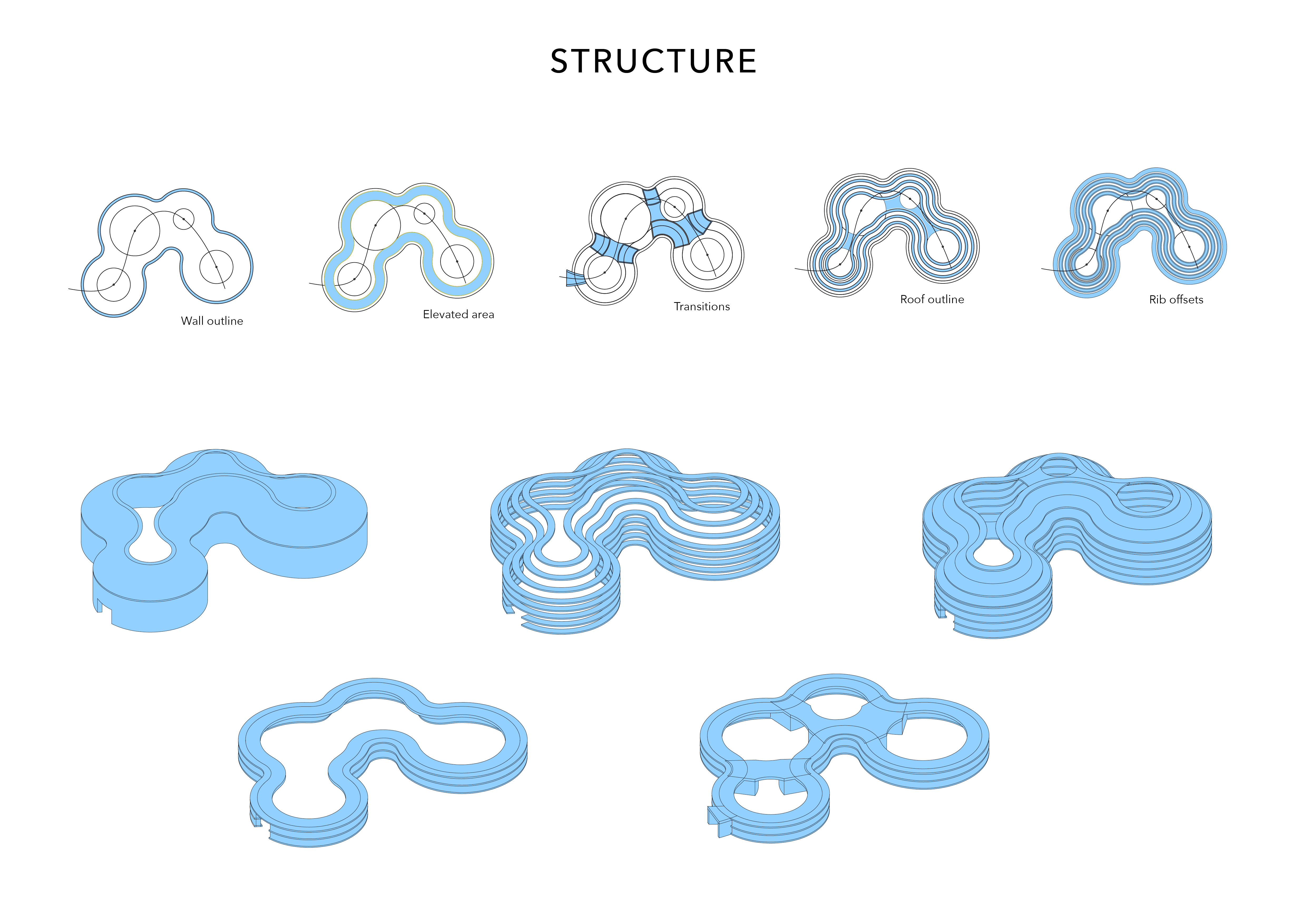
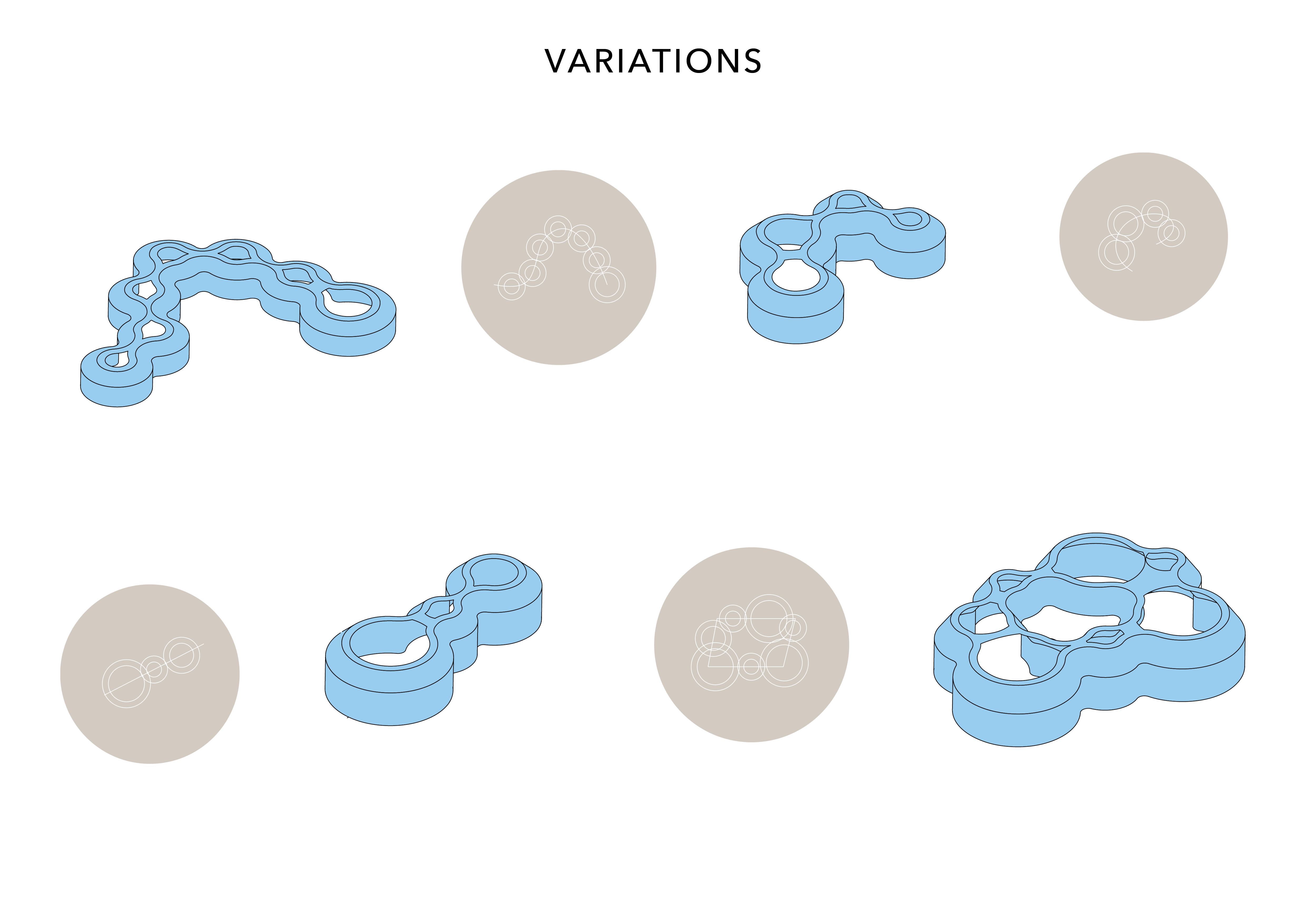
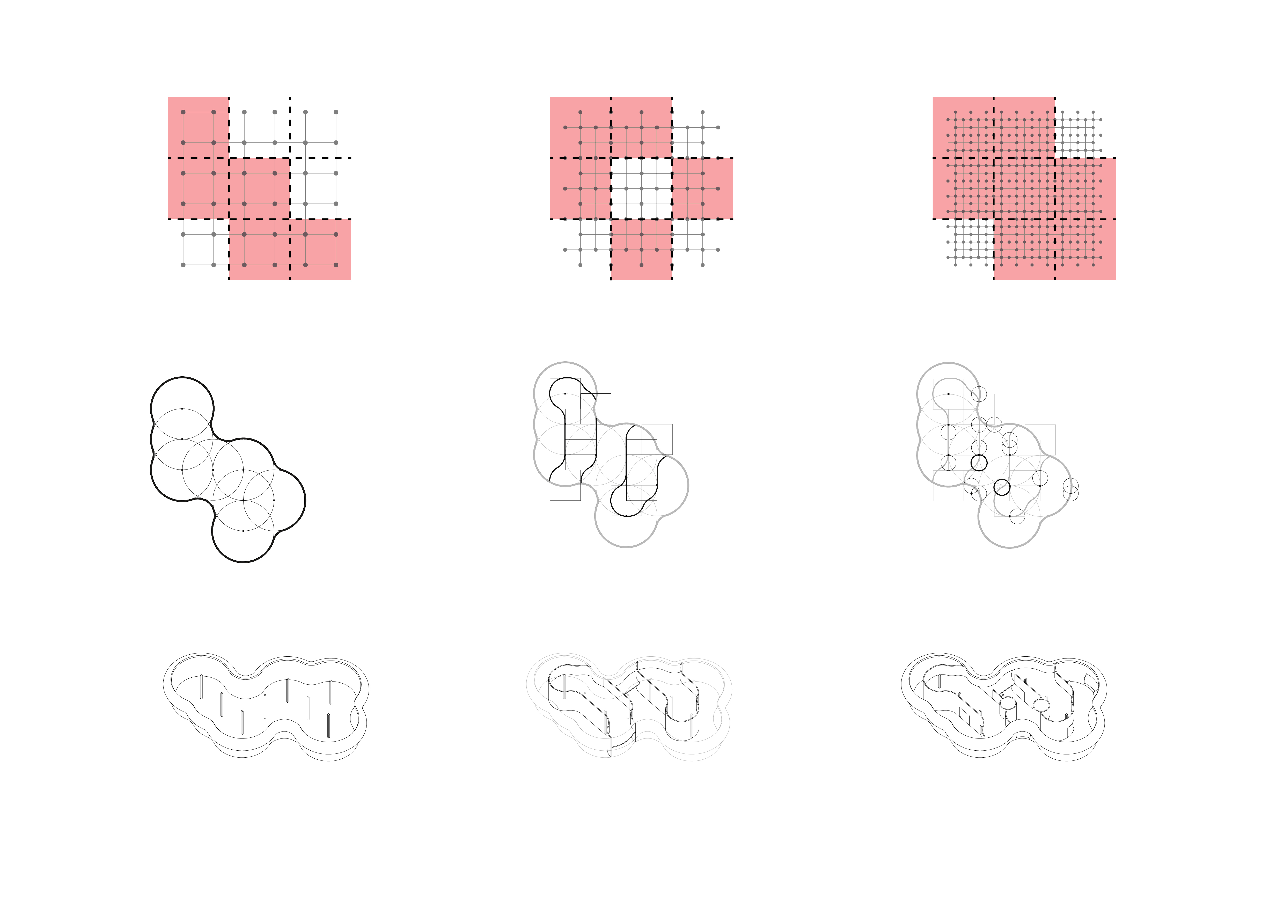
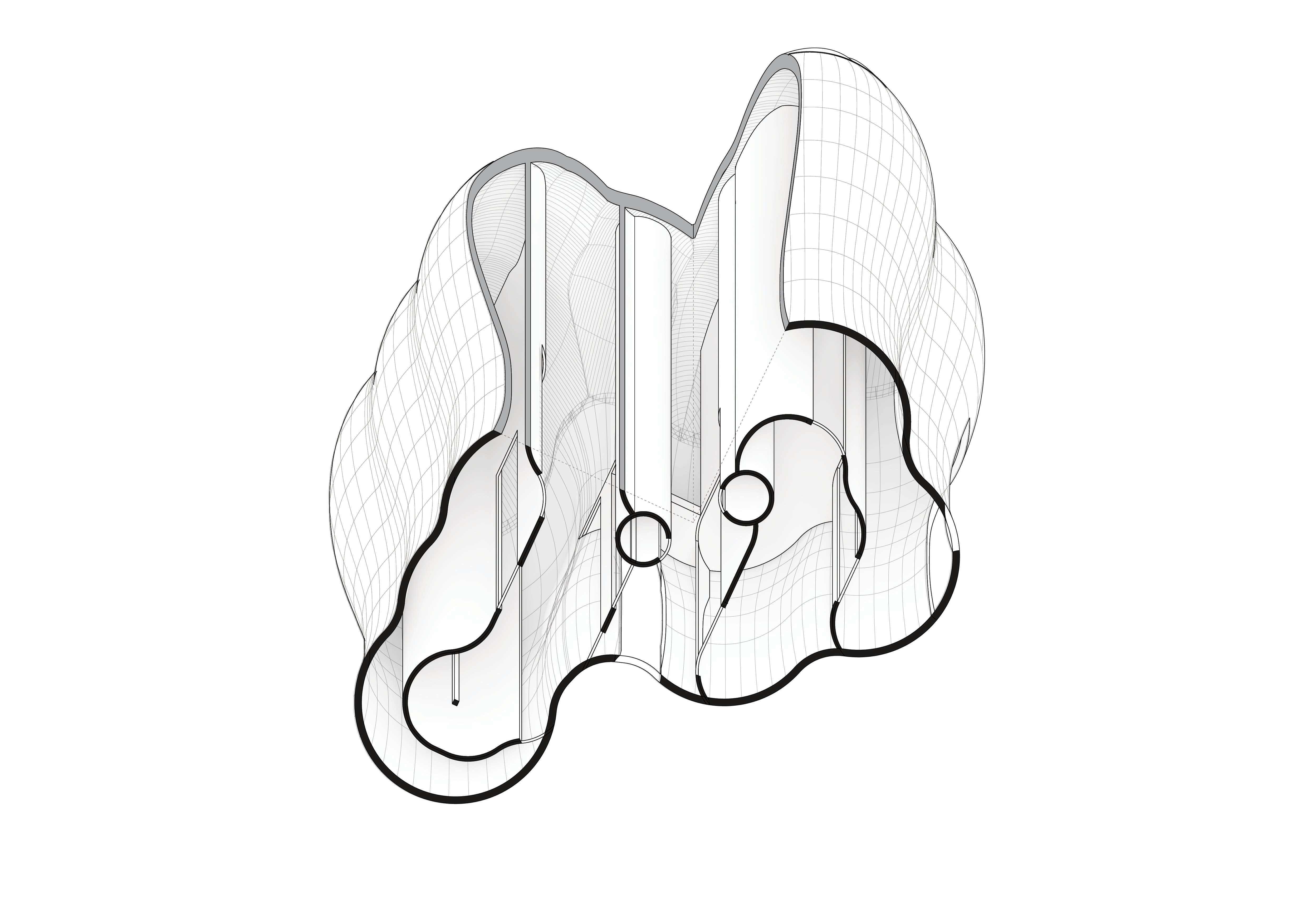
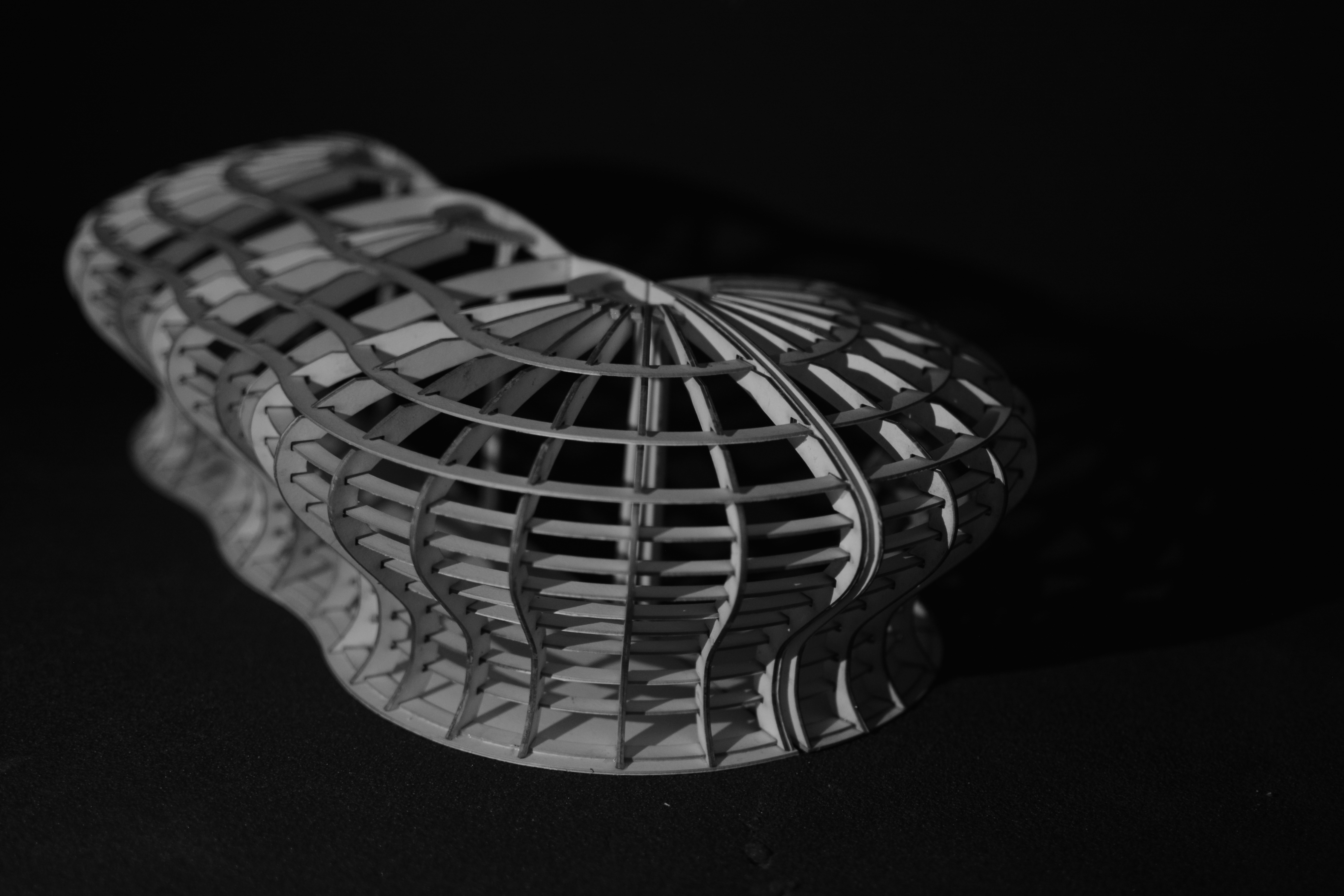
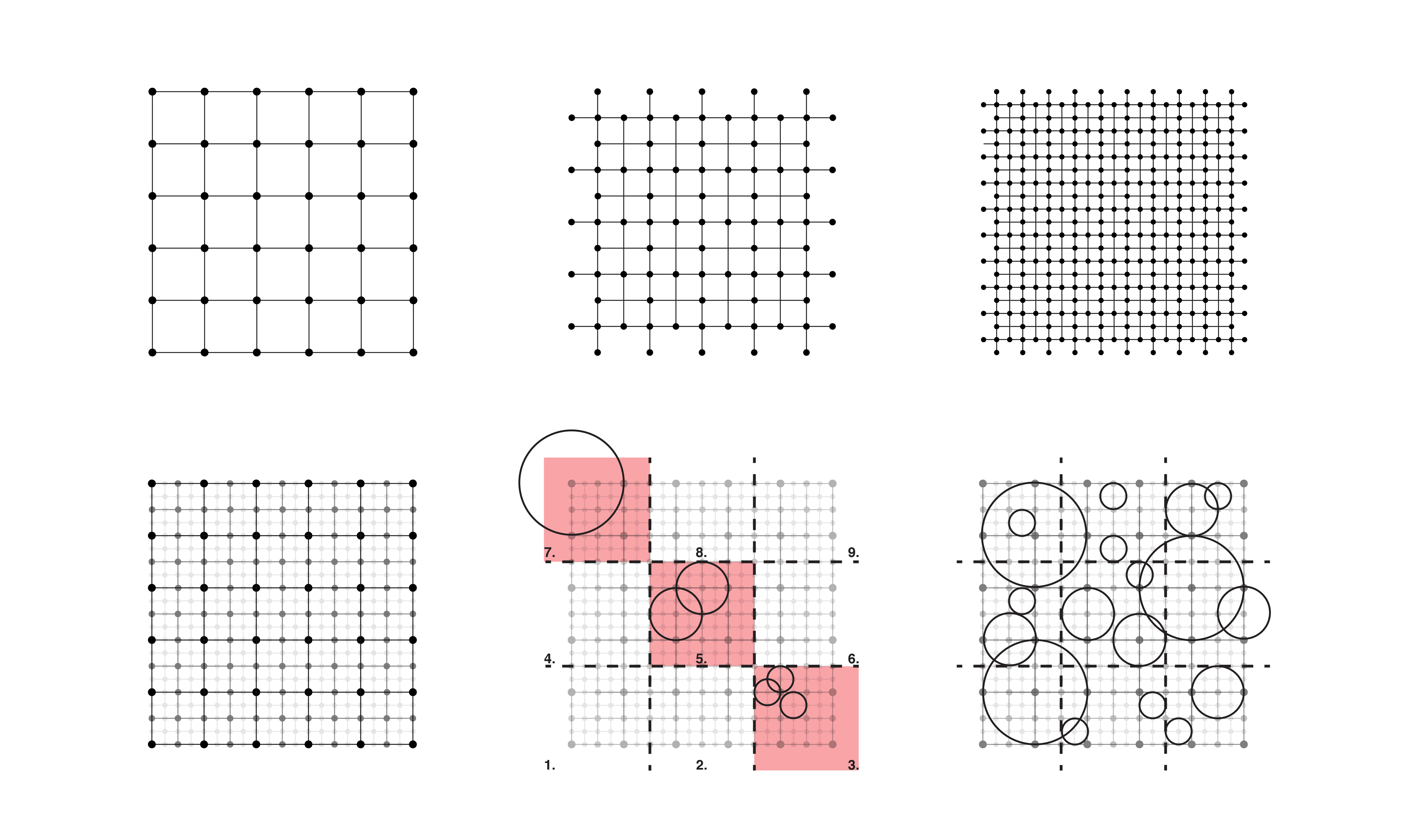
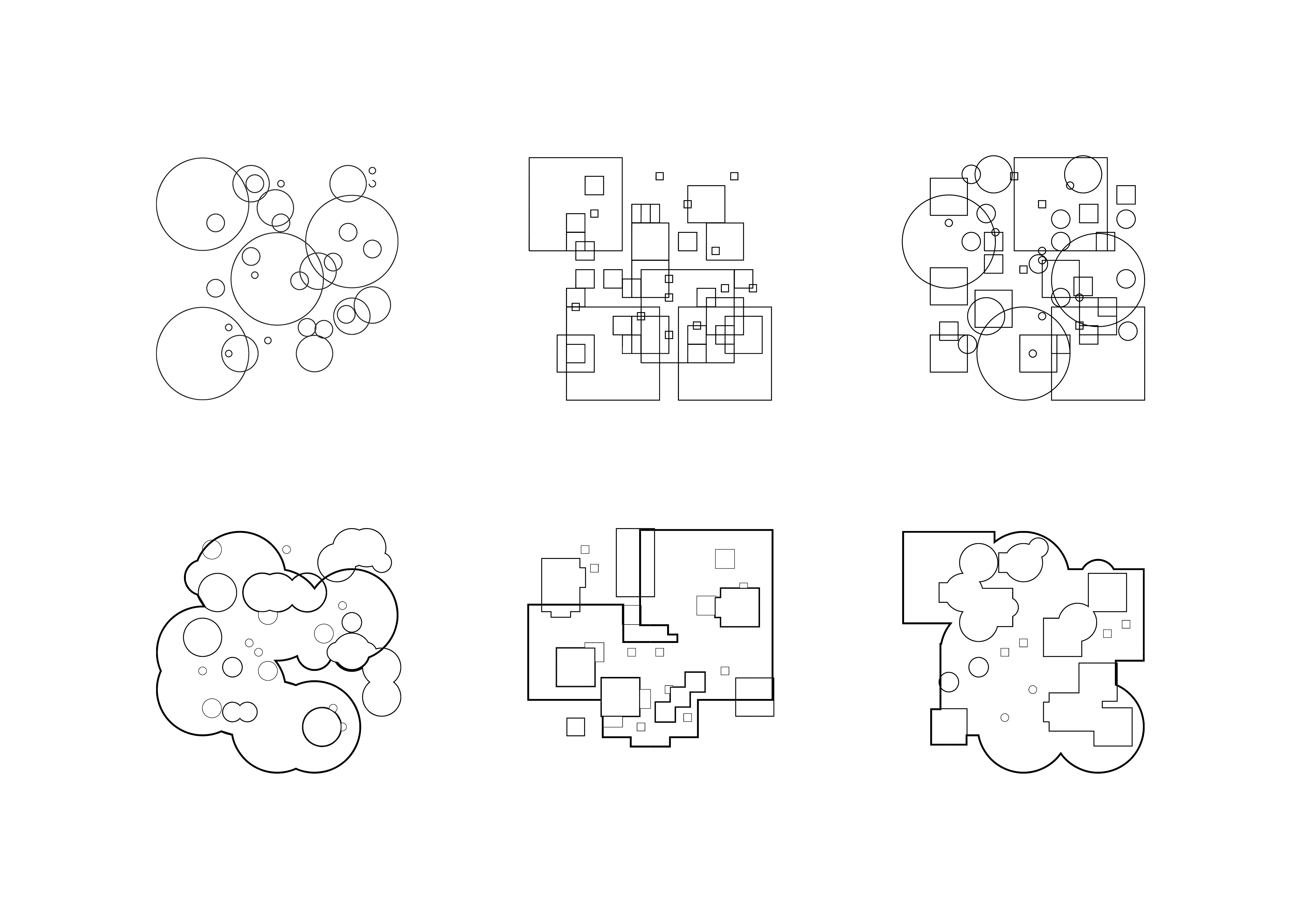
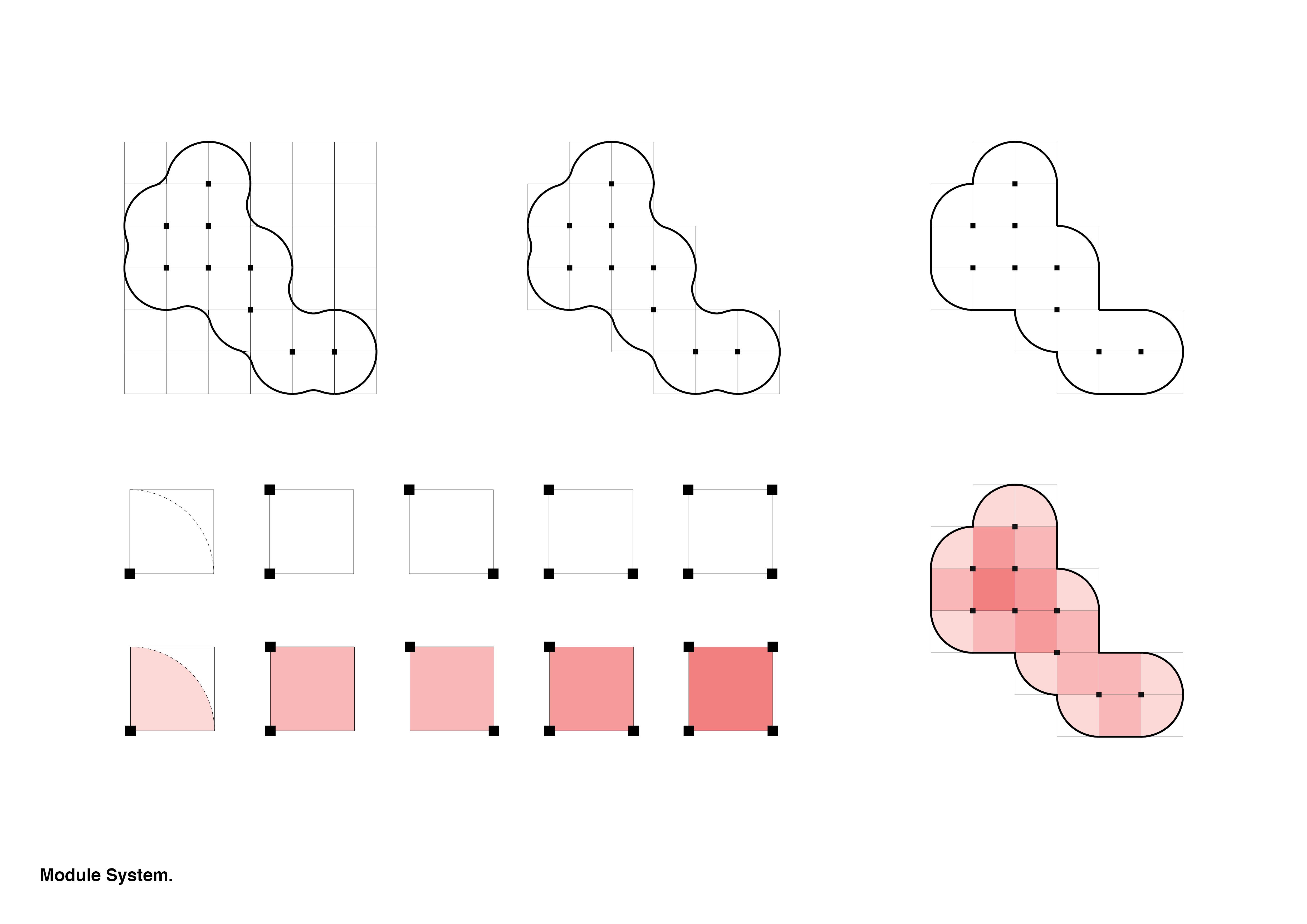
When modelling the structure I found the column intersection could be used as a basepoint to generate both the interior and the exterior framework for the gallery. By referring back to my original grid, each section of the building was dictated by the number of columns in a corner of a square. With this information I was able to split the building into 5 modules which could be repeated and orientated in the grid to form any building configuration generated by the code.

Glasspool_Jack_Project02_FinalBoards4Glasspool_Jack_Project02_FinalBoards7Glasspool_Jack_Project02_FinalBoards8

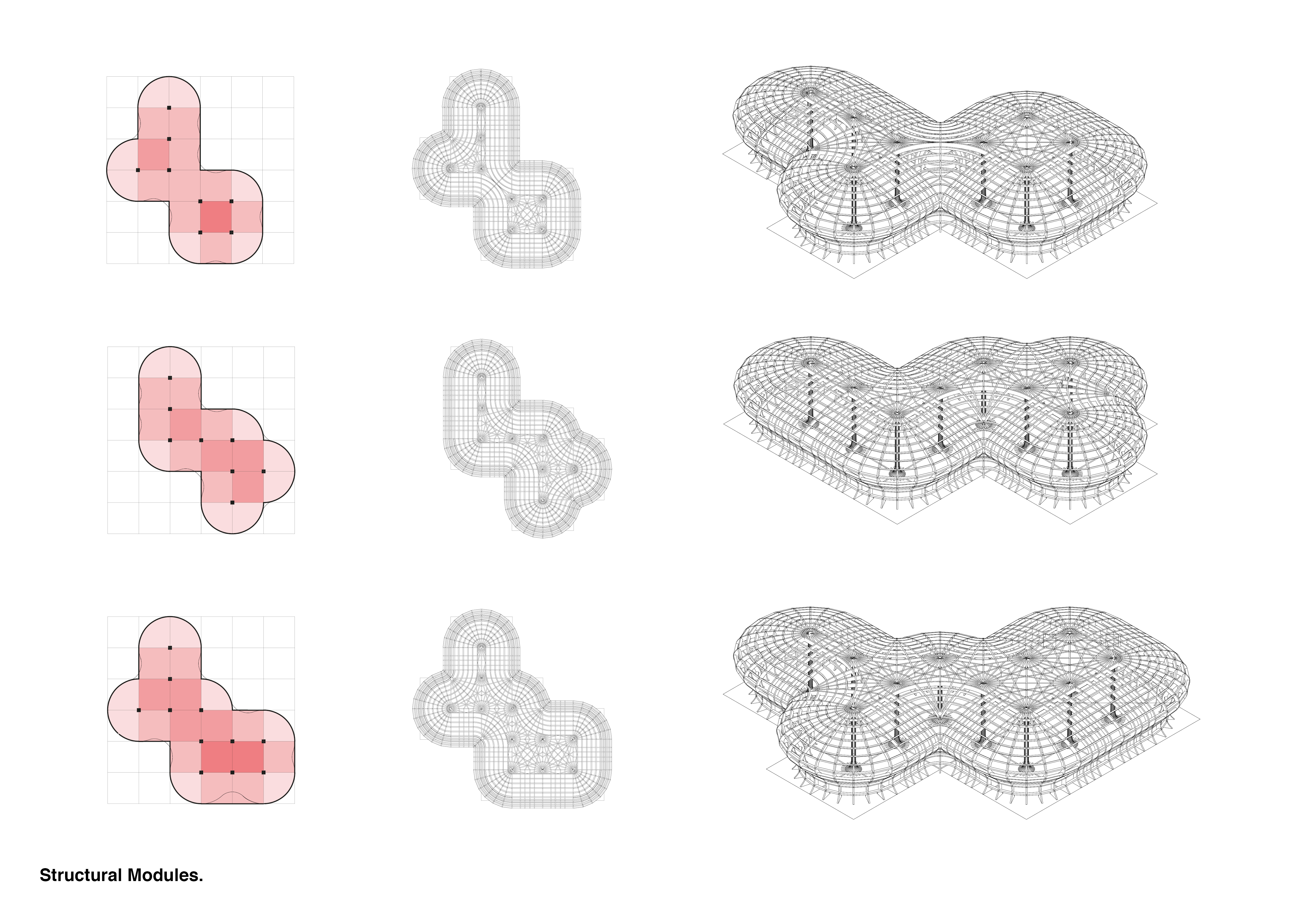
Using the 3 types of sectional modules listed previously, the individual columns could be adapted on a secondary level. With the new structural modules remaining consistent, the interior spaces can be generated by varying the type of supports that span form the columns, using different modular sections to suit separate spaces. This system can be used to combine the exterior, interior, and structure of the generated building.

Glasspool_Jack_Project02_FinalBoards5

Glasspool_Jack_Project02_FinalBoards6

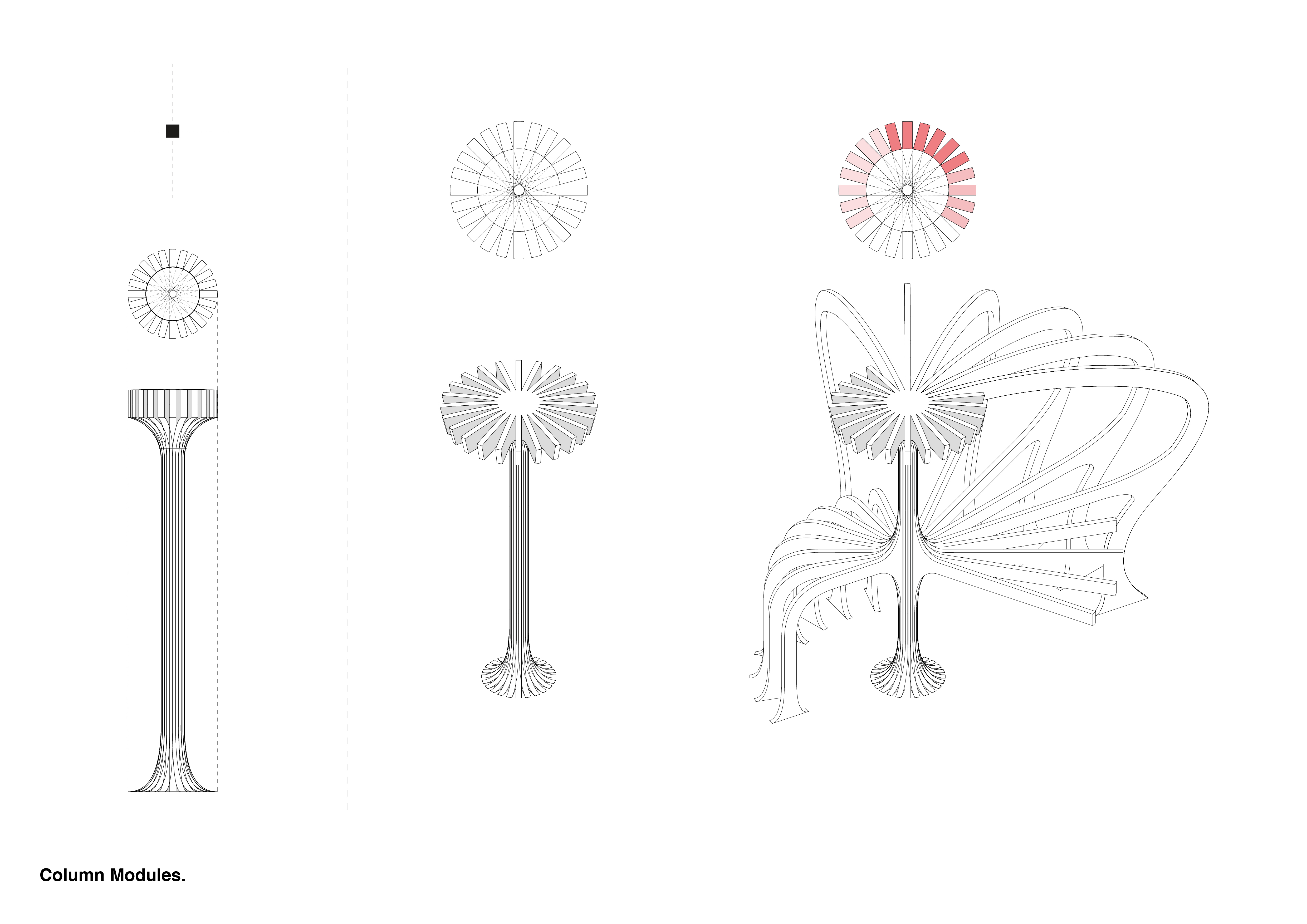
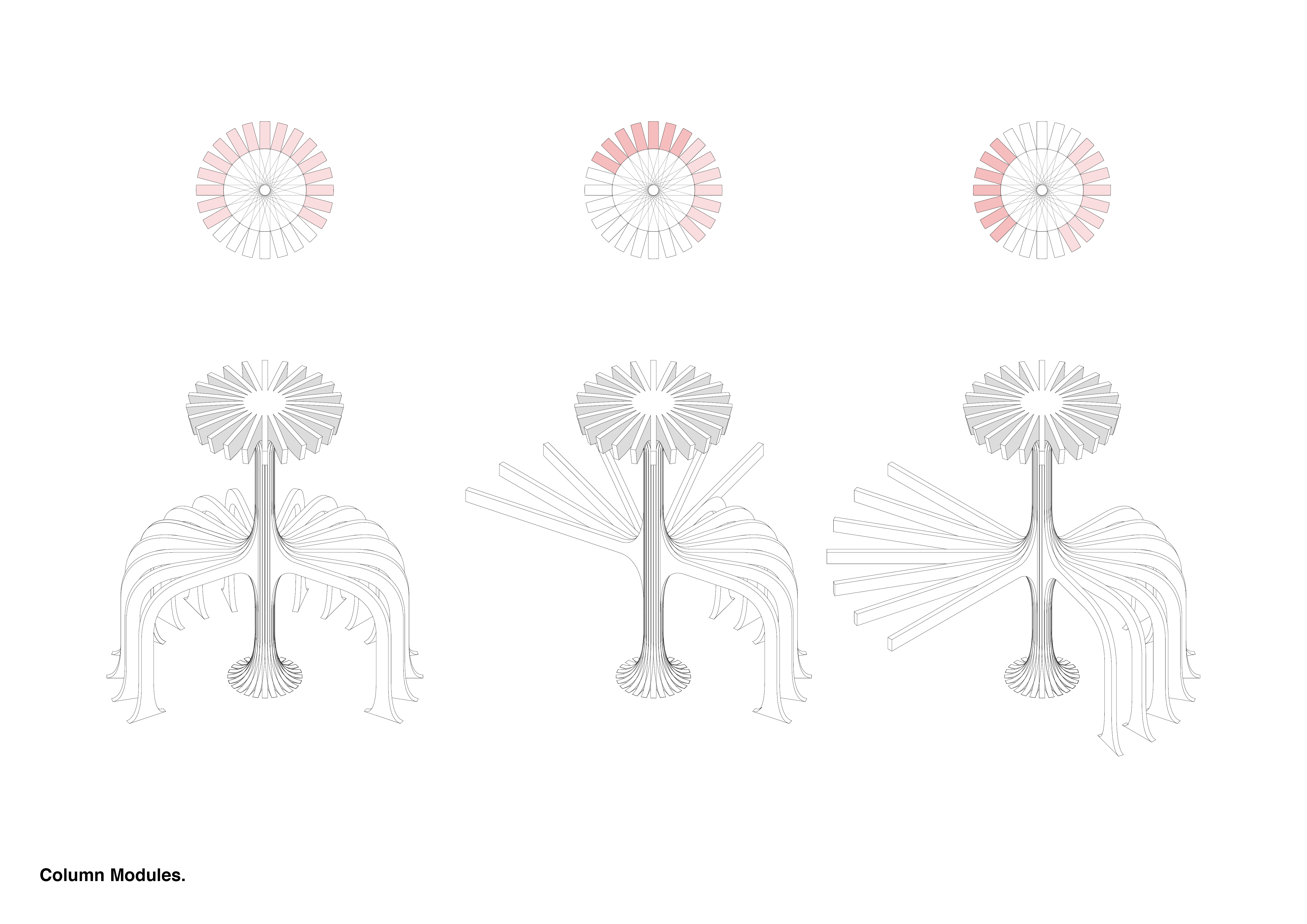
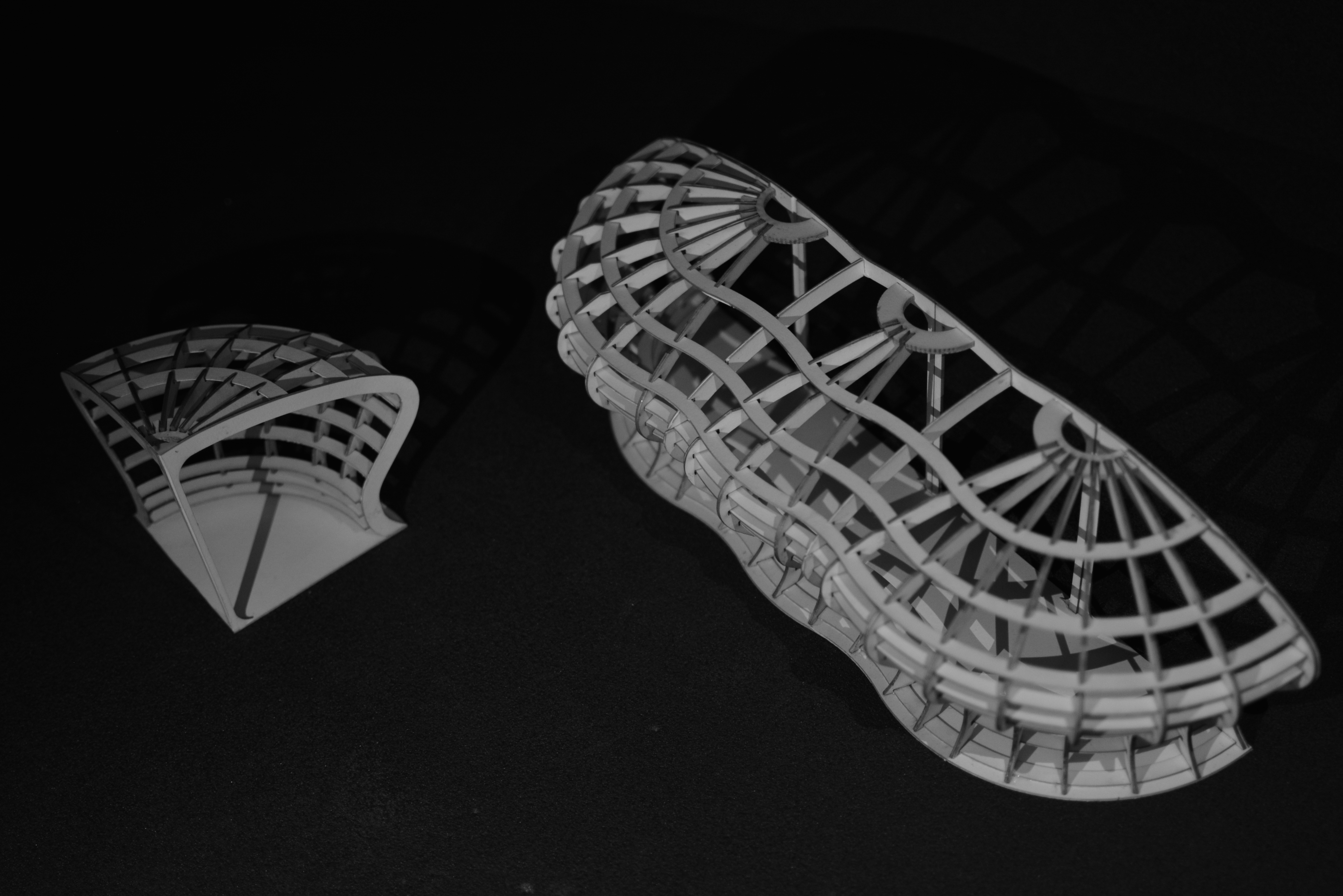
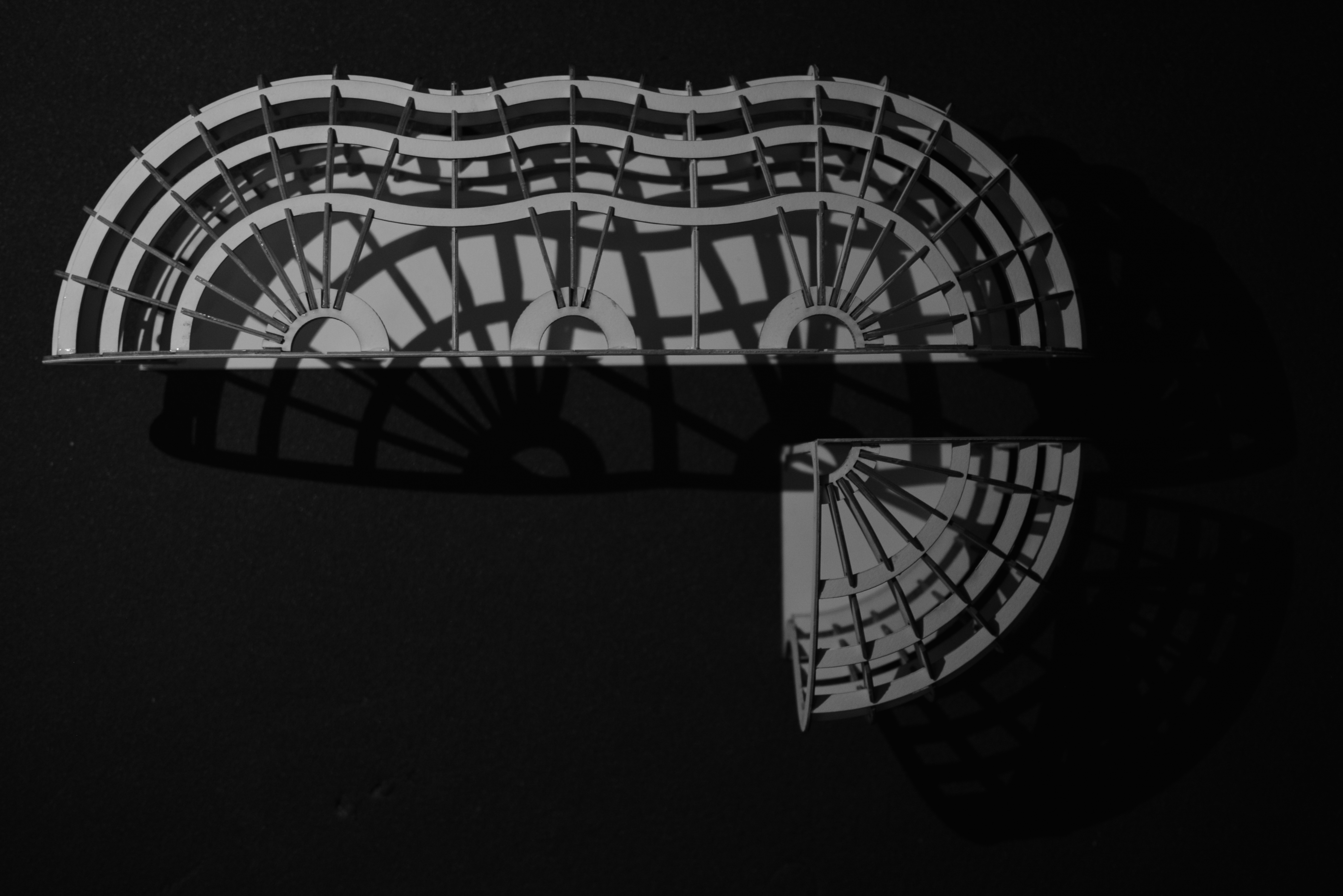
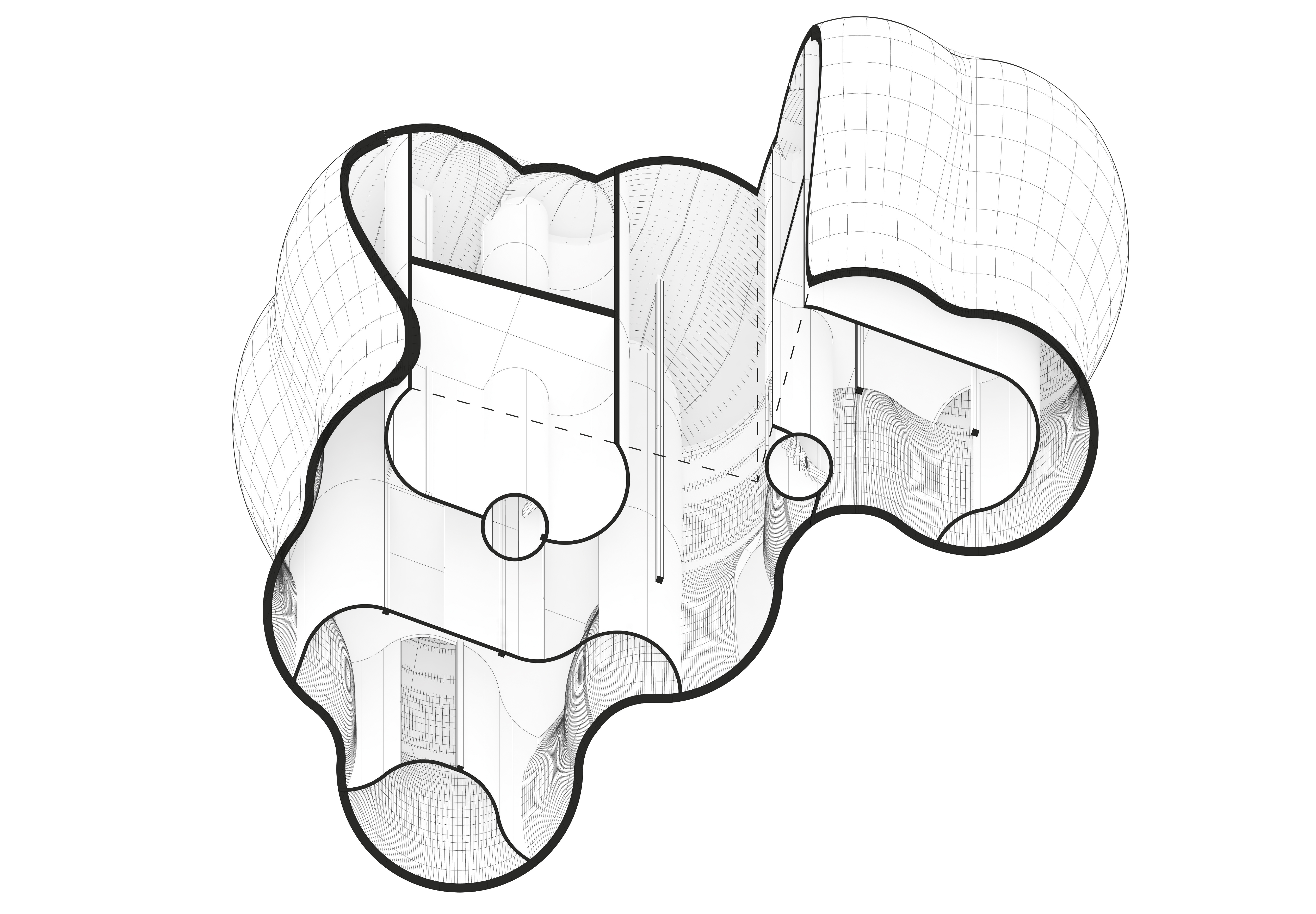
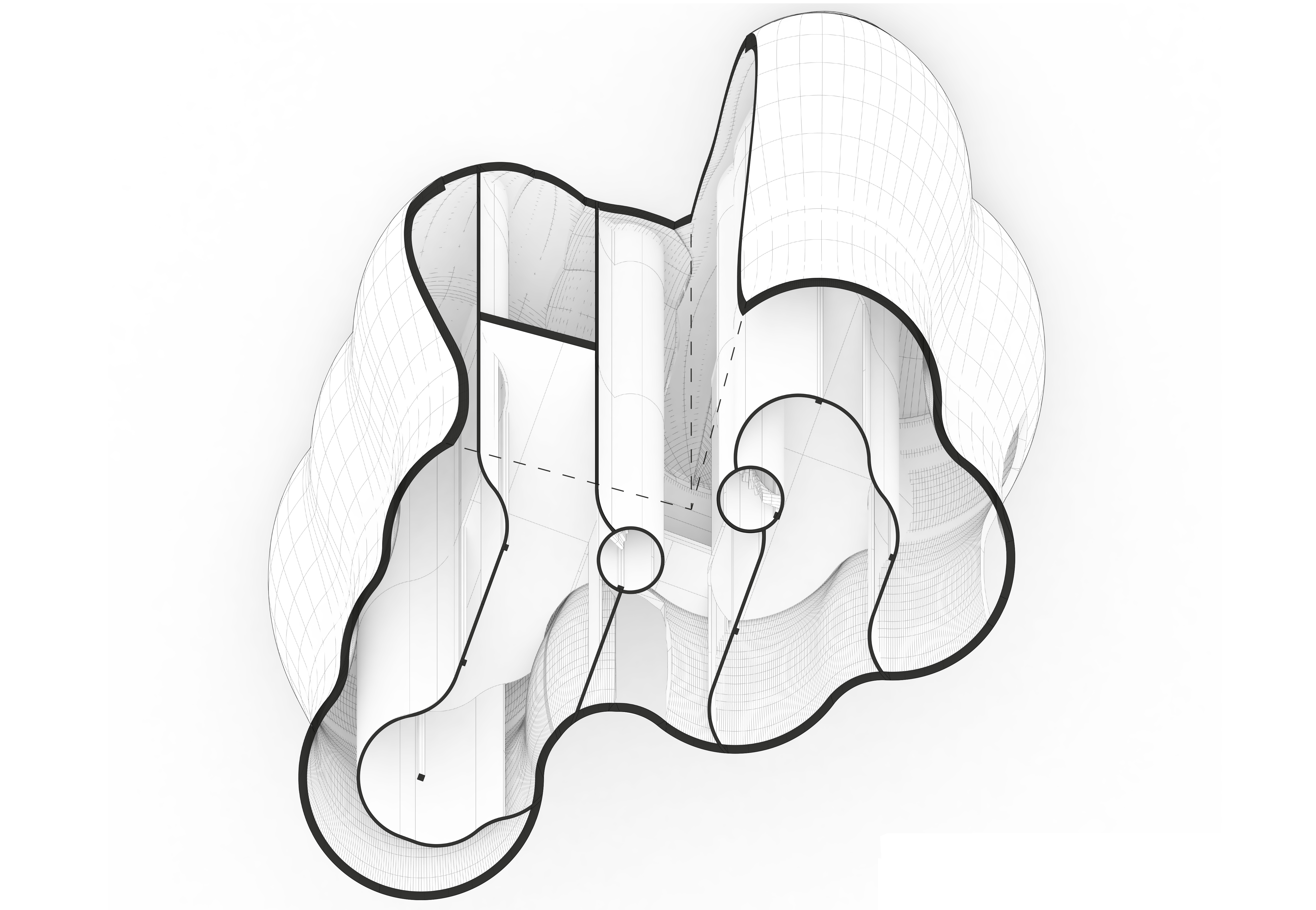
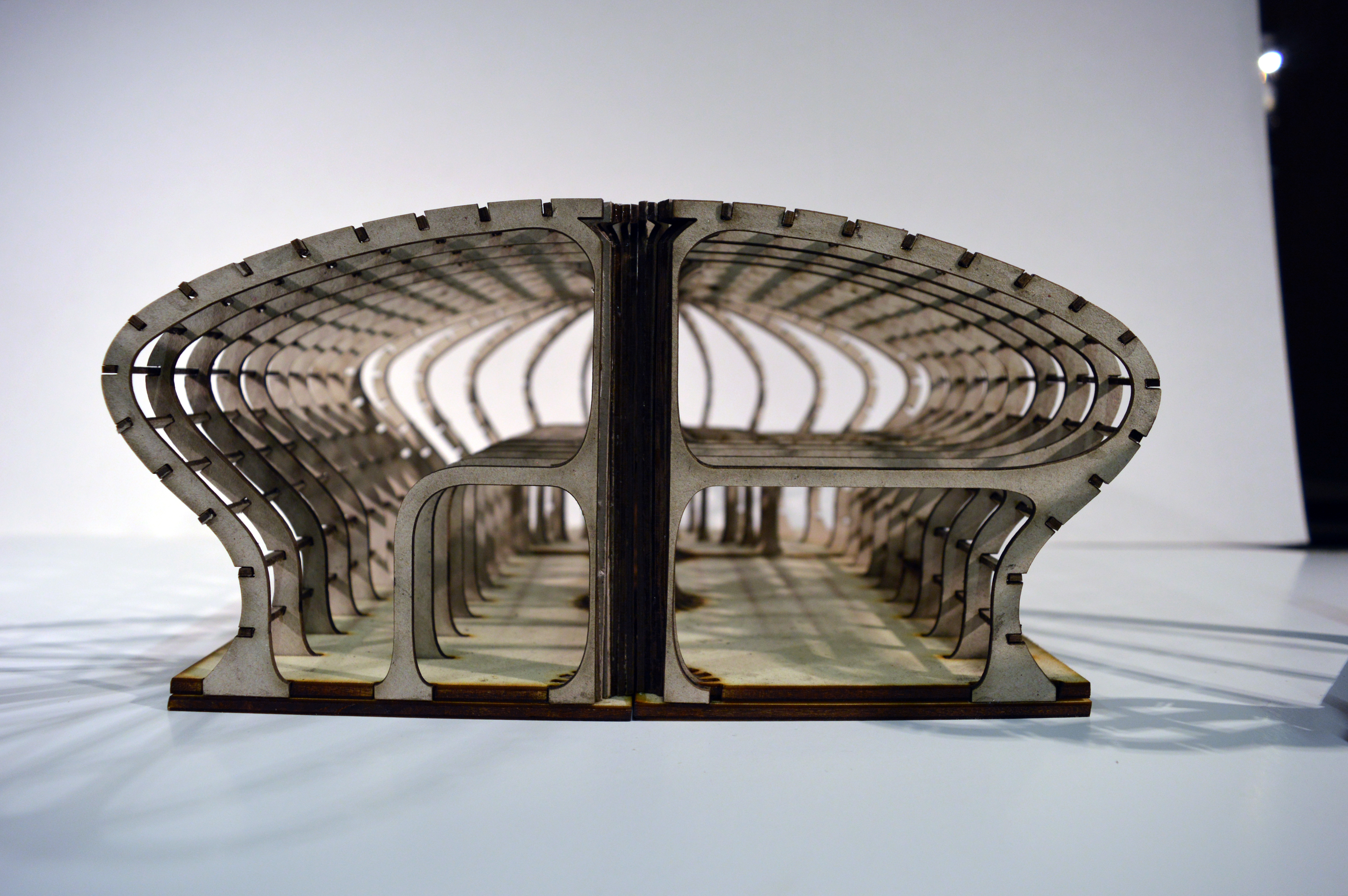
Undulating roof & column intersections:

DSC_0438

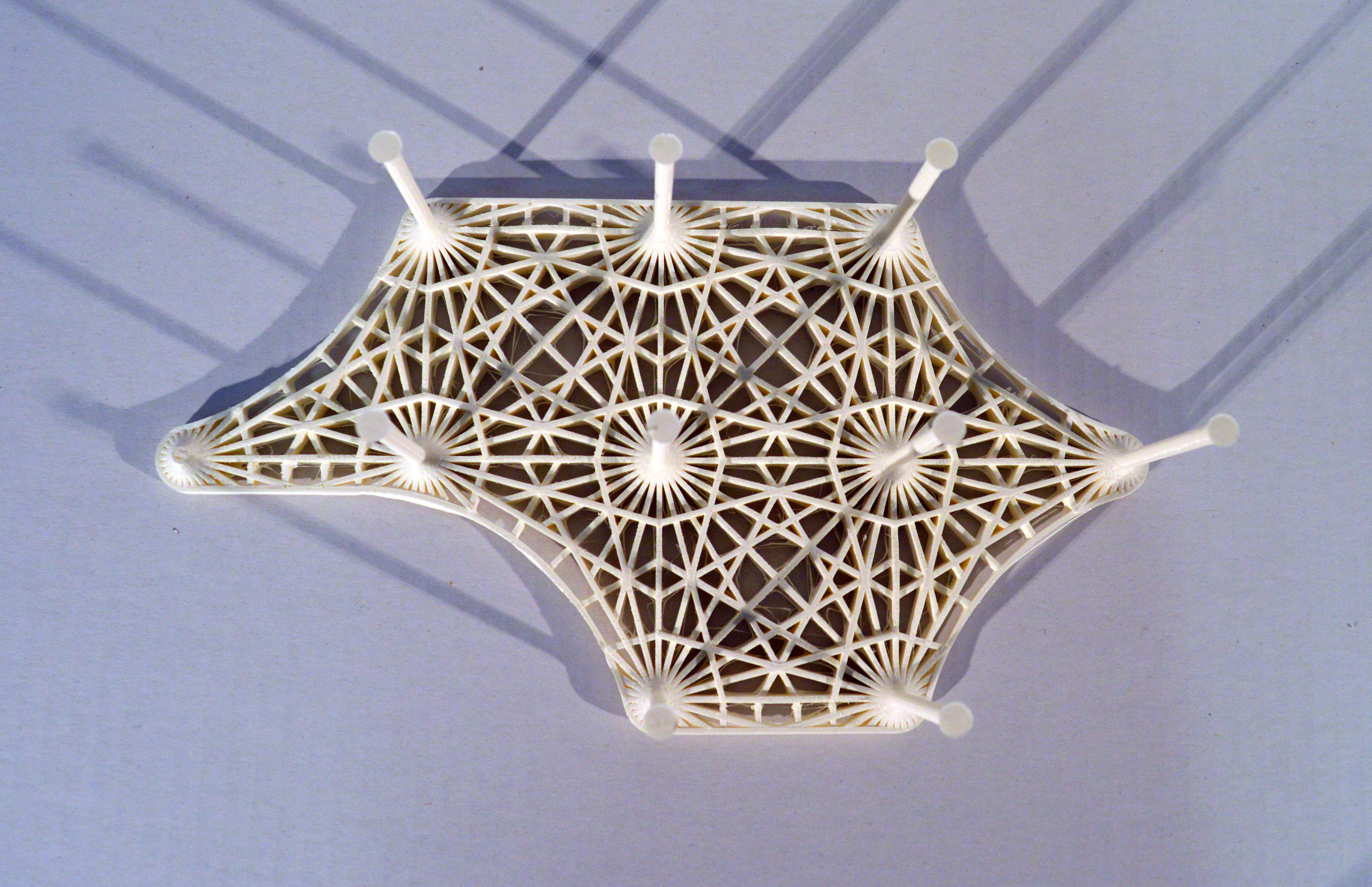
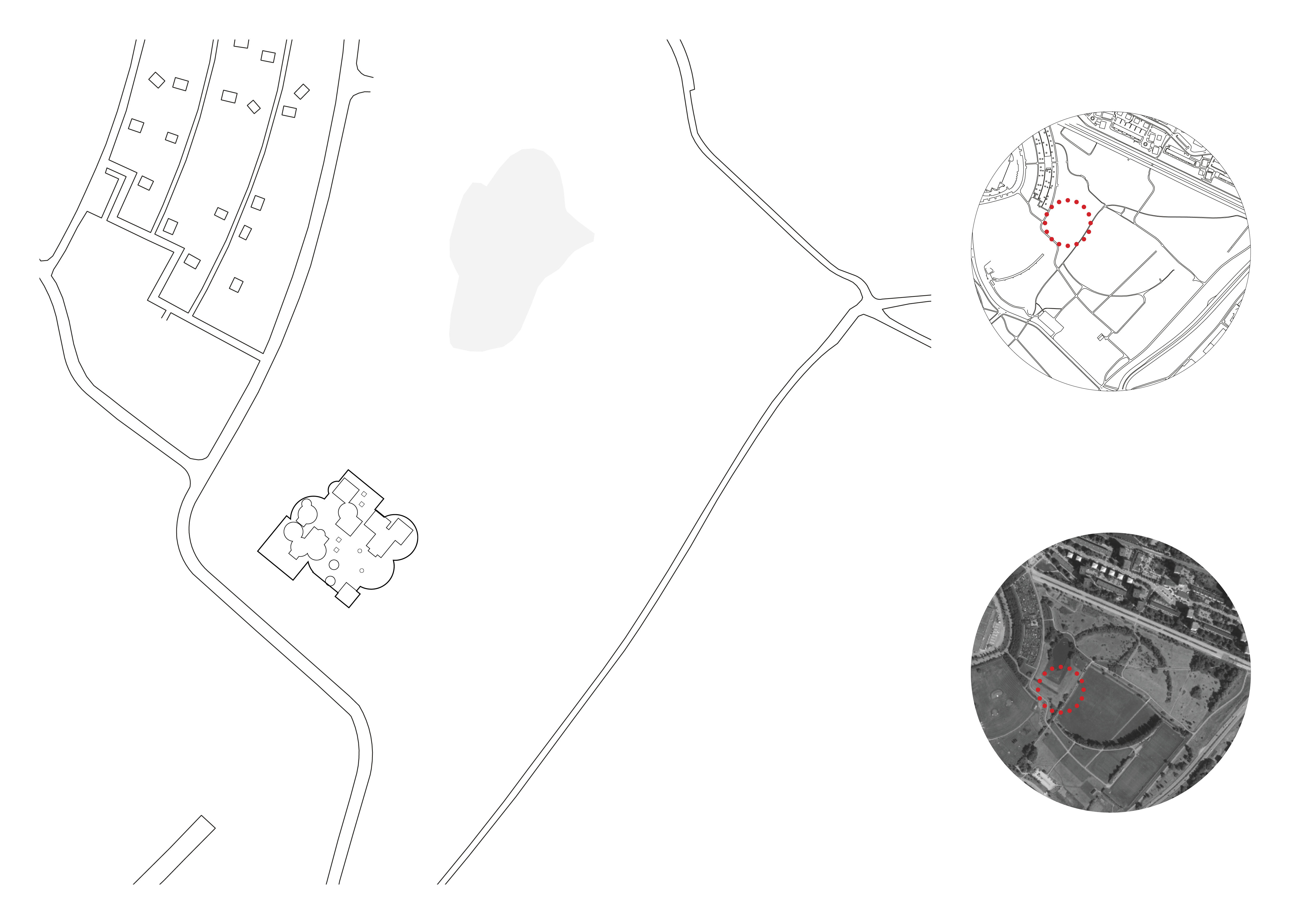
Combining these systems together I was able to create an example structure for housing the art gallery:

Glasspool_Jack_Project02_FinalBoards92Glasspool_Jack_Project02_FinalBoards9


28 grids later.

Previously I began to develop how my grid system would work in a 3-dimensional form. Offsetting the building boundary as it is extruded vertically, I experimented with different curve patterns to see how the external form could be generated.

A

Combining this with my 2-dimensional coding system, I generated an example layout. This created an initial layout in plan and section, along with an axonometric view of the roof, allowing me to begin to see how the interior spaces could develop.

B

B2

B3

To explore how this form could work tectonically, I built a structural model of the exterior boundary. Using this I hope to explore further how this layer can interact with the internal spaces for the gallery.

DSC_0638DSC_0644DSC_0655DSC_0662

27 grids later.

Continuing with my experimentation of grids, I have been developing a more complex system which can be used to generate spatial arrangements that respond to specific site conditions and parameters.

Exercise 3 Sheets-4

I have split the building into a primary, secondary, and tertiary layer, each produced through an individual grid which generates different sized shapes.  The 3 overlapping grids are each sub-divided into 9 regions, which can be programmed to determine the probability of a shape being generated in a specific region.

This system means that I can use certain site conditions such as views, orientation & access to instruct the building form.

Exercise 3. Jack Glasspool-6

To convert this into a 3D form, I continued to use the layers generated through the 2D grid. For the primary layer I combined the large shapes to produce an exterior boundary. Extruding this vertically, I offset the boundary at regular intervals and lofted these together to produce a more irregular form. Repeating this with the second layer, I was able to produce interior walls within this boundary, with the final layer used to generate initial circulation openings.

Experimenting with this process on site, I have generated two varying buildings on site which have both been designed using the same parameters.

Example 1:

Exercise 3 Sheets-6

Axonometric View:

Exercise 3. Jack Glasspool-10

Example 2:

Exercise 3 Sheets-7

Axonometric View:

Exercise 3. Jack Glasspool-9

intersections & overlaps.

Looking at spatial configurations of existing plans, I found layouts interesting that had more unconventional circulation patterns. In particular the spaces that were formed through the resulting overlaps or intersections.

Exercise 2 - Blog.jpg

I began by looking at the spaces created when horizontal and vertical walls were randomly arranged in a uniform grid. Developing this further I introduced a wider variety of rotations and intersections to see how this would impact the spaces in-between.

Exercise 2 - Blog2

In an attempt to escape the rectangular boundary I experimented with sequences of squares and circles in different sized grids, creating spaces from the overlapping boundaries. By merging these varying scaled shapes as if they were layered, I was able to begin to create a more hierarchical spatial pattern.

Exercise 2 - Blog3

Additionally, I began looking at how one of these patterns could be placed on a site, and will explore further how aspects of the site could be implemented as parameters for my future code.

Exercise 2 - Blog4