ii. big data and nomadic robotics.

Studio 9_Project 3_Task 2: Occupations and Interventions.

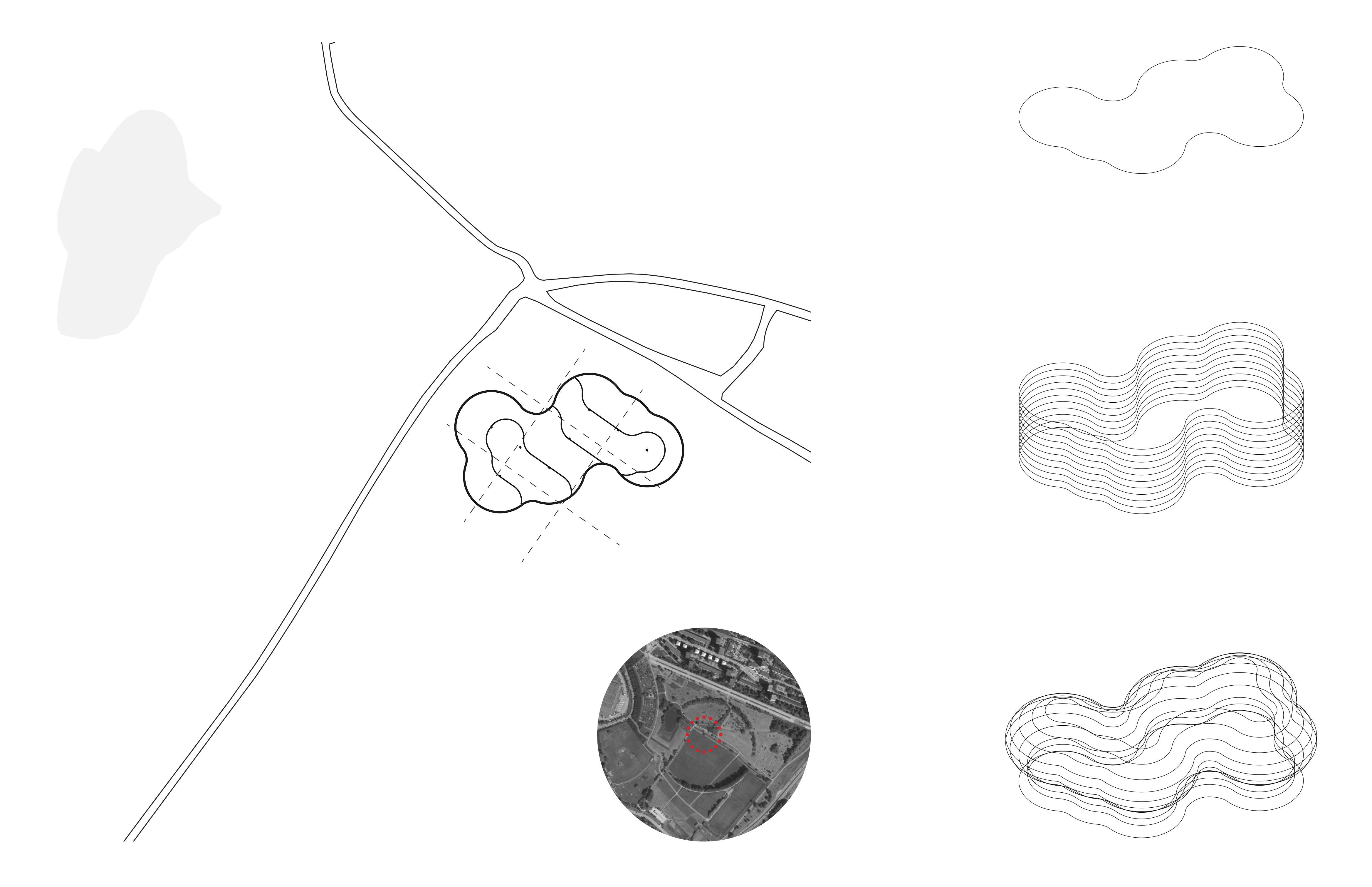
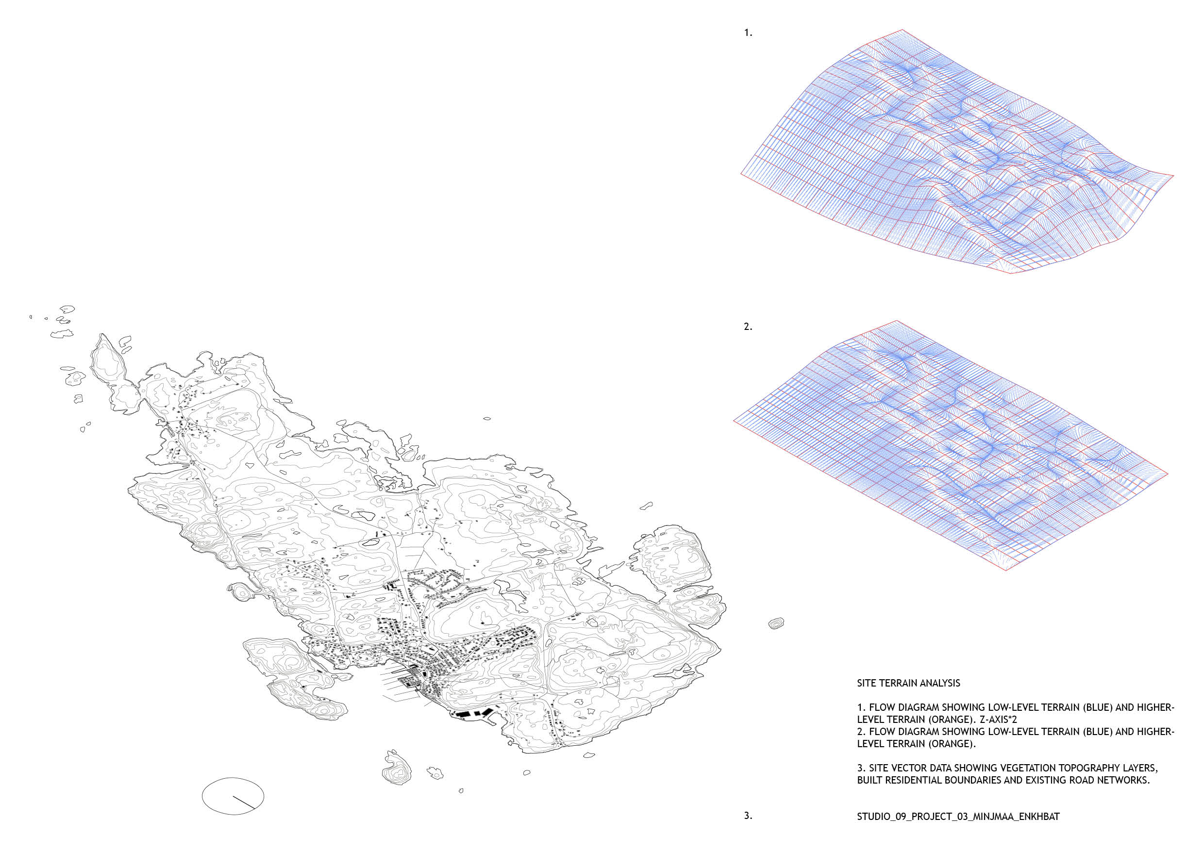
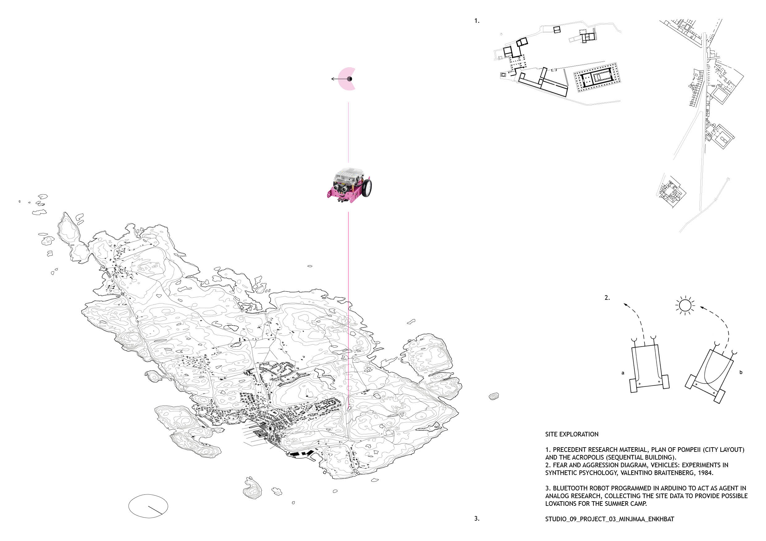
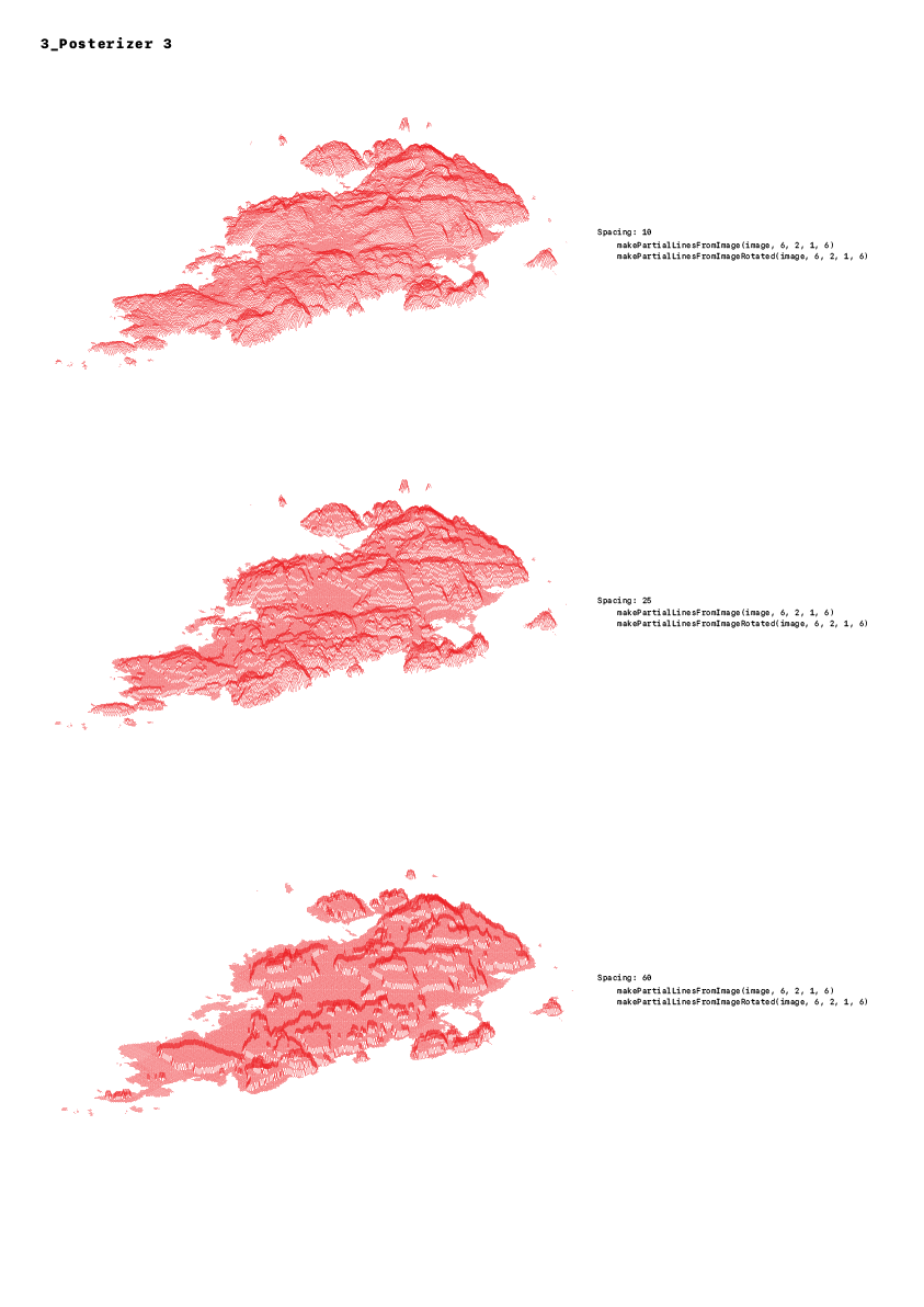
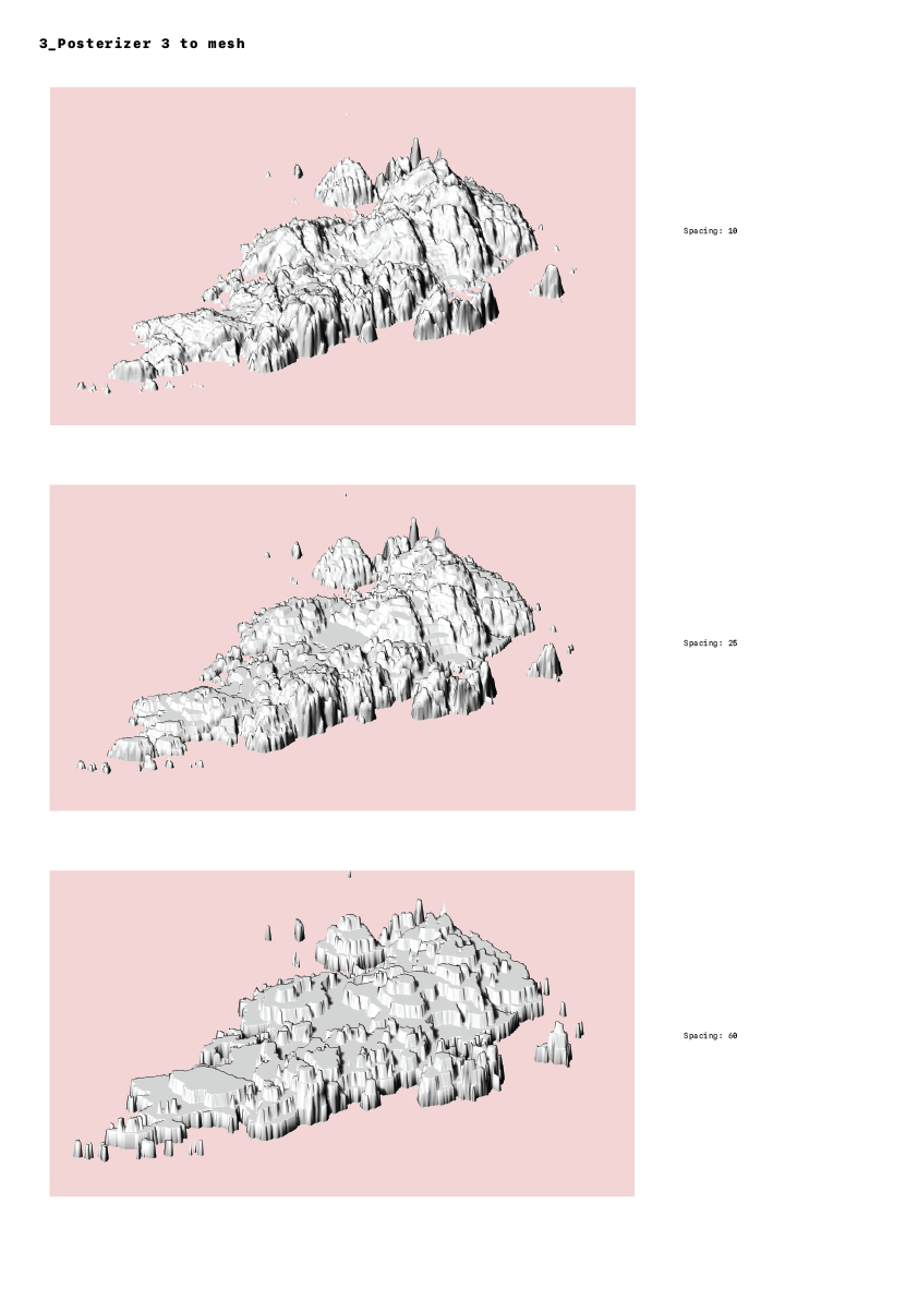
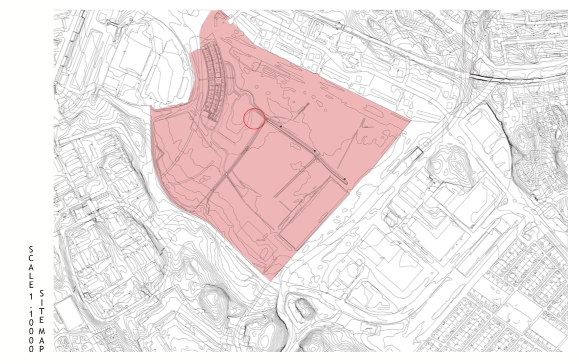
To occupy the site I began by collecting and analysing site data for Malmön. The program QGIS for editing and analysing geospatial information was used to extract the vector information; topography, population and marine geology. A colour png map provided the basis for extracting the 3D terrain data using a python script and into Rhino, with initial topography analysis through flow diagrams in grasshopper. A photographic study was also carried out and compiled into a booklet.

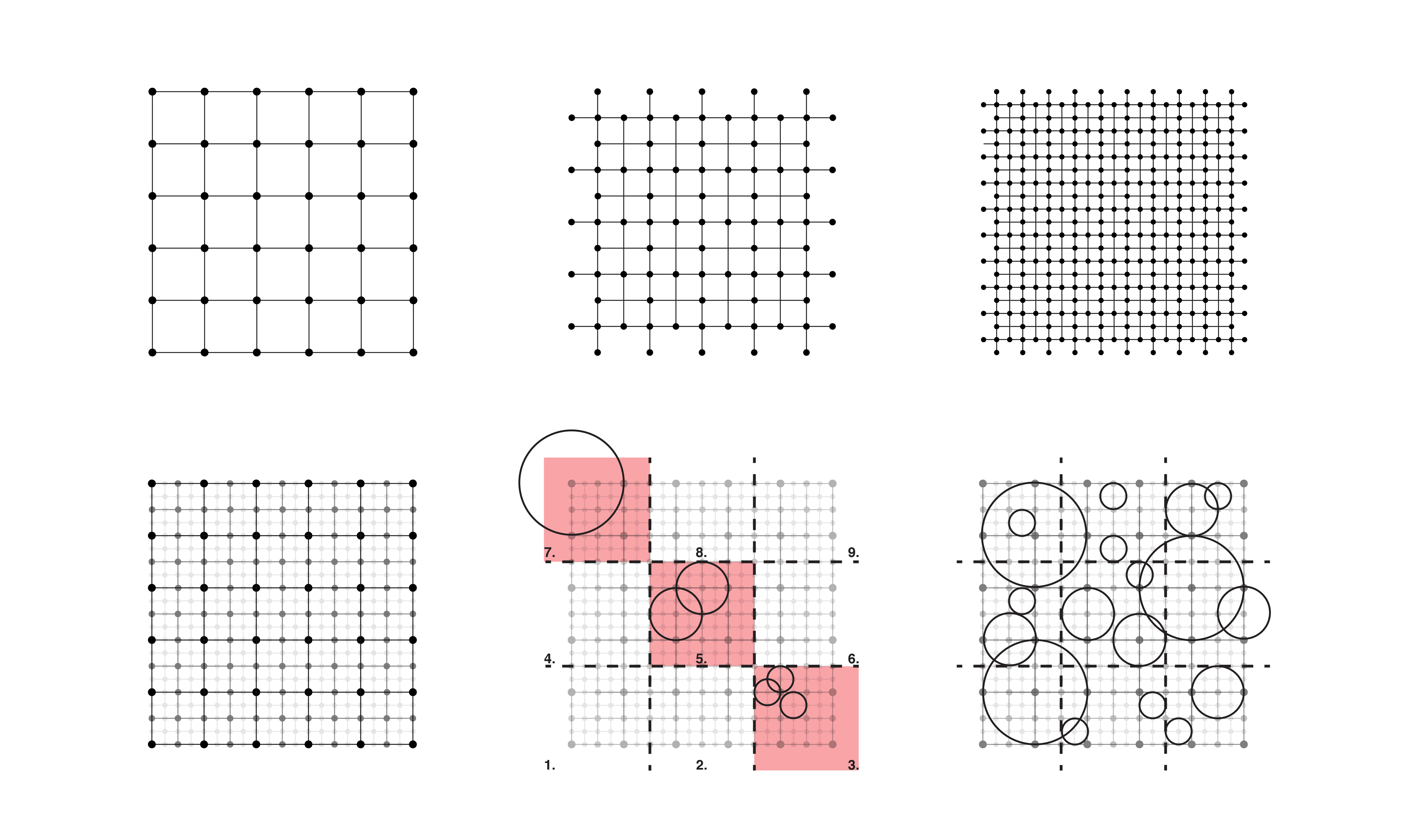
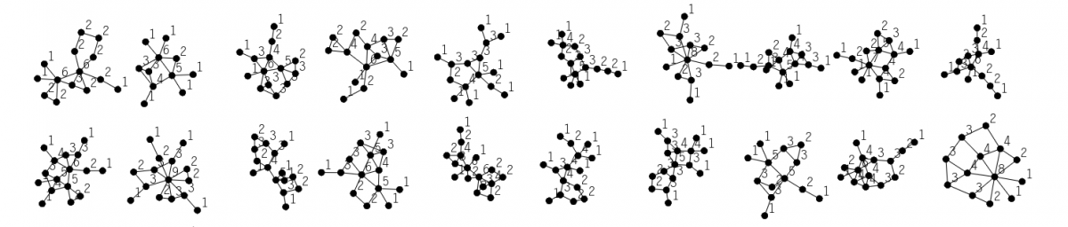
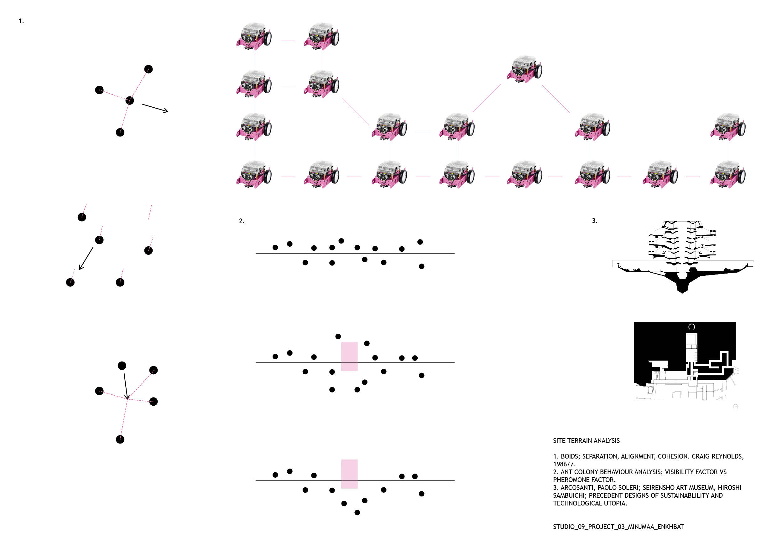
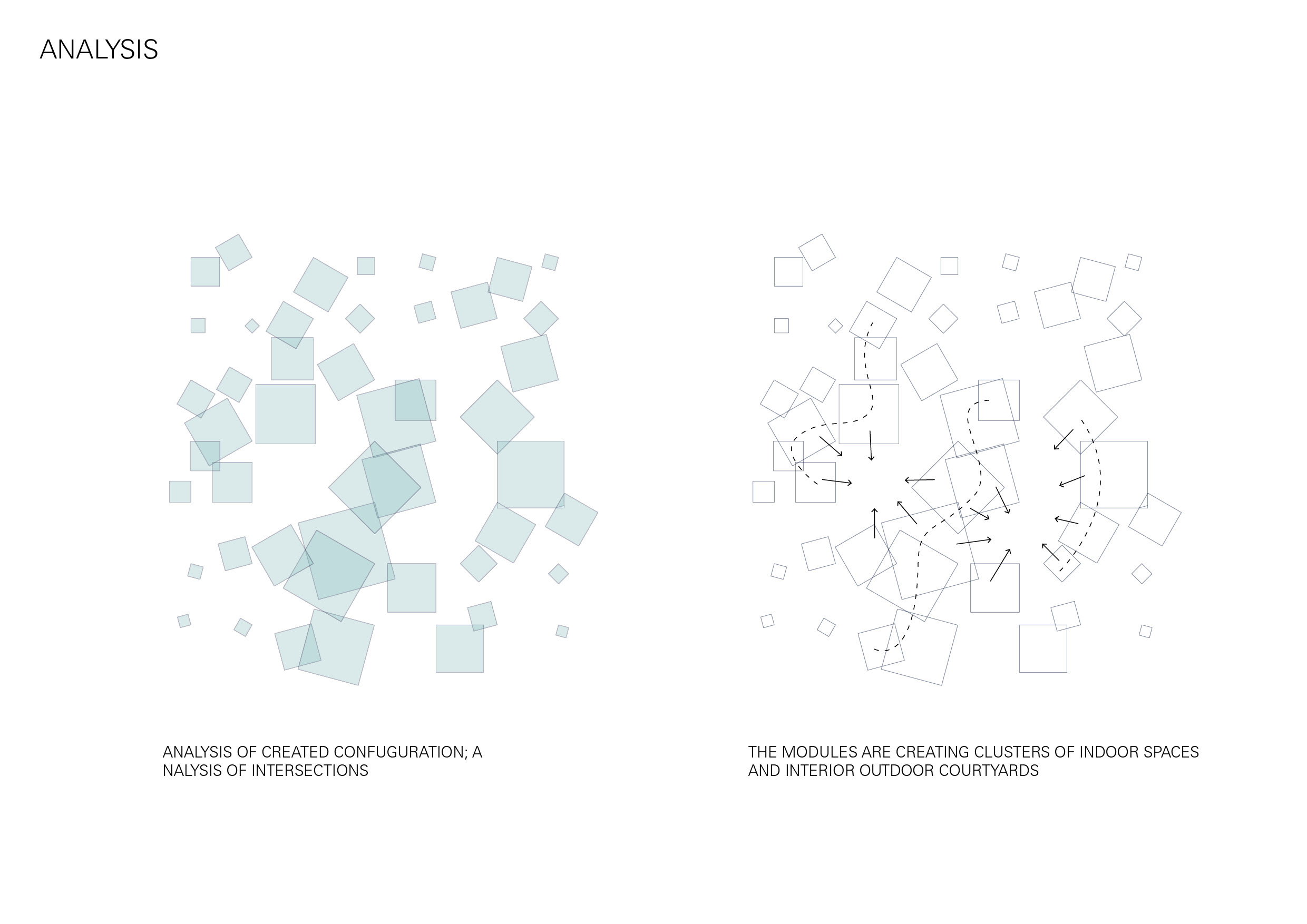
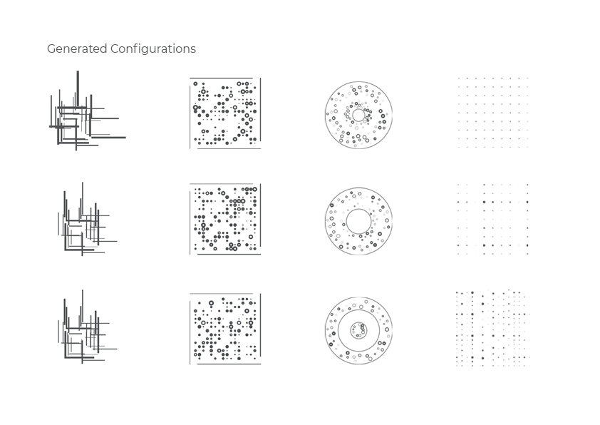
The intervention aspect was based heavily on ABM research – agent based models. An agent is aware of its surroundings and its abilities. When acting in a collective manner they exhibit swarm intelligence, the collective behaviour of decentralised self-organised systems. This means each member autonomously offers its abilities in order to study an overall system. The members, or agents, self-coordinates without a leader and cooperate in solidarity resulting in a self-healing system. This allows members to be added or removed dynamically as the agents will recalibrate in a constant feedback loop.

‘Boids’ by Craig Reynolds was the grounds for my research into swarms and flocking behaviours for computer simulations. His theory is a basic flocking model consisting of three steering behaviours; separation, alignment and cohesion. Ant colonies that organise using pheromone and visibility factors were also part of the initial studies.

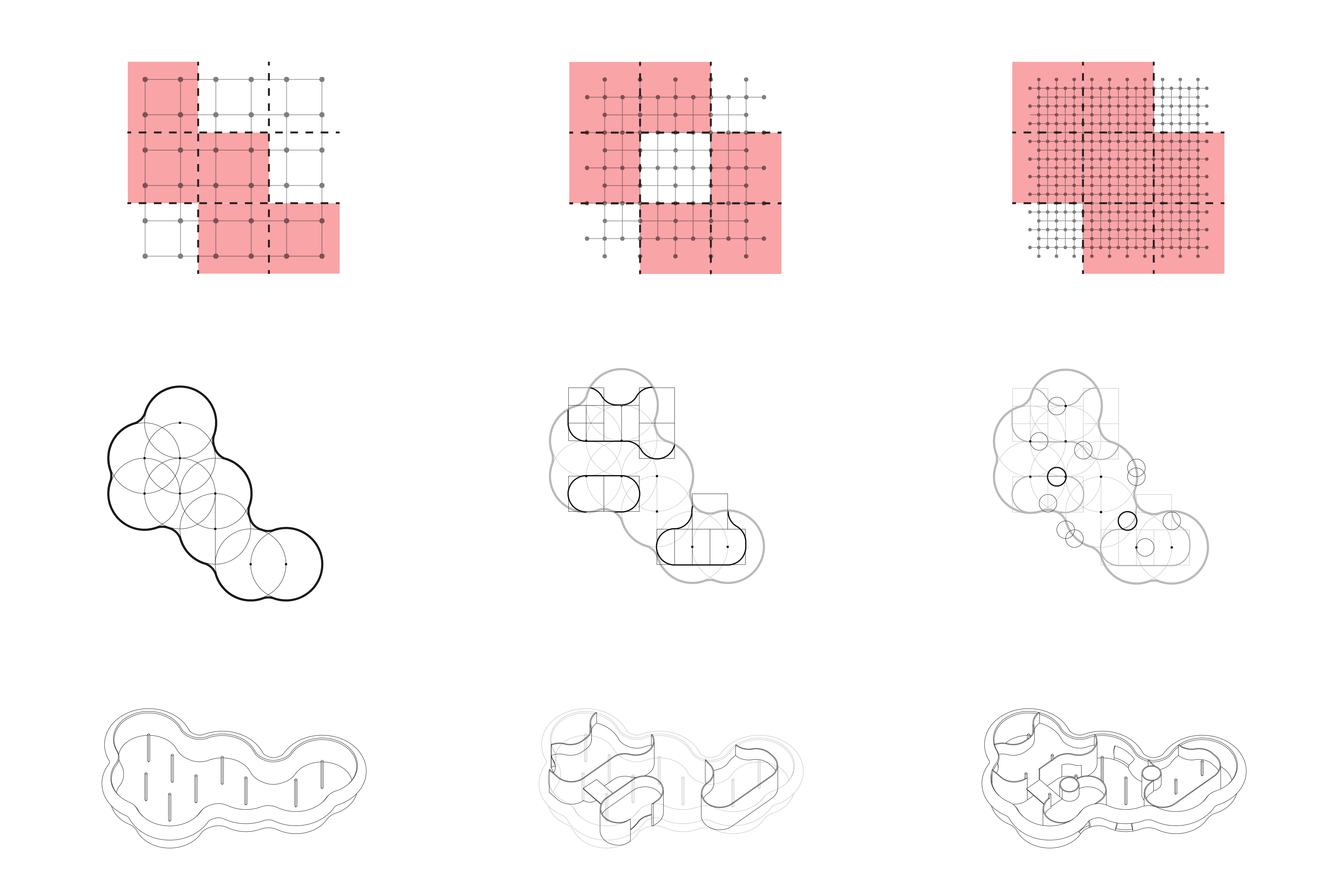
I would like to base project 3 on the collection of site data using agents and subsequently allowing the agents to alter the collected data in order to intervene and implement the summer camp design on Malmön. To engage with this theory in the material dimension, I decided give form to the agent as a mini Arduino robot name Mö. This allows for real-time feedback with the tests I run for the agent simulation on site. Giving robotics agent behaviours has its own research and theory basis. Although Craig Reynolds theory of Boids is a great foundation, I also studied vehicle behaviour and coding in ‘Vehicles: Experiments in Synthetic Psychology’ by Valentino Braitenberg. Processing and Arduino will be the main programming softwares, with C and Java as scripting languages. The Nature of Code on youtube and Github, as well as Studio 09’s own processing tutorials have been great learning platforms for this.

Precedents, Posterization in Python and Participatory Processes

Without anything specific in mind, I started out by researching the camp typology in a broad sense, collecting examples spanning from military camps to inca ruins. The collection of precedents is therefore quite diverse, not (yet, at least) neatly categorized by any specific parameters. However, a few different patterns emerge, such as strict, square grid compositions or more rounded landscape excavations.

The terraced landscapes in Moray and Dalhalla in combination with Pablo’s Python script to modify the heightmap image file inspired me to experiment with programming a script that modifies the heightmap to create a posterized, lower resolution version of the image that in turn could generate a terraced landscape in Rhino. I am not yet sure whether this type of terraforming is what I want to work with moving forward in the project, but at least I had fun writing my first few lines of code.

At present, my area of interest for the camp project is related to participatory and/or emergent design, where the participants of the camp are the ones designing/building/influencing the camp in some way. Instead of ending up with a finished ”project” showing a final end result for what the camp will look like, it might be interesting to work towards a more speculative, ”simulated” result, showing a possible outcome of a process, perhaps happening over a longer period of time. An idea on how take this vague and overly ambitious idea forward is to analyze settlements that have emerged organically without architects to identify the rules and patterns of the configurations. I am also planning on looking more at the specifics of the site, as well as gathering more references on participatory and emergent design processes.

Going off at a tangent

Generating tangents and perpendiculars

Organisation and arrangements

3

Extrapolating the geometry into structure

4

Development Axonometric – Three systems meeting – Walls, beams and roof

7

Python System Breakdown

8

Development model – reviewing wall to roof connections

9

Analysing different input curves and the generations

6


Classifying the spaces created

10


Implementing forced perspective into the structure


Development model – Full circle – roof begins to inform the plan

14

Radial structure – rationalising geometry and simplifying connections

15

Radial structure – integrating the flexible circulation system

20.jpg


Roof curvature – Two curves vs one – how this affects the section through spaces

16

Analysing the gradient of the roof – walkable vs non-walkable 

18

Full integrated python and grasshopper system

19


Curves not angles.

Drawing from the research and testing throughout project_01 and _02, I began to compile and implement the system I created in order to give architectural form to the space filling curve that is the dragon curve. The path and control points of the test M1 from project one inform the grid along which both the walls and roof structure are set, thereby enforcing a direct correlation between section and plan. Altering parameters such as thickness, scale and spacing of the walls and roof, with respect to desired lighting, movement, material etc. can easily be navigated as the structure and form are resolved thanks to the connection in plan and section

.

Inhabiting the curve.

The final presentation for project_01 brought about the exploration of light and  materiality through the medium of models. Working through sketches, I began exploring the roof grid and it’s correlation to the curved plan with an experimental approach to  how their relationship is articulated in the physical form.

This slideshow requires JavaScript.

I worked through three card models using the laser cutter to achieve the curvatures of the dragon code, investigating the materiality of the curves, the spacing and placement of the roof.

The flow of movement through the building was a direct response to the location on site. Using the pond as a feature and arrival point, the Konsthall starts as a bench into a curved wall that sinks down into the ground and leads you back up into the waterfront.

Site
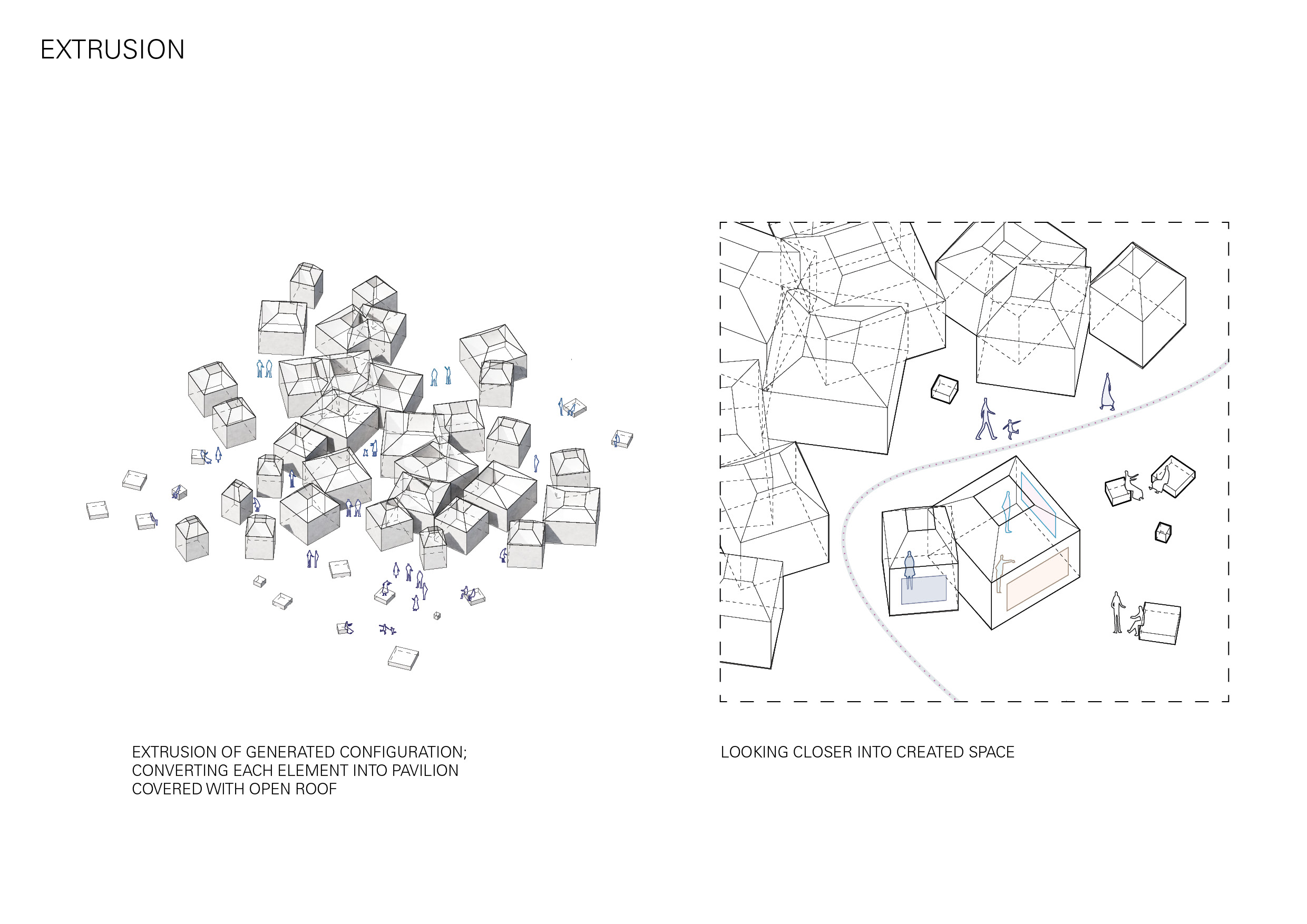
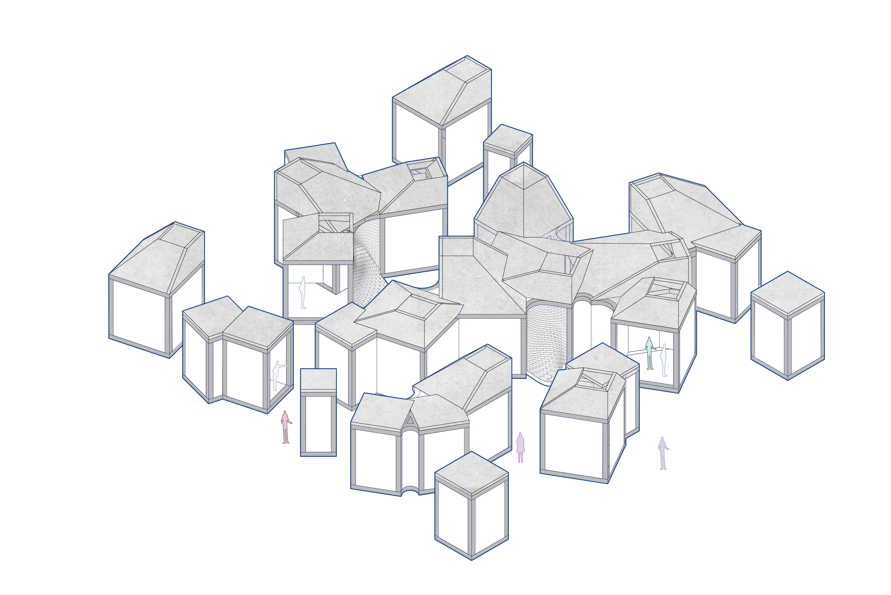
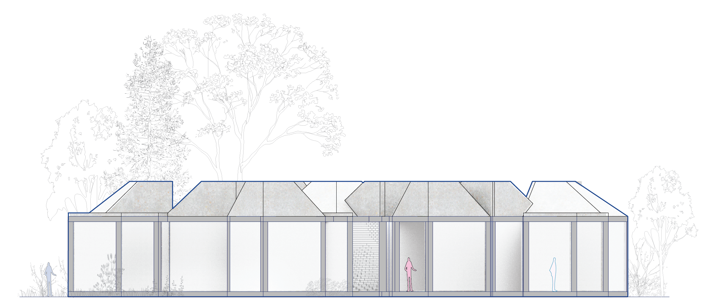
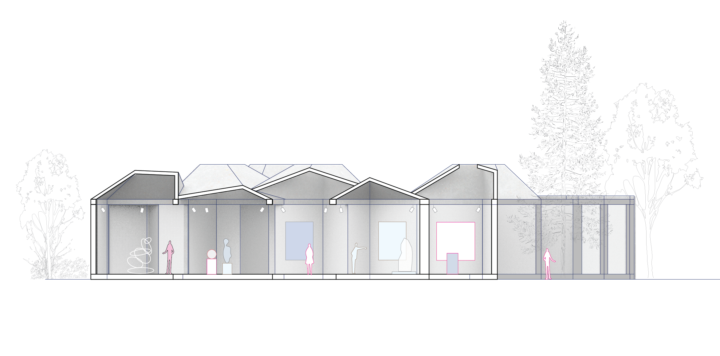
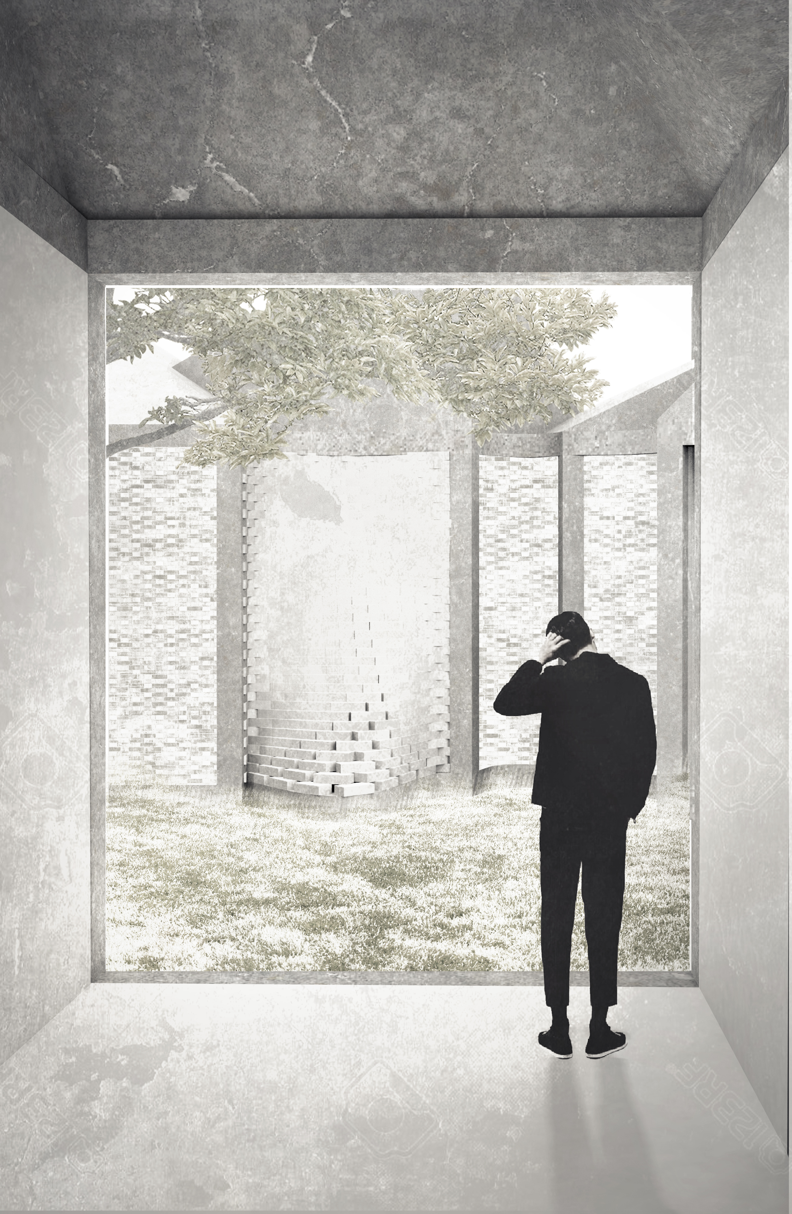
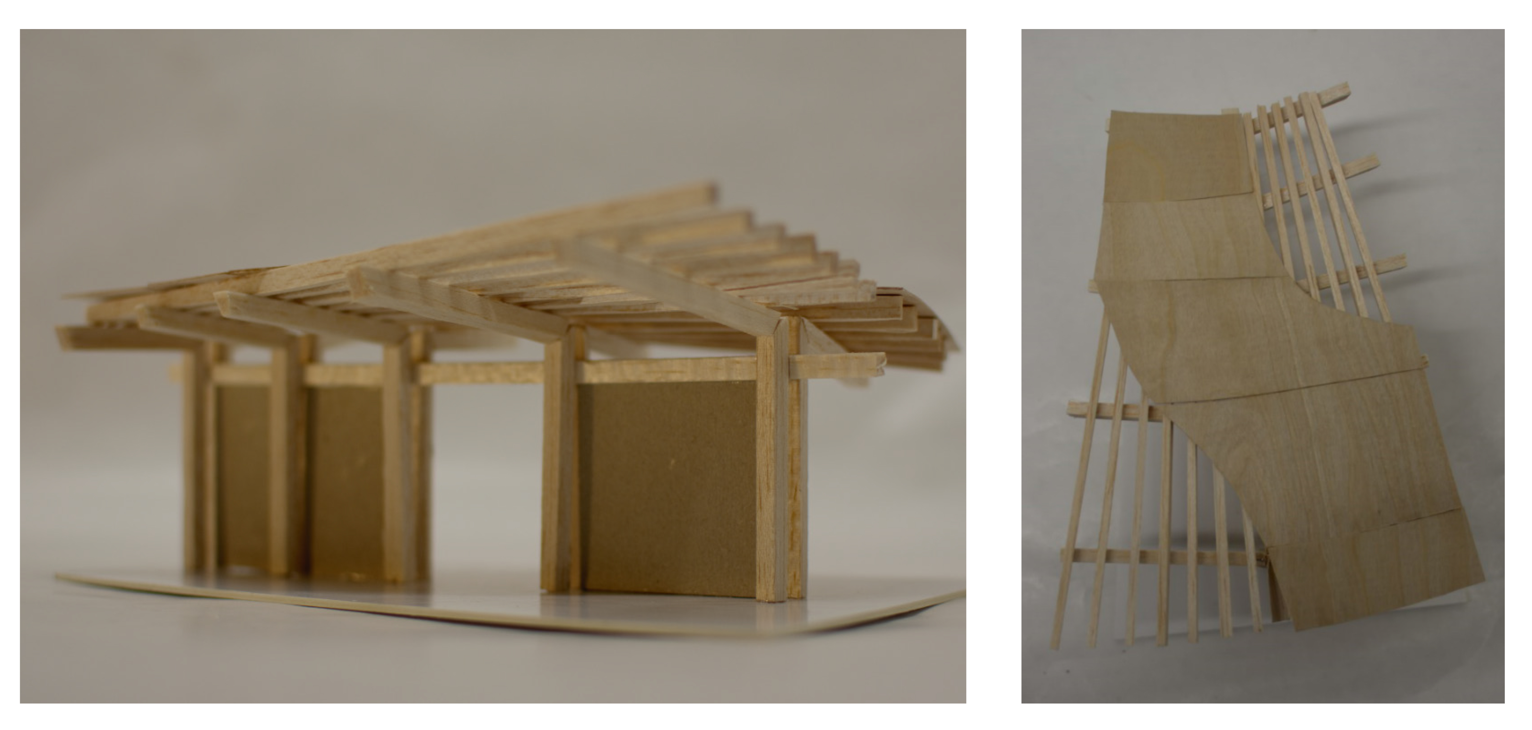
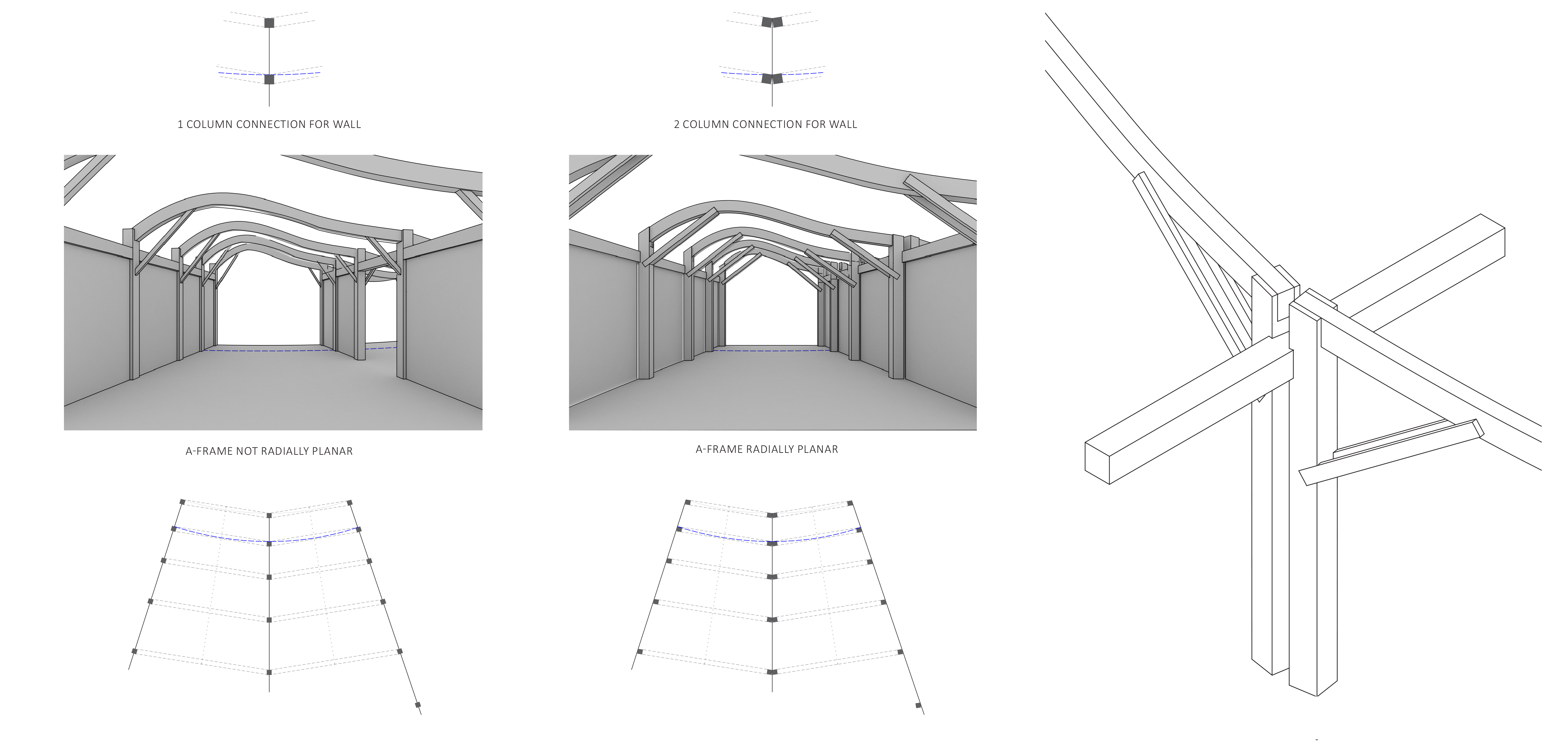
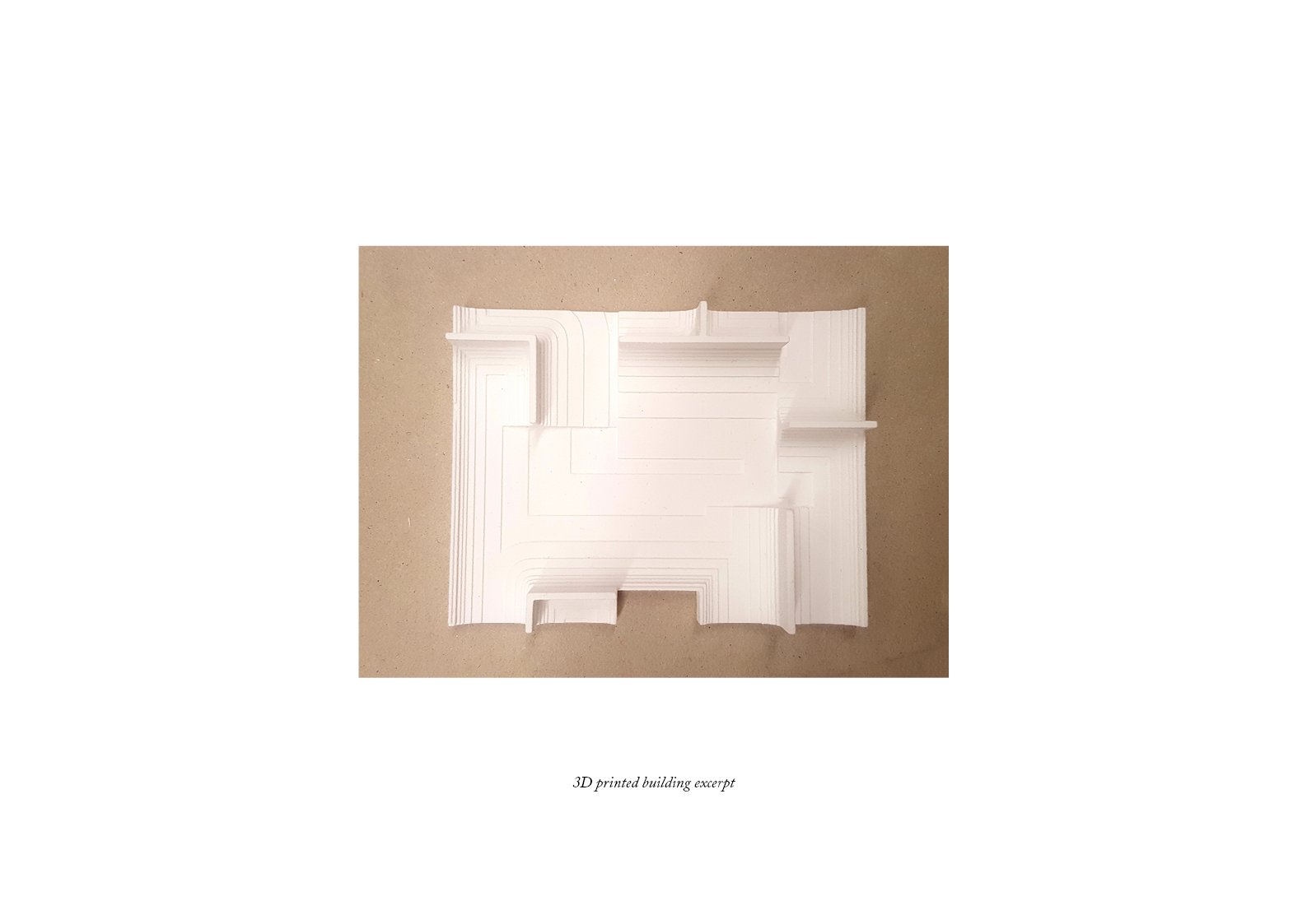
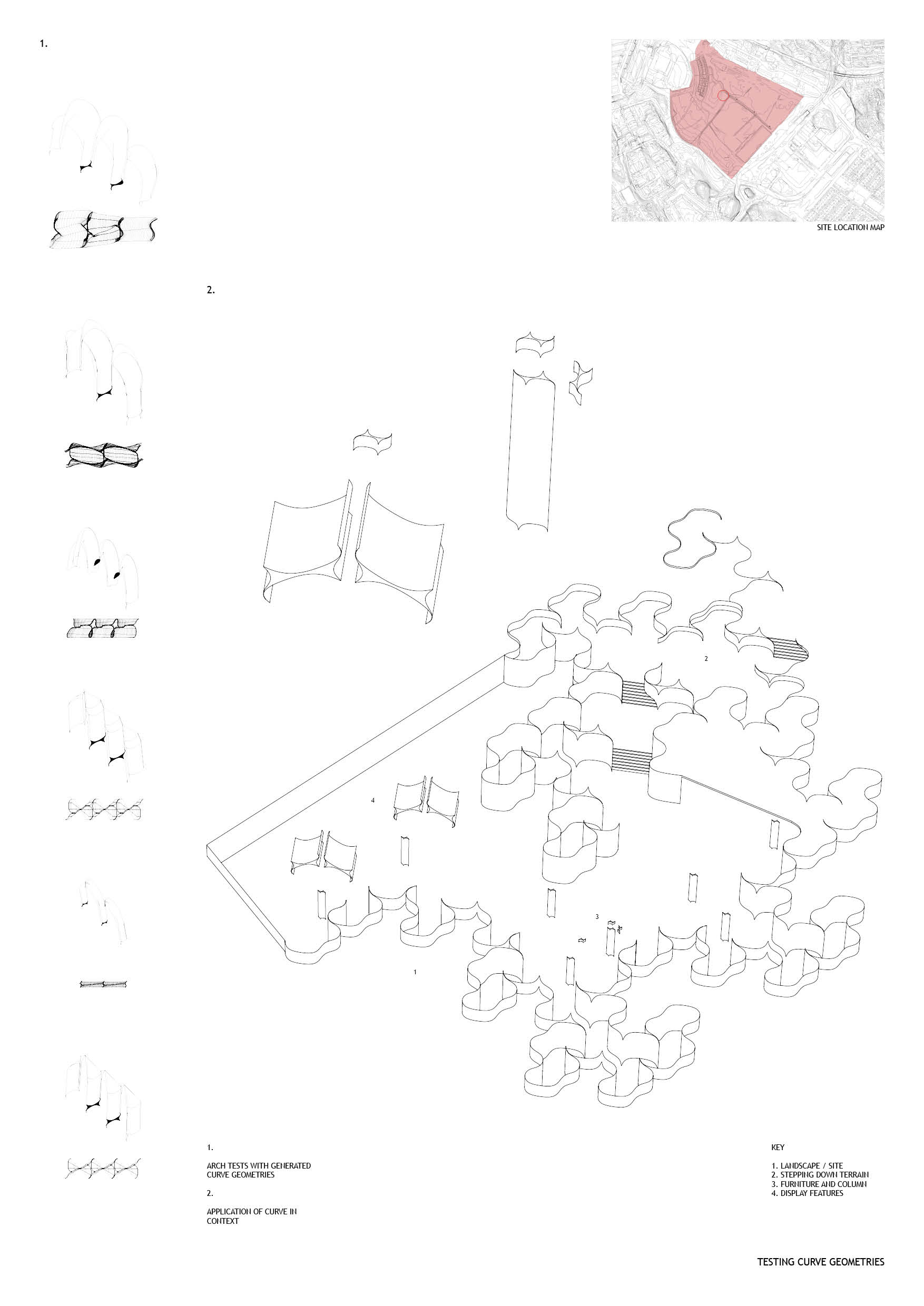
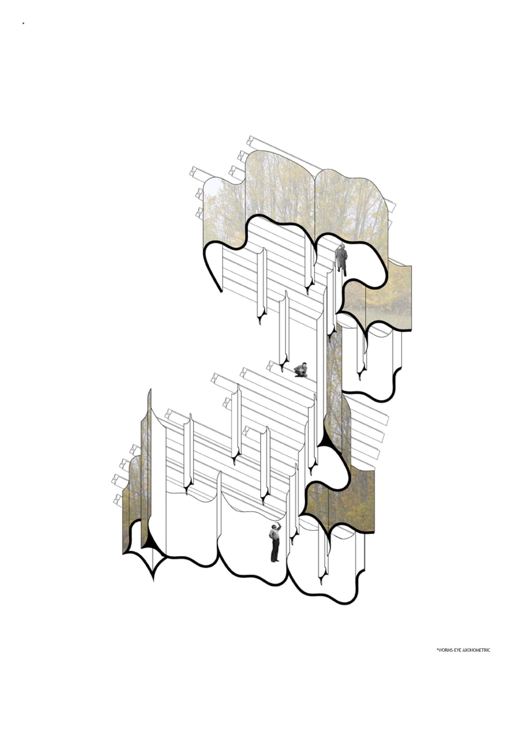
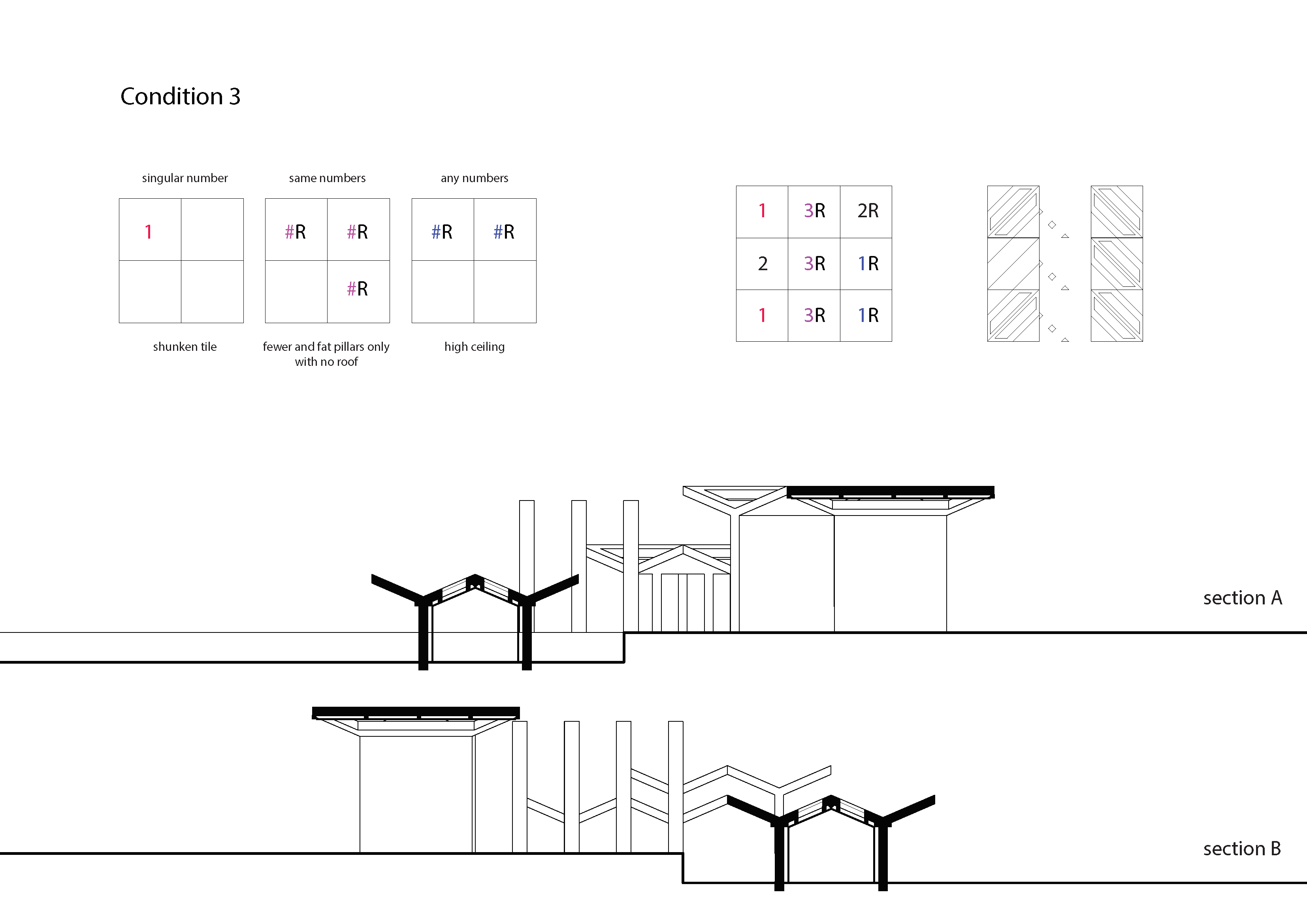
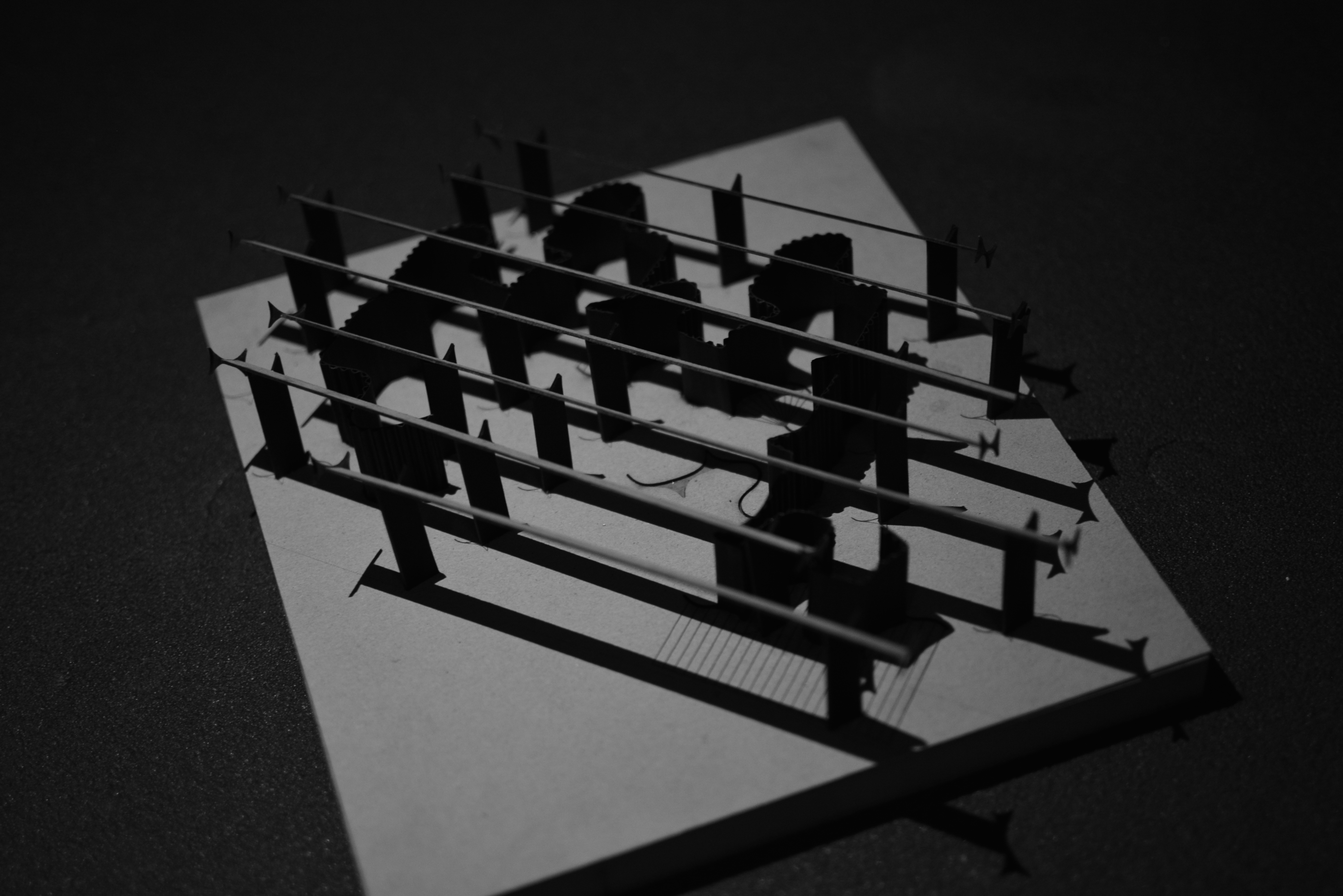
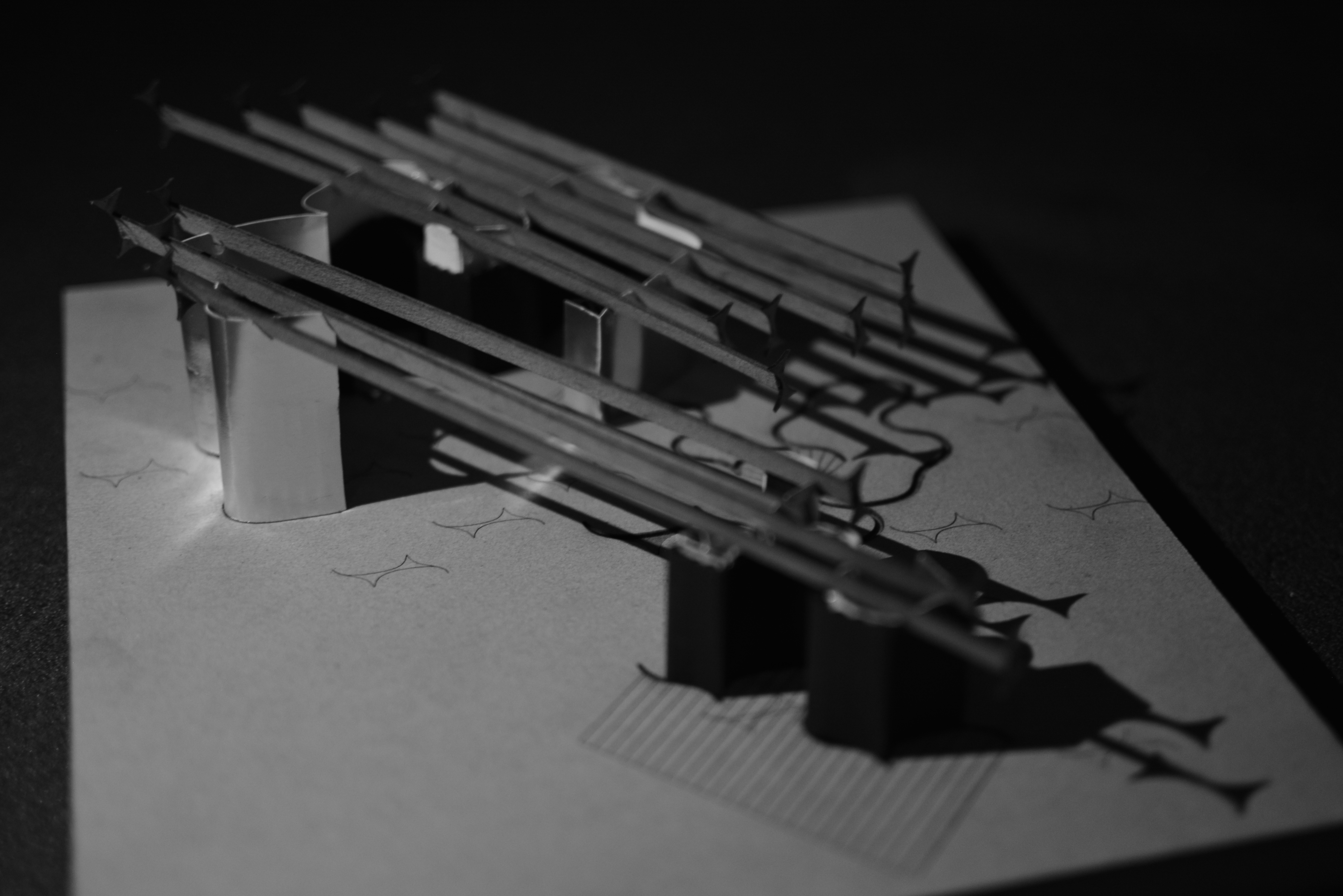
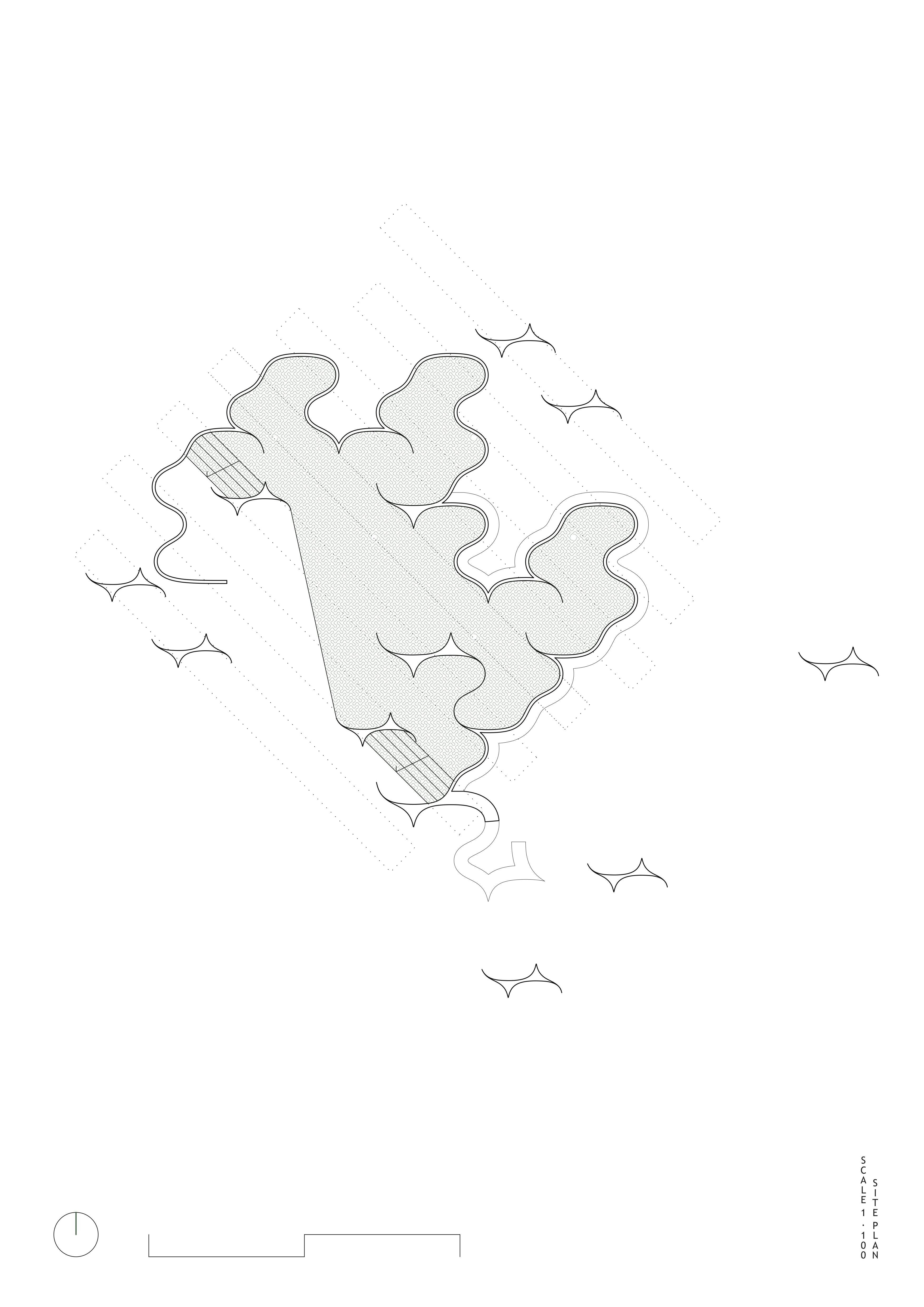
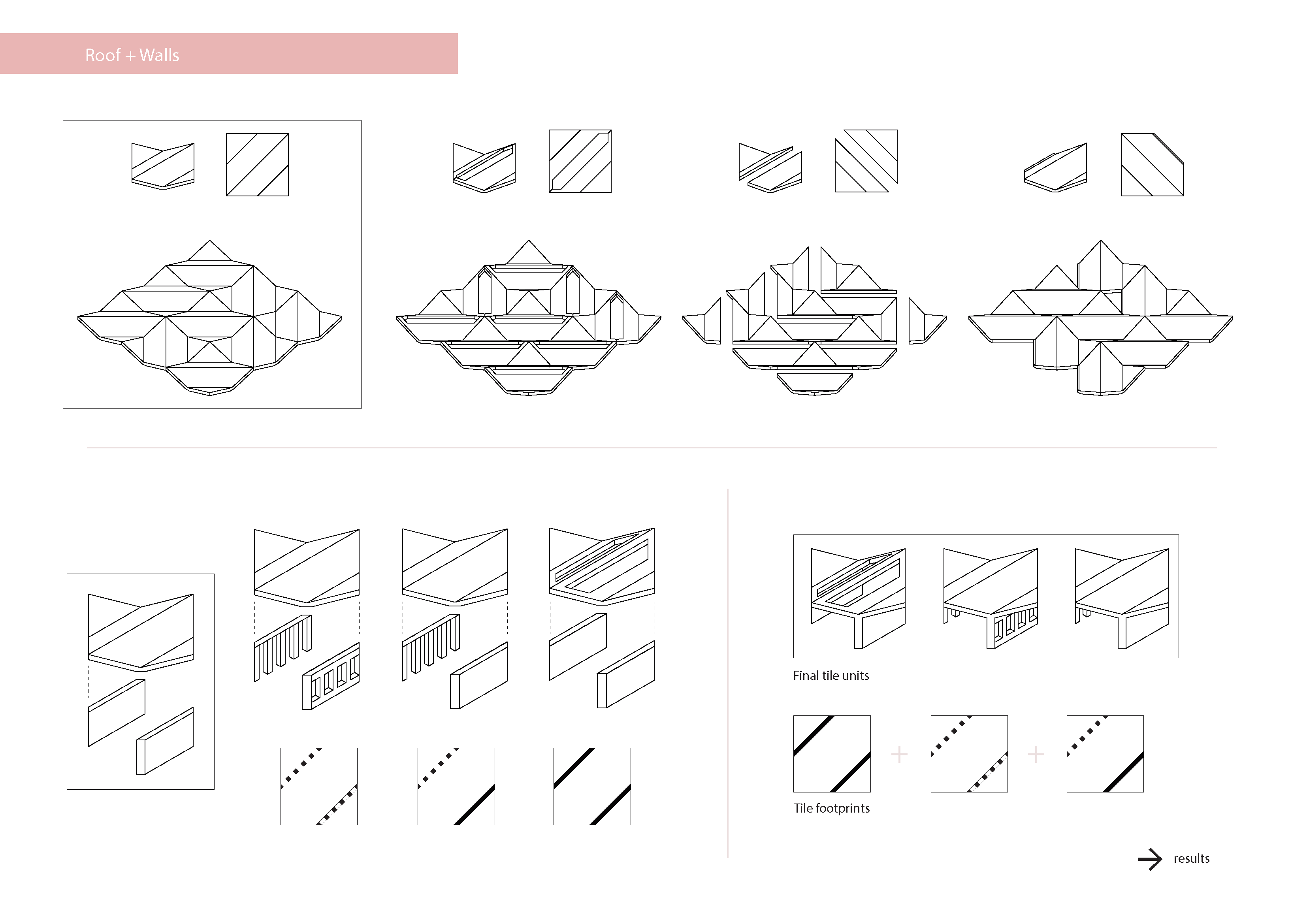
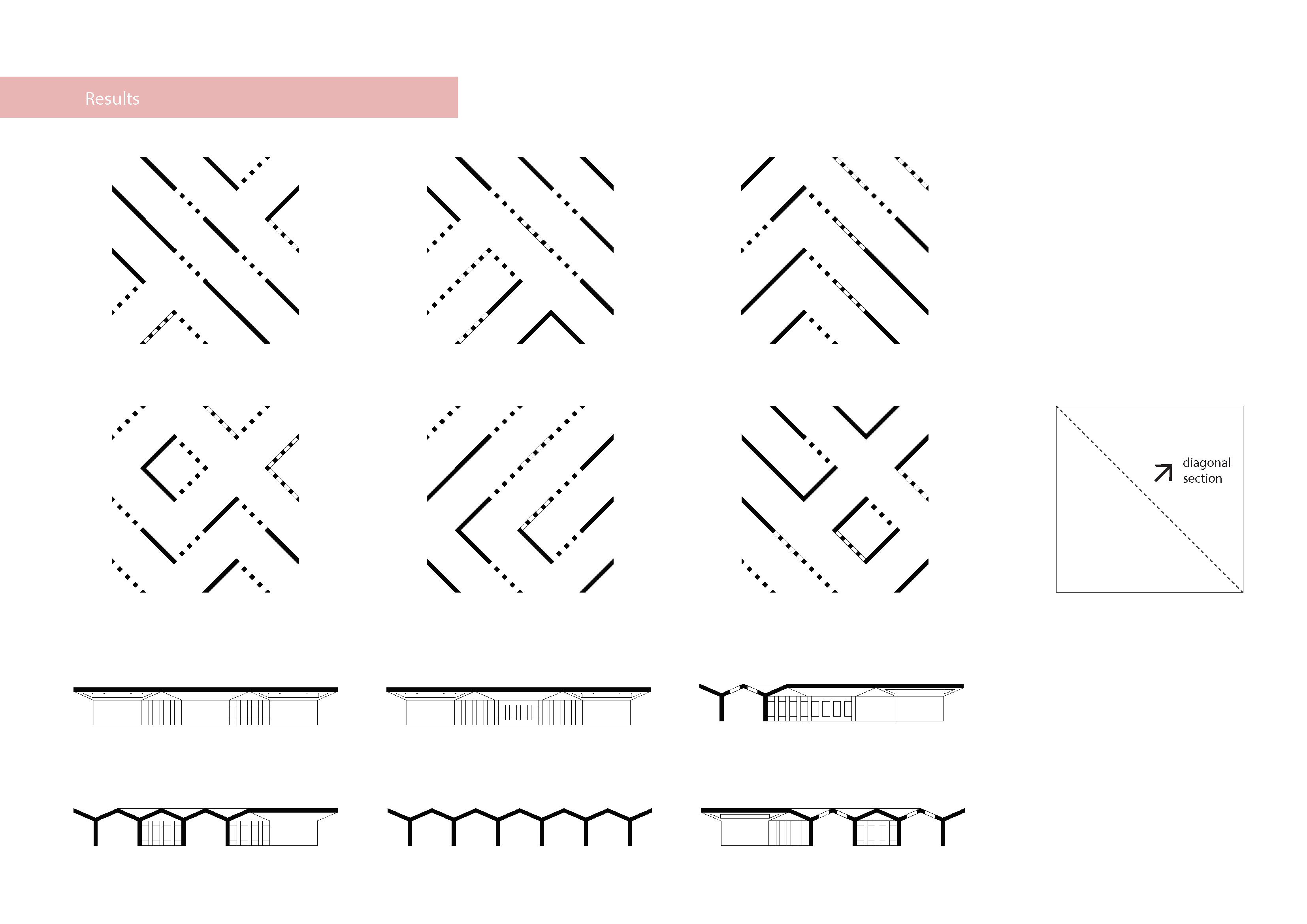
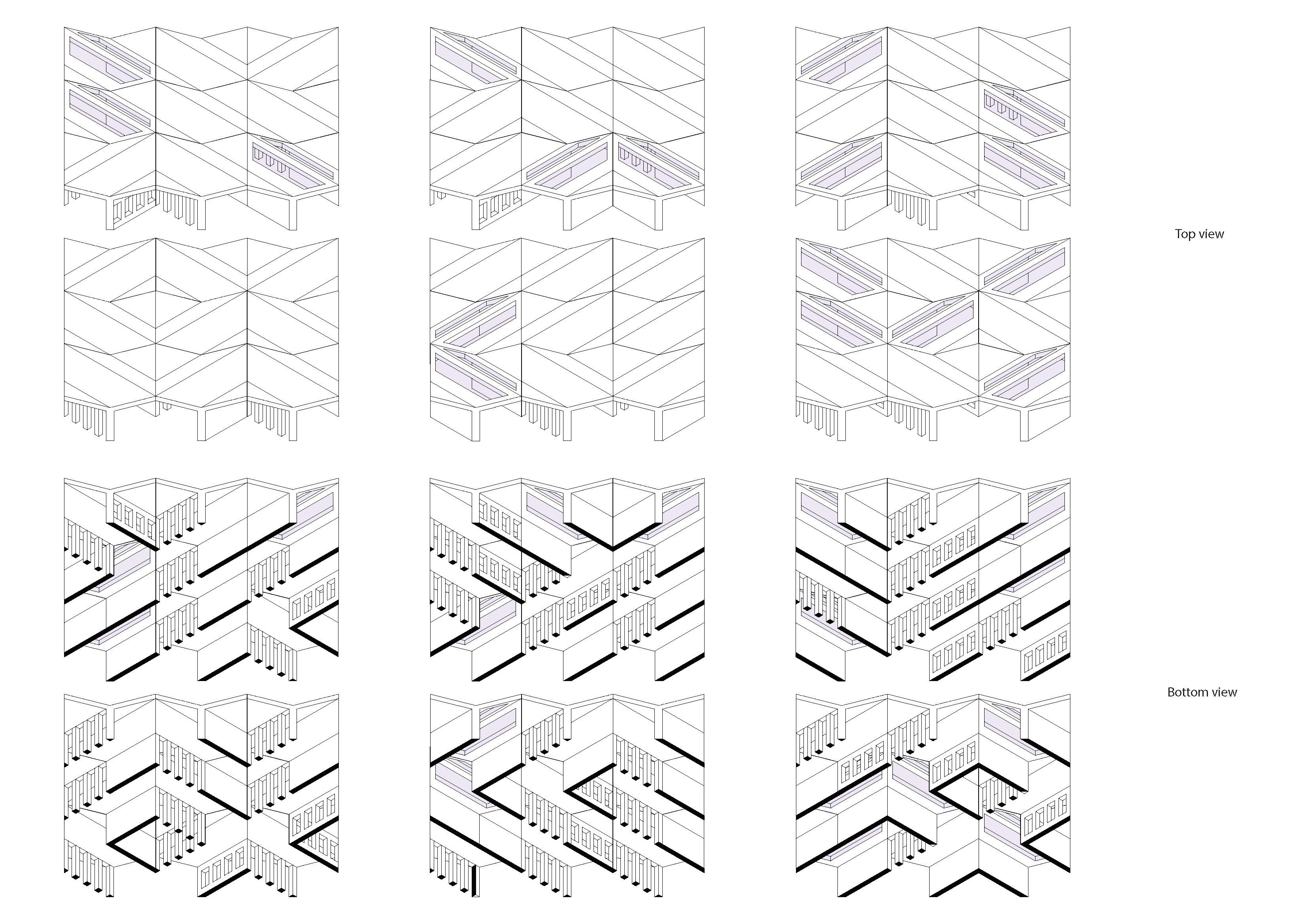
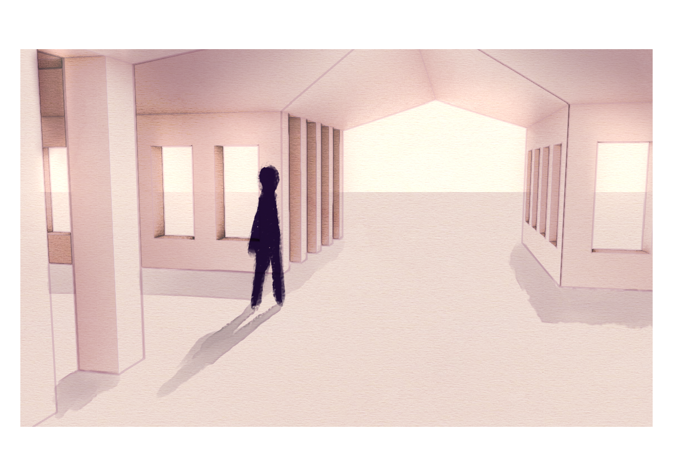
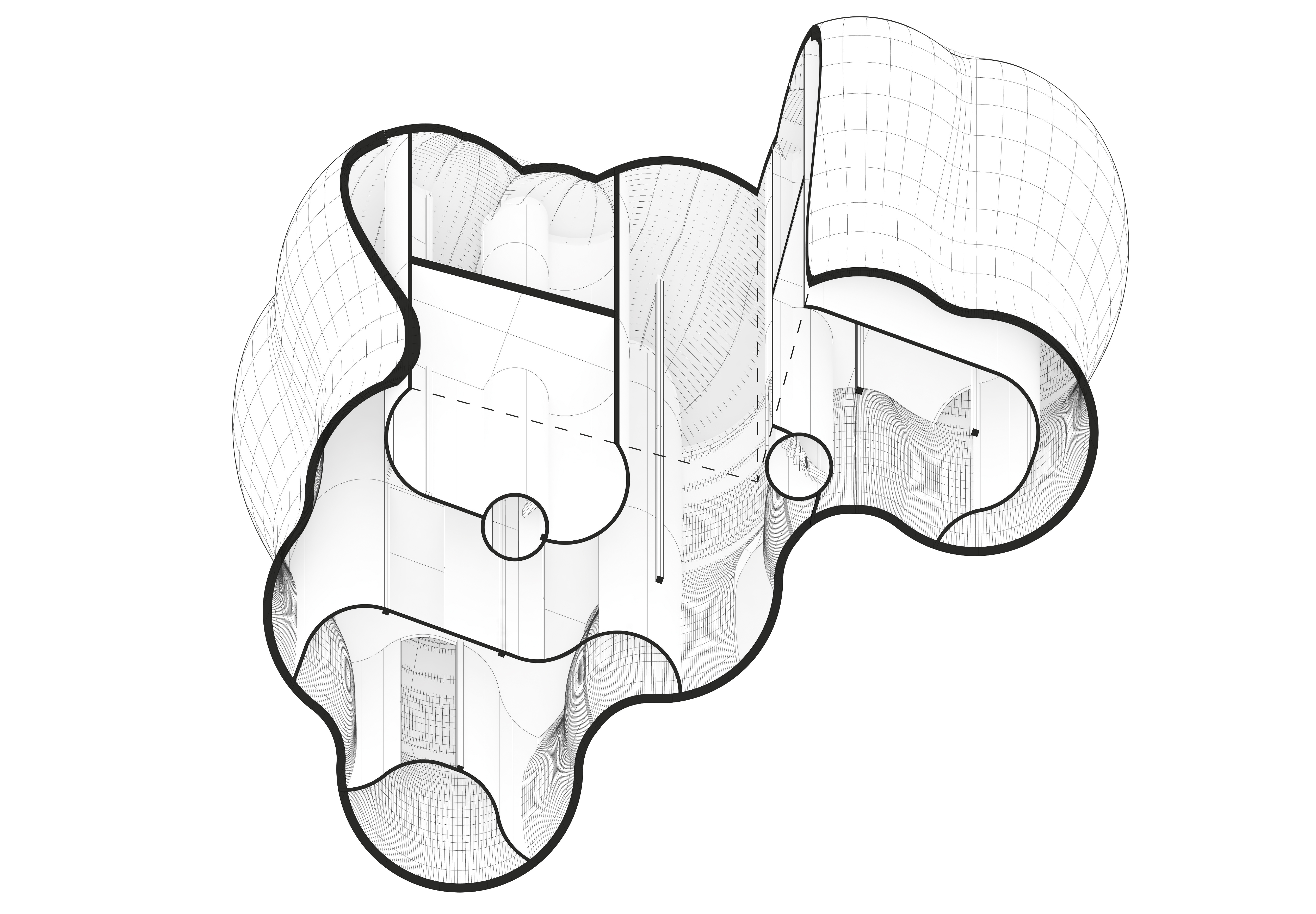
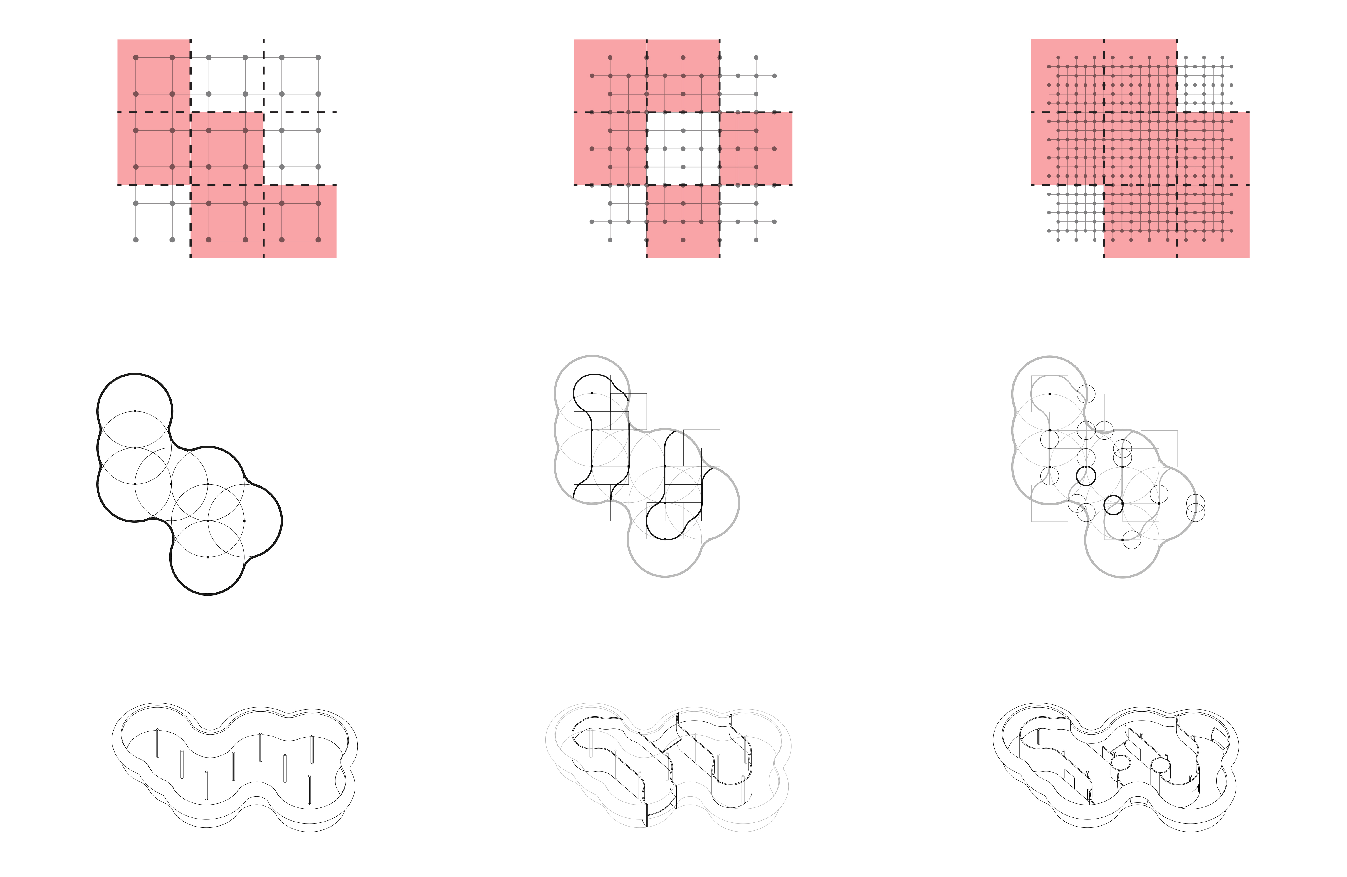
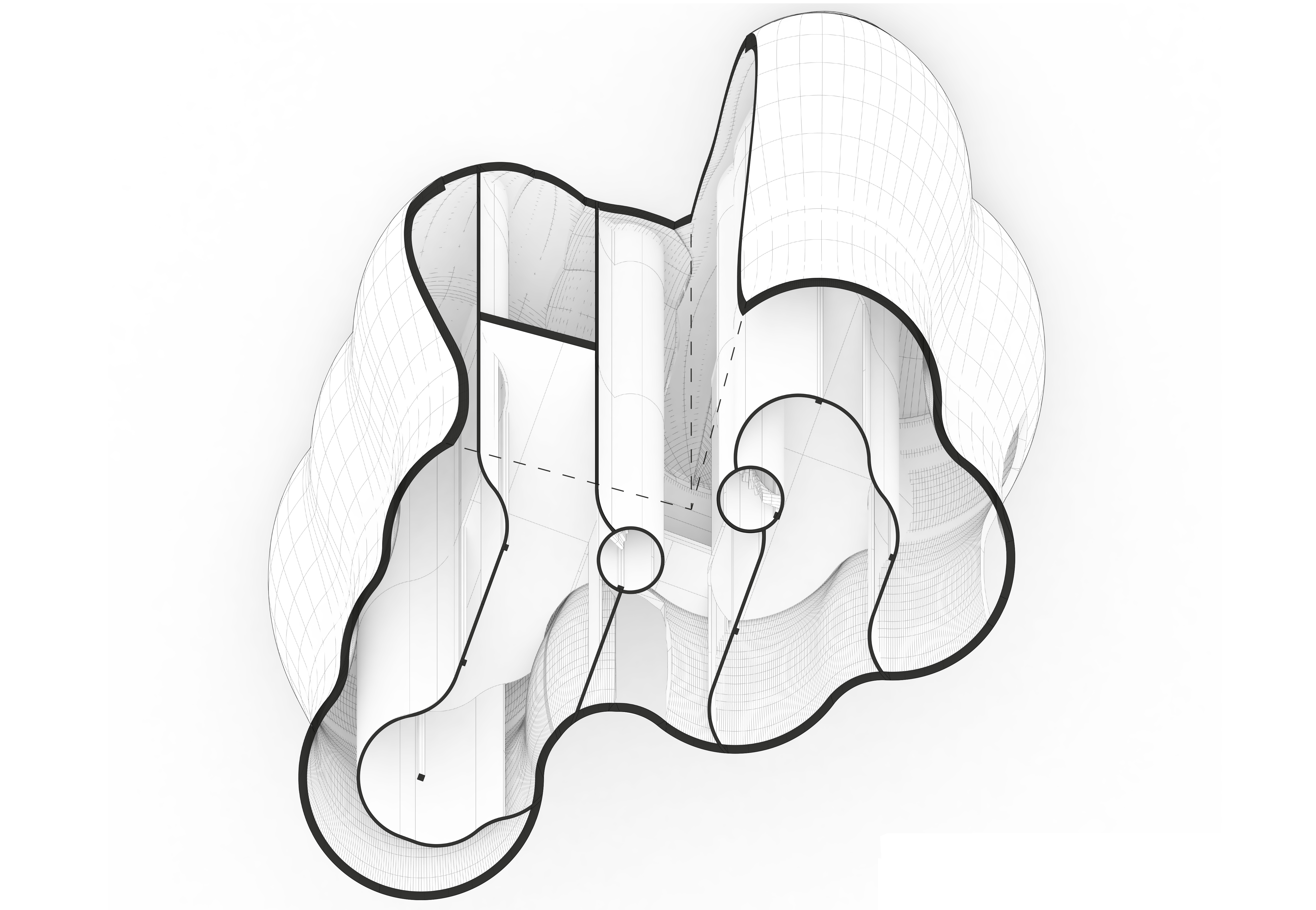
The challenge of using the curved walls as a guide without the roof structure deterring from the spatial experience was a balance difficult to navigate. The design needs to be explored at multiple locations within the curvature, based on site variations and the specific spatial qualities created at each chosen point. How the spaces are occupied, what potential it holds for exhibition purposes etc.

Plan

27 grids later.

Continuing with my experimentation of grids, I have been developing a more complex system which can be used to generate spatial arrangements that respond to specific site conditions and parameters.

Exercise 3 Sheets-4

I have split the building into a primary, secondary, and tertiary layer, each produced through an individual grid which generates different sized shapes.  The 3 overlapping grids are each sub-divided into 9 regions, which can be programmed to determine the probability of a shape being generated in a specific region.

This system means that I can use certain site conditions such as views, orientation & access to instruct the building form.

Exercise 3. Jack Glasspool-6

To convert this into a 3D form, I continued to use the layers generated through the 2D grid. For the primary layer I combined the large shapes to produce an exterior boundary. Extruding this vertically, I offset the boundary at regular intervals and lofted these together to produce a more irregular form. Repeating this with the second layer, I was able to produce interior walls within this boundary, with the final layer used to generate initial circulation openings.

Experimenting with this process on site, I have generated two varying buildings on site which have both been designed using the same parameters.

Example 1:

Exercise 3 Sheets-6

Axonometric View:

Exercise 3. Jack Glasspool-10

Example 2:

Exercise 3 Sheets-7

Axonometric View:

Exercise 3. Jack Glasspool-9