P4.T3+Final Presentation.More?

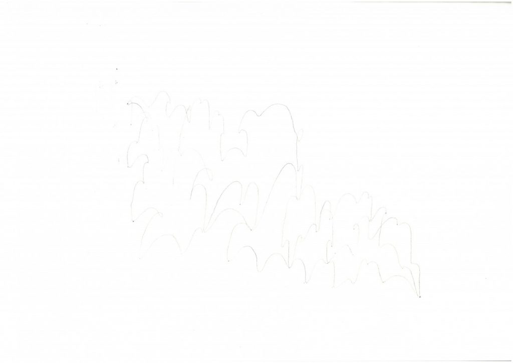
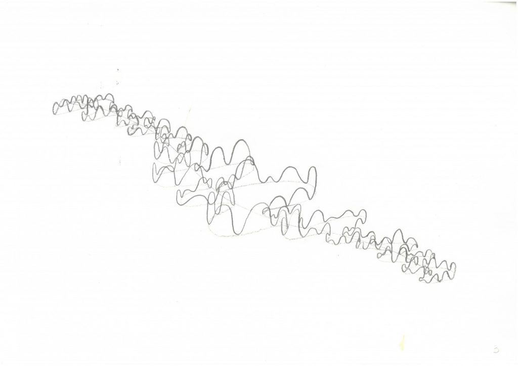
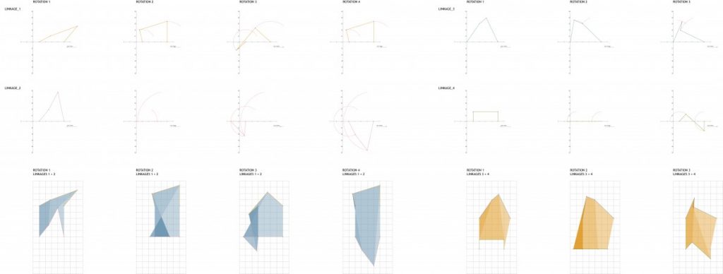
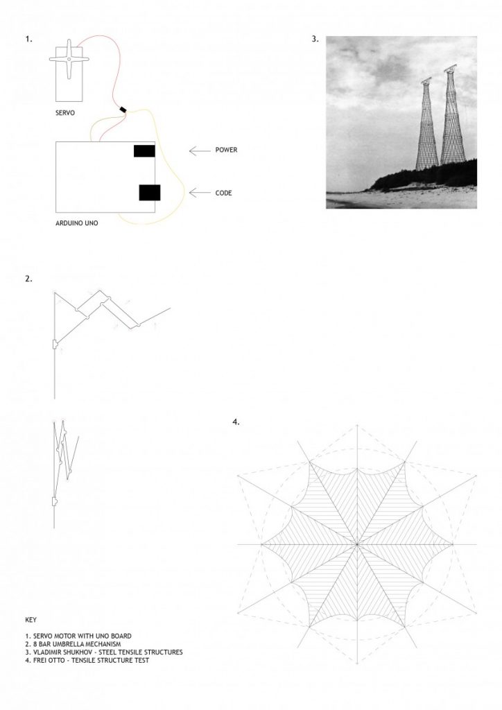
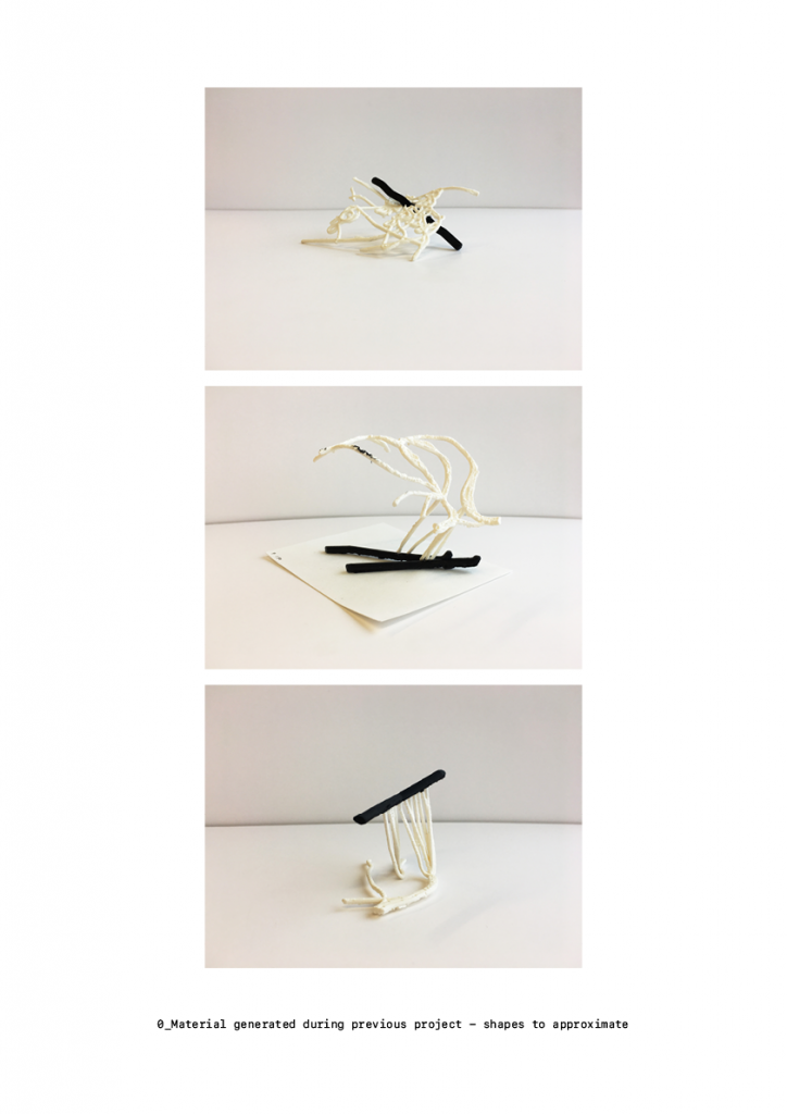
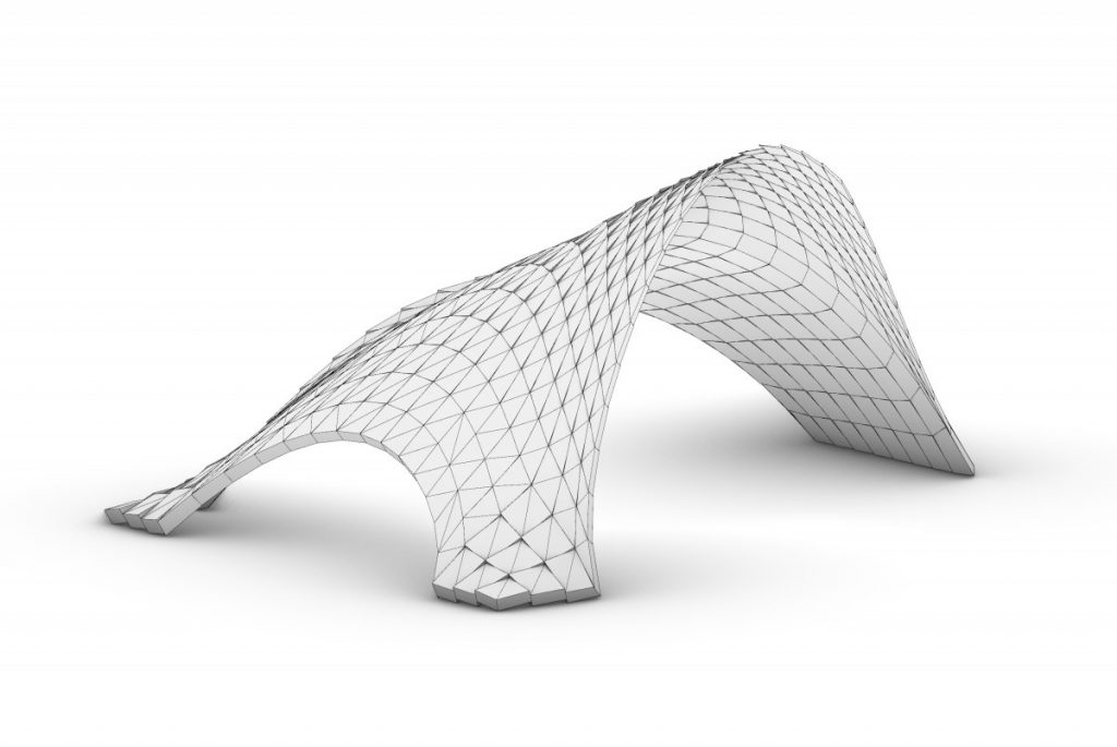
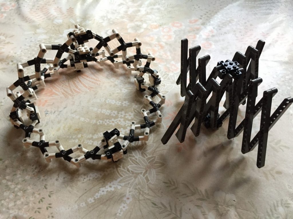
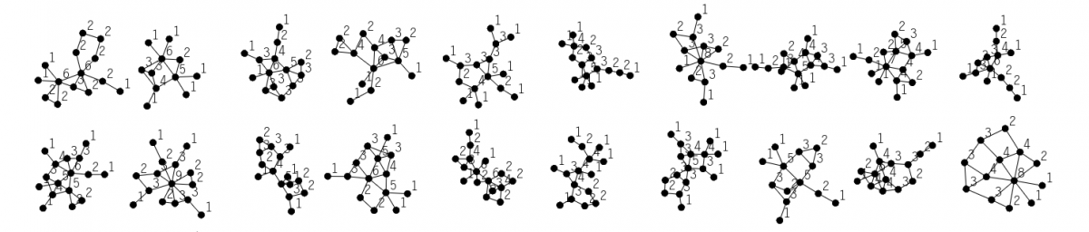
In the previous exploration we observed the spatial and form giving possibilities of the four bar linkage when combined with the servo motor.

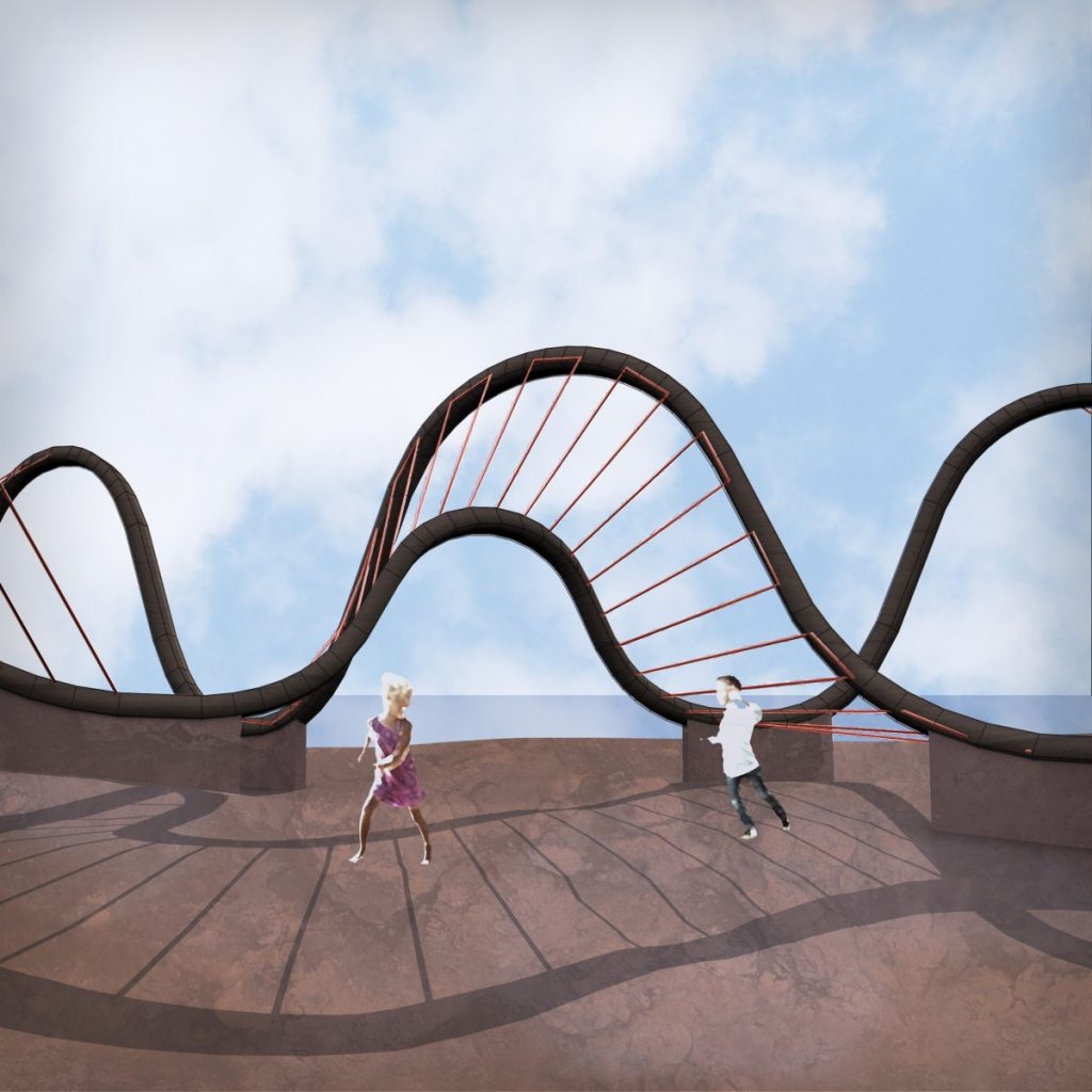
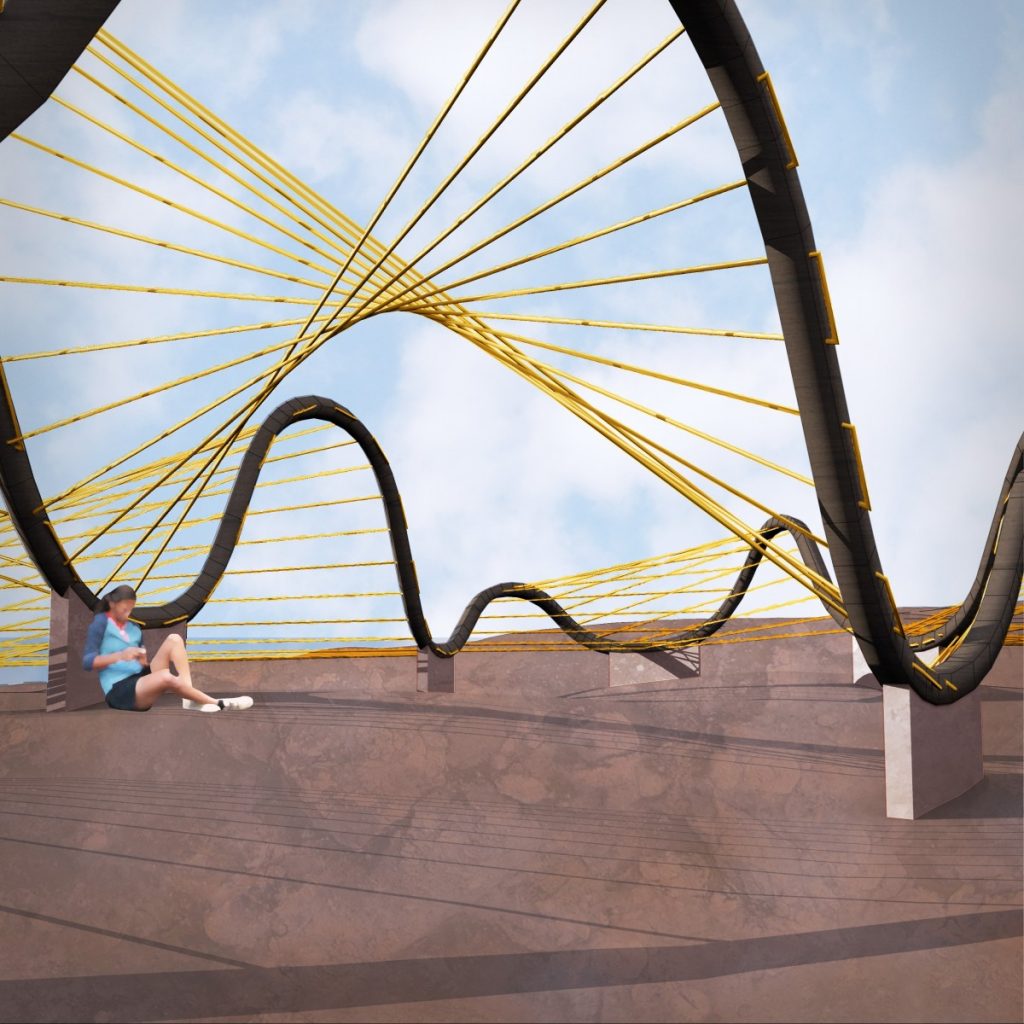
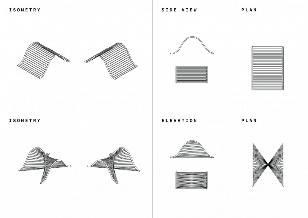
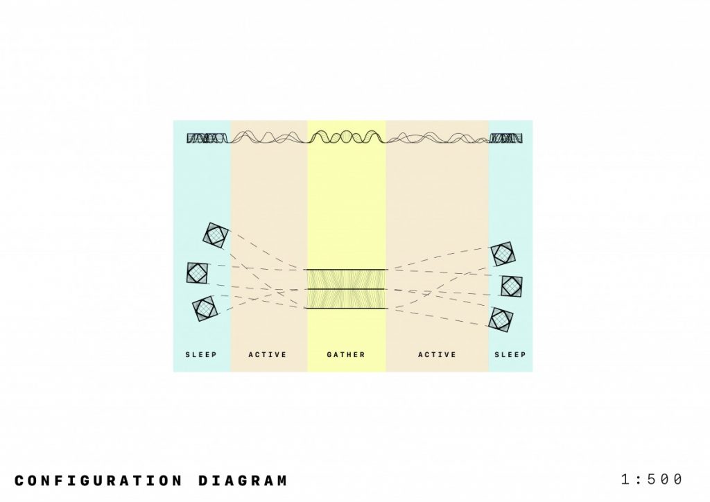
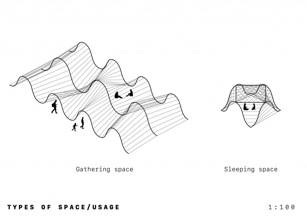
The first test was a planar study of space and allows a reading in plan and in section along a flat plane. When we bring in ideas of tectonics and thickness, we can easily extrude up and allow our architectural judgement to build on from this point.

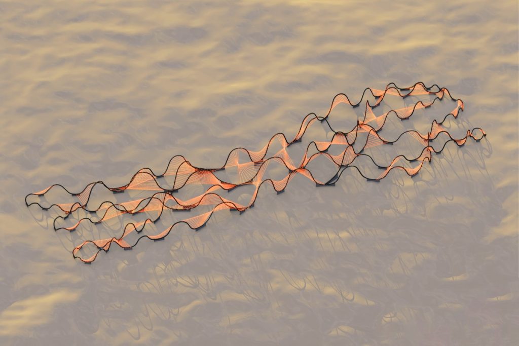
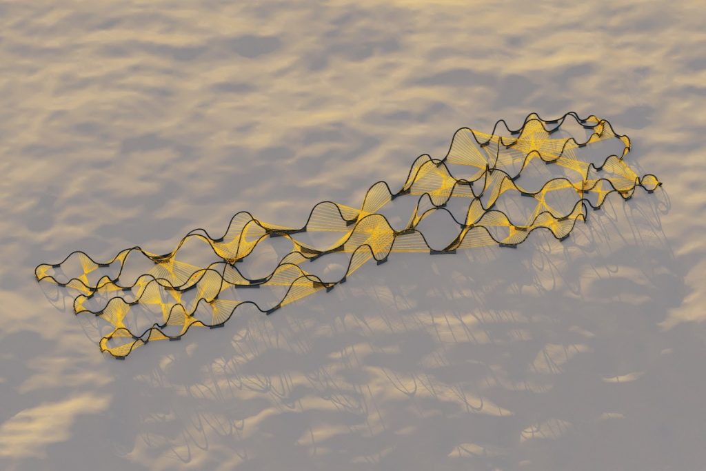
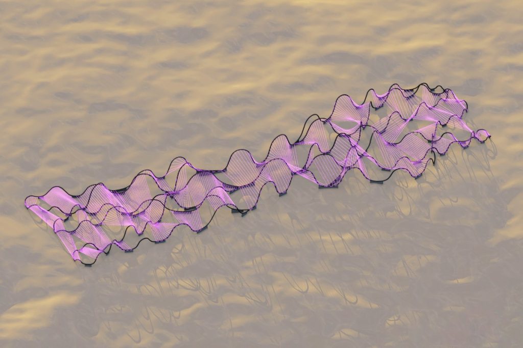
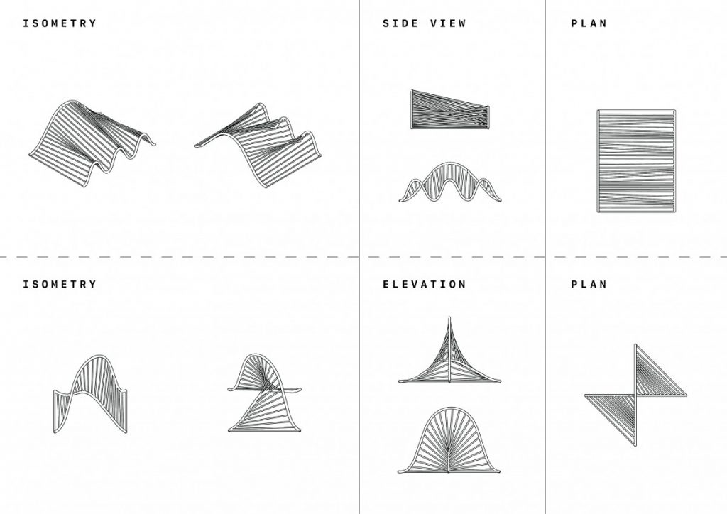
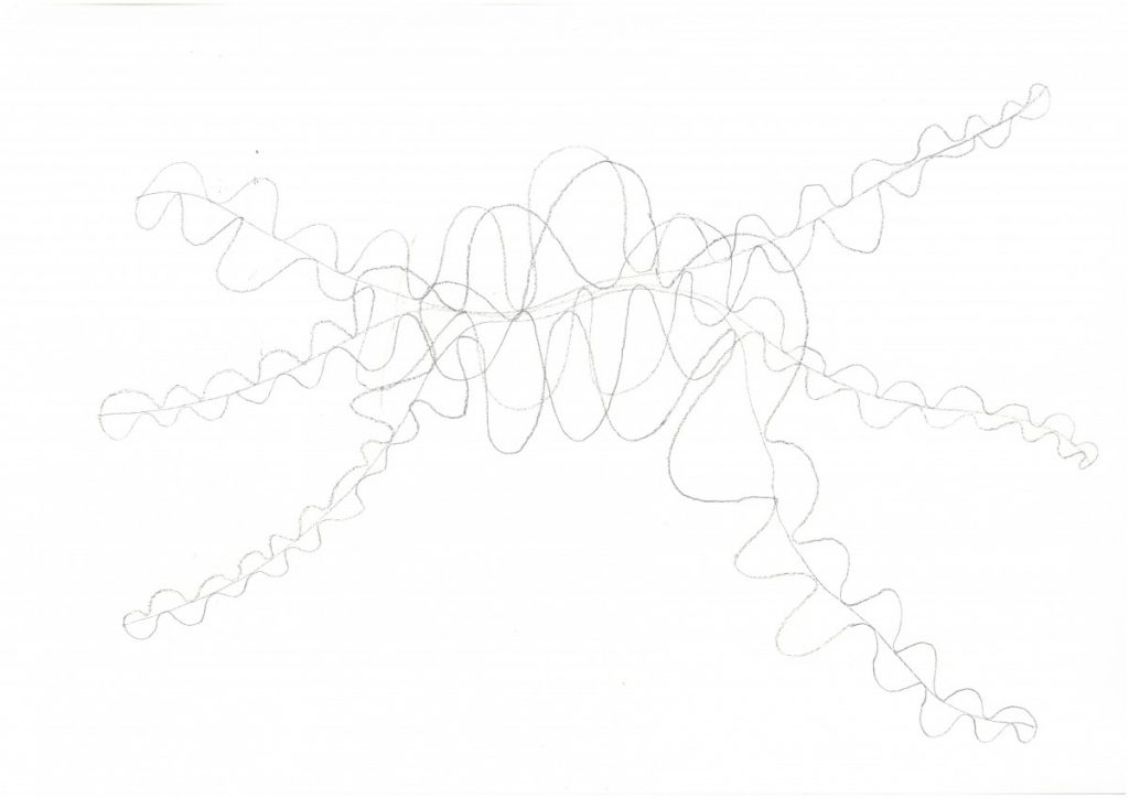
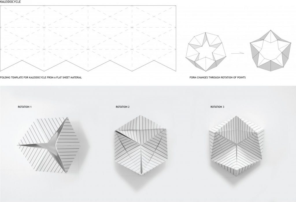
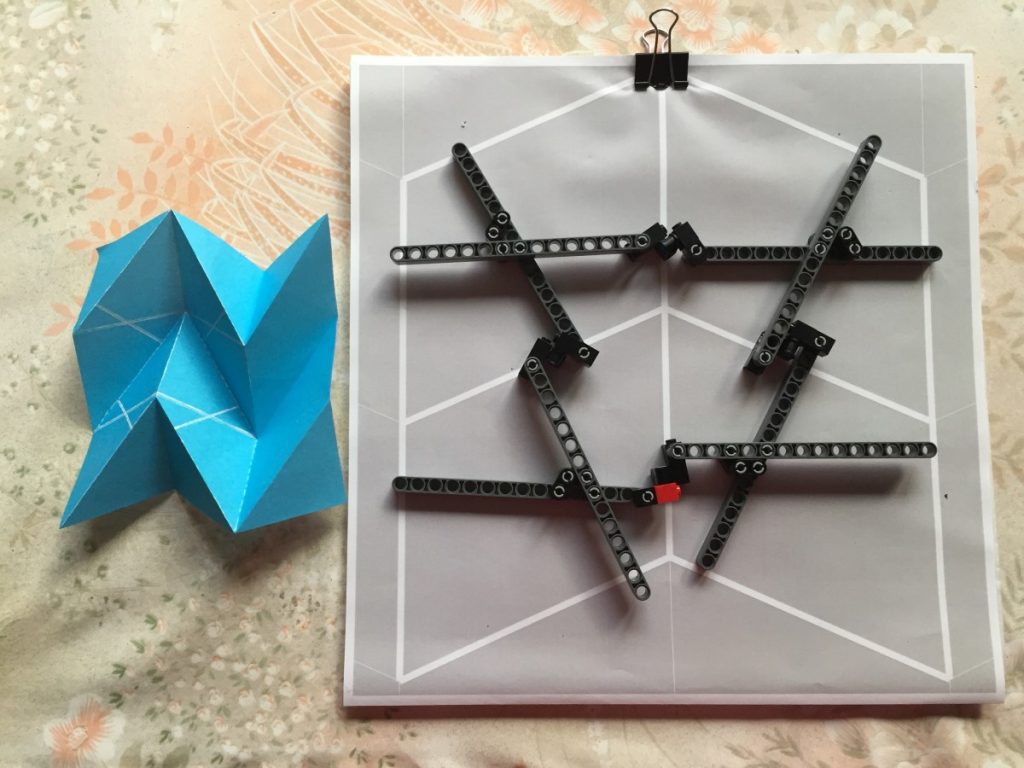
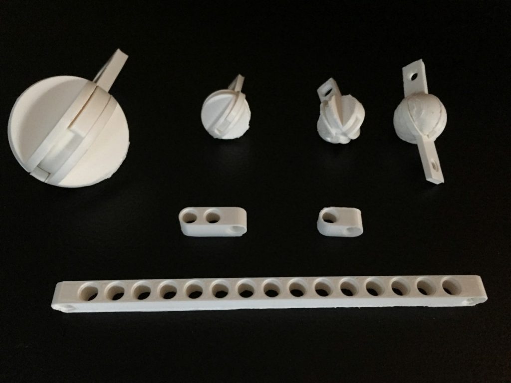
The second test was a study in multiple dimensions and axis. Attempting to assign material qualities was a challenge and therefore this direction seemed like a viable path to further explore.

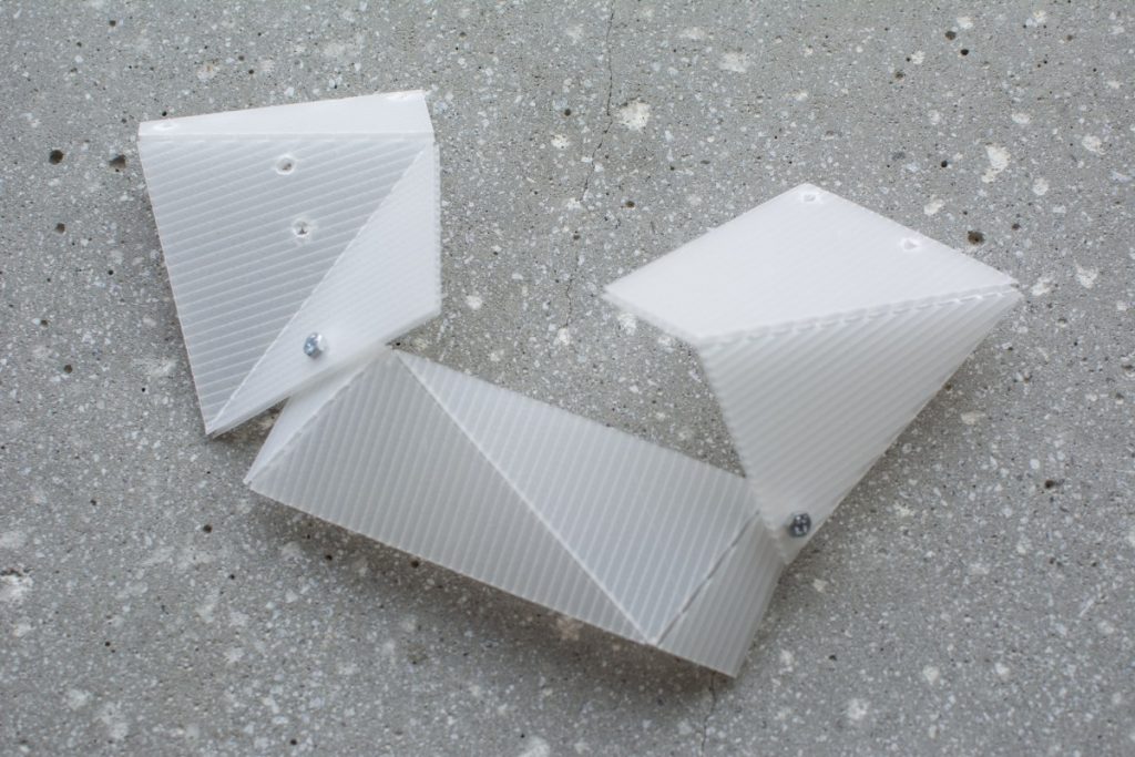
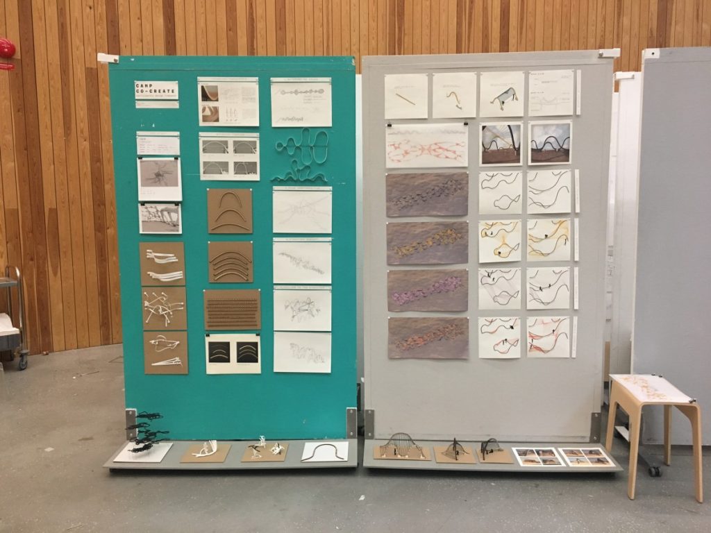
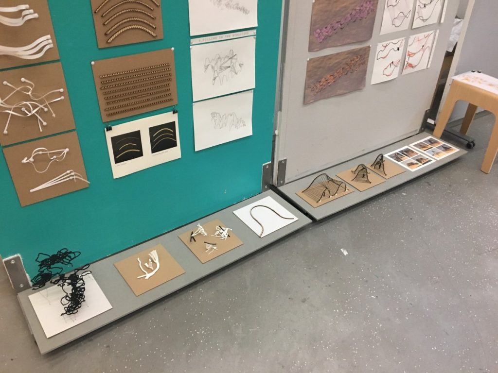
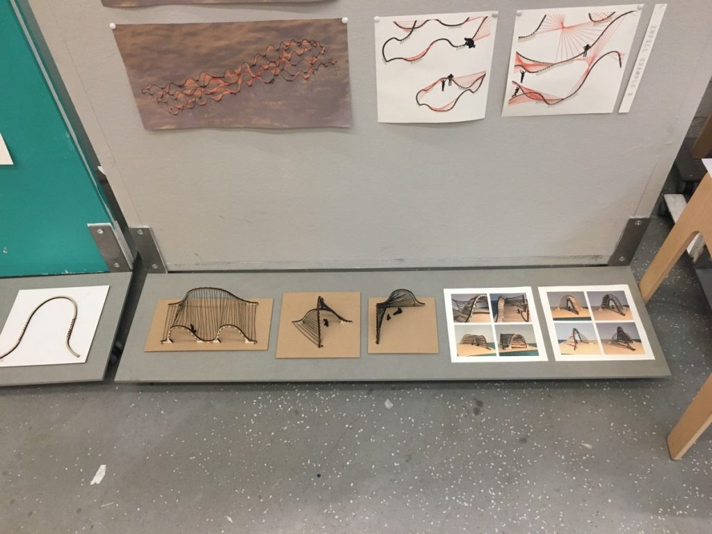
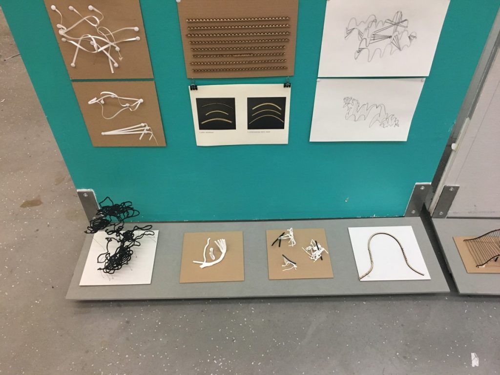
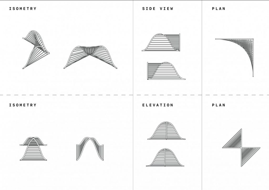
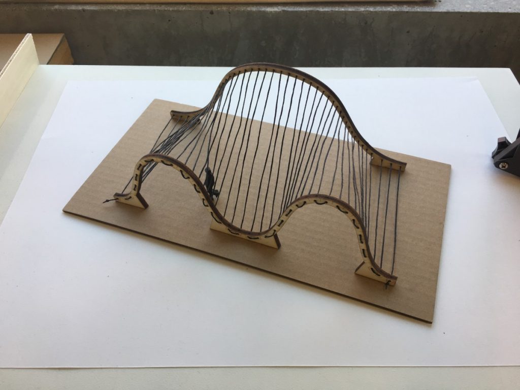
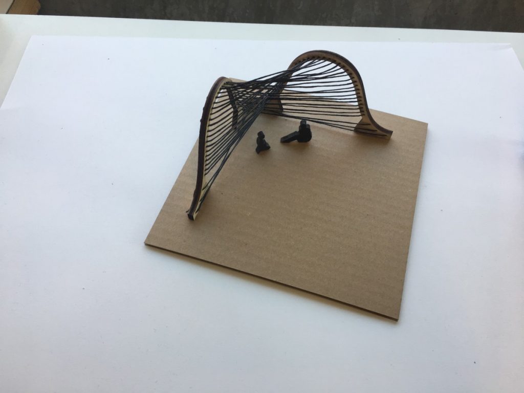
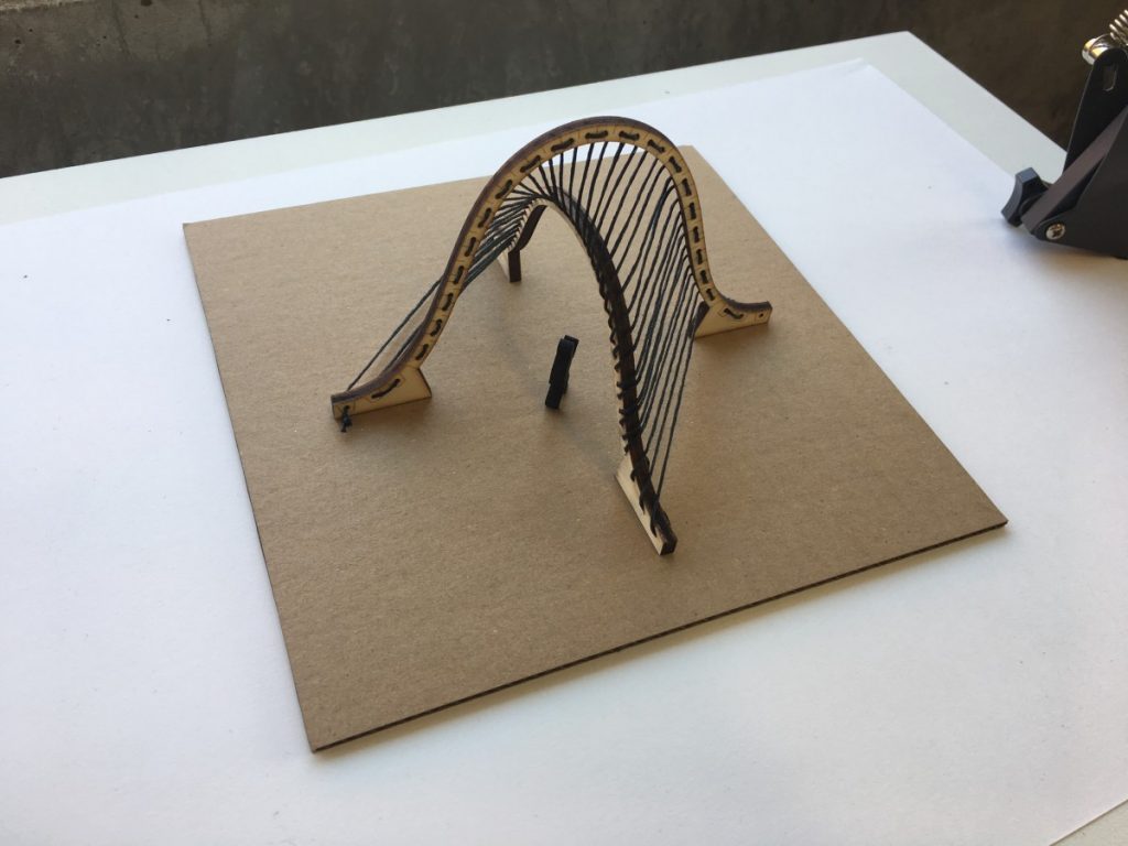
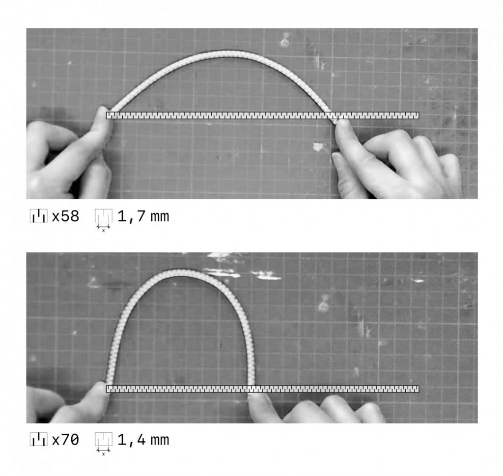
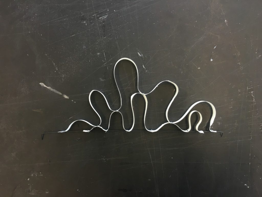
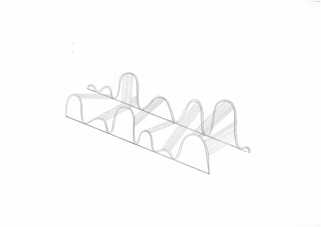
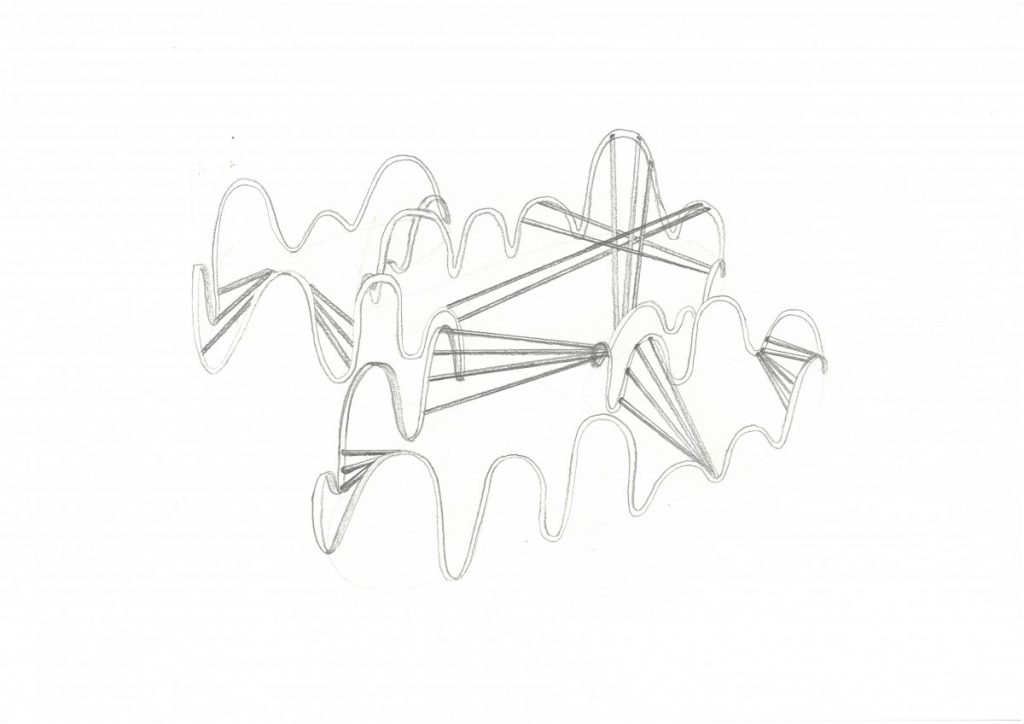
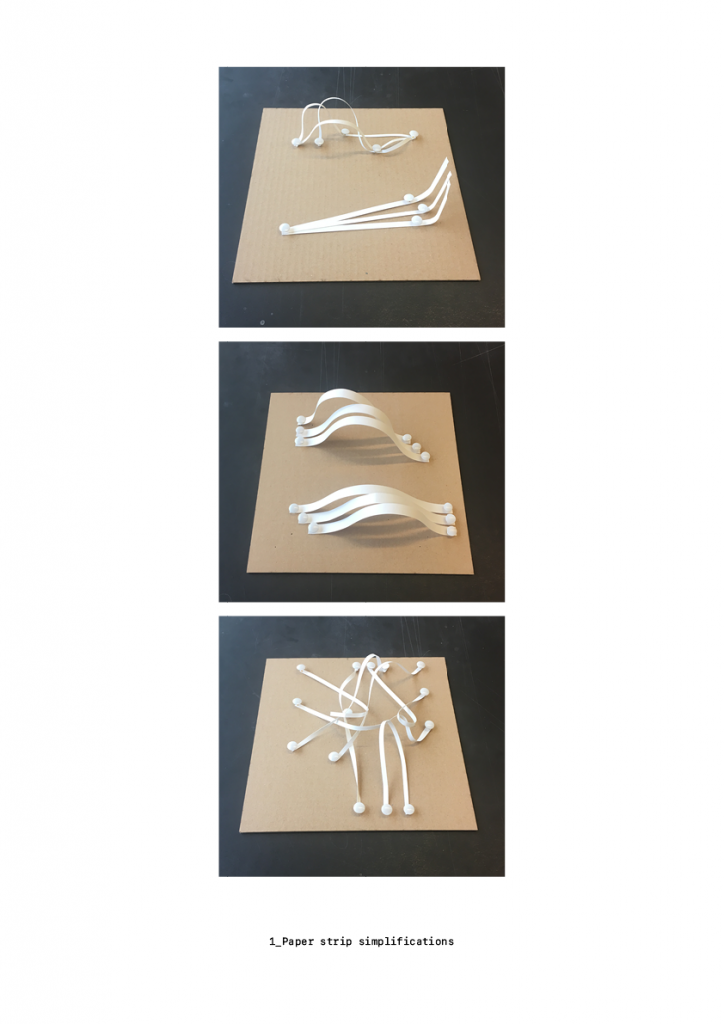
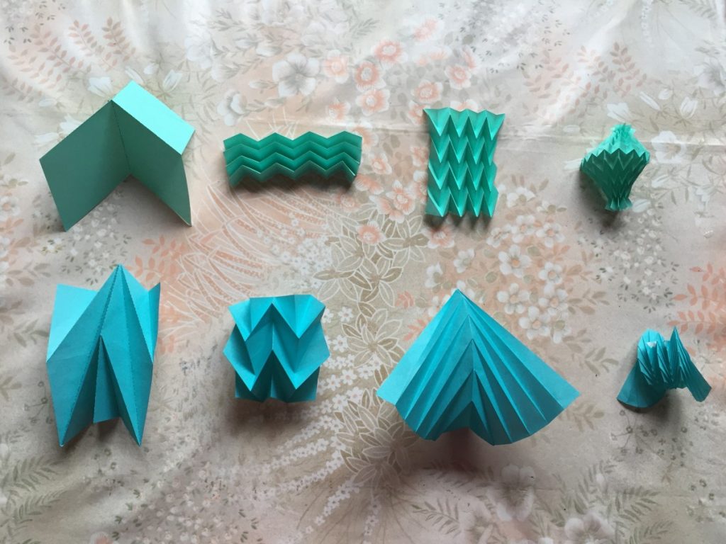
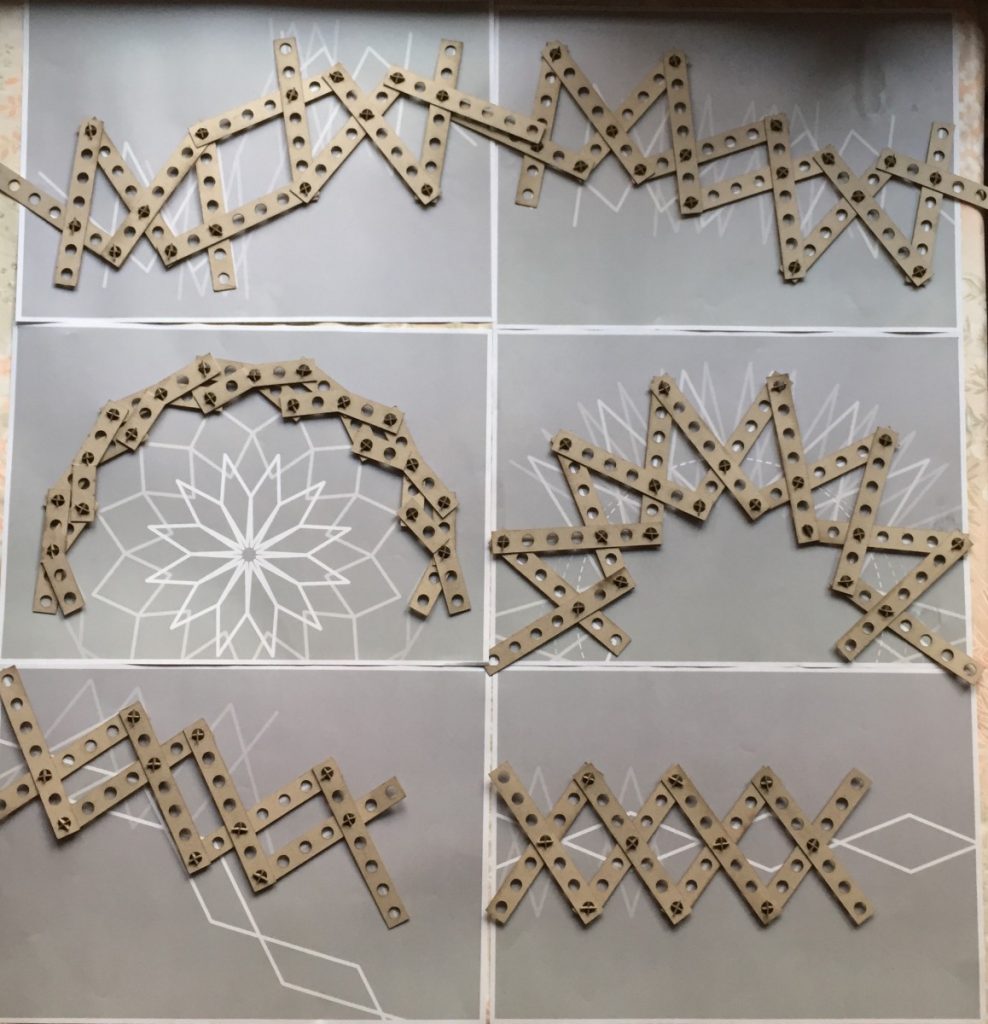
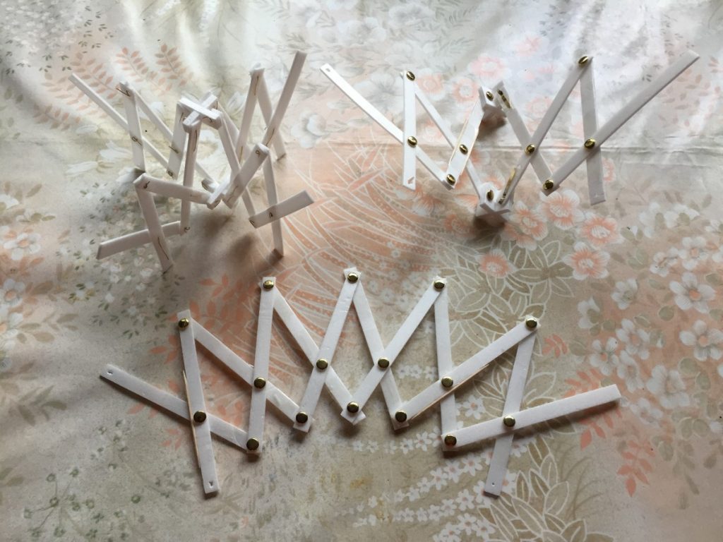
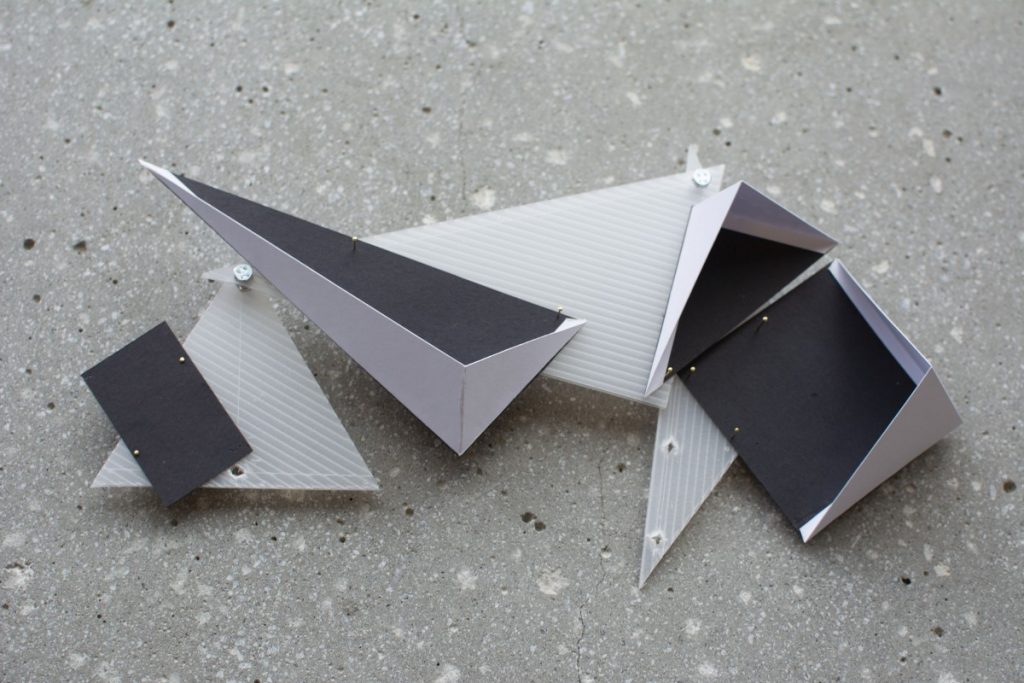
I decided to move the project forward by testing the idea of the four bar linkage across varying planes through simple paper models.

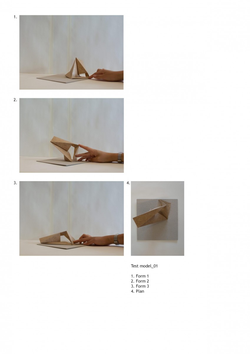
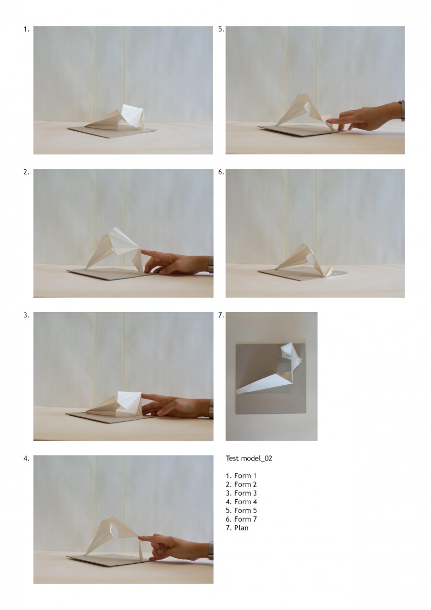
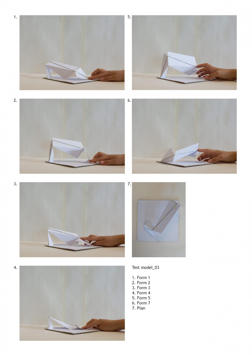
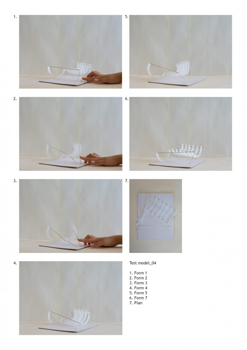
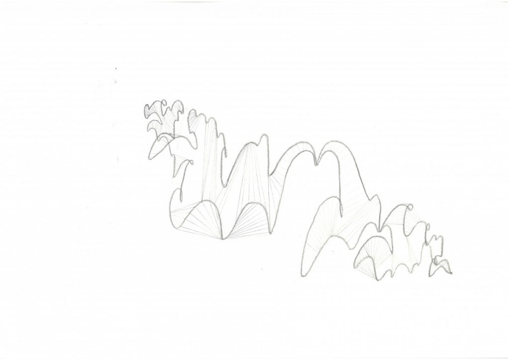
Each of these tests brought about questions of stability, connection points, anchor points, material qualities, thickness, how it meets the ground etc. Potential for the use of colour, thickness and additional elements that extend out from the four bars themselves can be observed. Although a prototype could be developed exploring a solution for such possibilities, I have not been able to push this study to that extent.

Project 3 and 4 has been a sort of research project into robotics, motorised movement and the exploration of what this other world of mobility can offer architecture. No end result as such was assigned throughout the process and I feel that that has allowed me to really understand the possibilities of these tools. I have hit many walls and found myself immersed in frustrations over what architectural meaning this project presents but overall, it has been incredibly fun and challenging taking an alternative approach to architectural design.

Camp Co-Create

The result of my process throughout this project is a framework for participatory design, that can be filled in by the camp users to easily and intuitively create different kinds of spaces.

Through investigating quite varying themes and processes throughout these past months, I feel like in the end I ended up coming back to the idea of participation that I was initially interested in at the beginning of the semester.

A final addition that might be interesting to add to the project for my portfolio (or at least to think about) is what different tool kits could be given to the campers, and what effects the tools handed to the campers could have on the building process and configuration.

Sketch to System in Three Scales

I have spent the past couple of weeks turning the sketches from last pinup into a buildable system.

First, I have roughly sketched out how to build the structure. The basic building system in my summer camp will consist of beams that are pre-cut to have holes, kerfing and a ”zip” on each end, as well as heavier cast bases where the zipped beams can interlock and have their shape defined. The beams are transported unbent to the site, and will then one by one be bent to fit their corresponding bases.

Zooming out a little bit, I have also looked at what kinds of spaces can be created using two curving beams with a third material, such as rope, fastened into the system. To narrow the study down I have focused only on parallel and perpendicular beams, but these different types of relations can be varied further by placing the beams at another angle to each other.

In order to investigate the spaces a bit more closely I also built 1:50 scale models of three of the spatial examples.

Lastly, I have begun to look at how to configure these different types of spaces into a larger campsite, using different kinds of spaces and different scales to create a varied structure for the camp visitors. 

Before the final presentation, I will also investigate how another ”shell” layer could be added on top of the tertiary layer of the structure. I’ll also work through the final configuration of the camp, to create a varied structure with some areas that are more designed by me (by adding a tertiary layer that instead of rope consists of a rigid material) and some areas where the camp users can design their own spaces using rope to ”weave” in the structure.

Material > Sketch > System

This part of the project started out with a small investigation into the bending capabilities of kerfed wooden strips.

After trying to laser cut a prototype of a combined zip-kerf system (and failing because of the laser cutter being too imprecise), I decided that I would instead continue the investigation by making quick models and sketches based on the behavior of the kerfed wood.

Drawing inspiration from the previous part of the project, where the structure was literally based on the movement of the swarming agents, I tried to make sketches that combined the expression of frozen movement with the properties of the kerfed wood.

Up until this point, this project has mainly focused on the wooden ”backbone” of the structure, with one element, wood. However, my aim is to add another element to the structure.

In the beginning of the semester, I was interested in exploring participatory design. During this recent phase of the project, I have started to think about my summer camp as a scout camp, which could include elements of DIY building, problem-solving and learning by doing. My thought right now is that the second part of the structure will be filled in by the camp-goers, and that the wooden structure can serve as a canvas or backbone for the creativity of the users.

From now on, I will focus on exploring in detail what types of spaces can be created with these systems, as well as how these spaces can be combined on a larger scale.

P4.T2.Movement

As we moved onto task 2, I started analysing forms of the linkages and combining two sets to test the spatial properties they exhibited.

The rotation of the linkages needed to exhibit some form or motion and resulting change that would offer a variation in form and surface and space, as in the previous study of the kaleidocycle.

The servo was mounted to a clear acrylic frame and I began to run tests of forms using the basic principle of the four bar linkage.

As observed from the tests above, the spatial study extended only to planar elements. I began incorporating rotation and folds to allow for movement in 3 dimensions and multiple axis for each linkage. Both sets of studies provide grounds for further exploration but I will need to be more intentional in the variation of parameters of the subject.

P4.T1.Linkages

Project 04 saw a move to material prototyping and developing a methodology for building three dimensional forms. I looked into Frei Ottos fabric tensile structures as well as engineer Vladimir Shukhovs steel tensile structures as precedent.

Keeping the automated robotic theme running I also decided to incorporate a servo motor into my design process. This brought a moving element to the prototyping and prompted the research into the umbrella mechanism and three/ four point linkages.

I also explored the Kaleidocycle (flexagon) which are models of linked tetrahedra which turn through their centres. I wanted to incorporate these methods for materials that, through their connection, could change form and produce multiple spatial environments.

Zip, Kerf, Interlock – Wood Bending Tests

After working with swarming agents that produced linear curves in the first part of this project, I decided that I wanted to continue exploring linear shapes further in the fabrication part of the process.

One of the first things I tried during the week was make simplified interpretations of some of the shapes produced during the previous part of the project using strips of paper. However, since the thickness of paper is negligible, it has properties and a flexibility that no full-scale material can emulate. This led me to choose a more specific material to have in mind when continuing the testing. I chose to research wood, and different methods that can be used to make wood flexible.

In summary, I have explored three methods of working with wood to produce flexible, three-dimensional shapes. These methods are zipping (based on a concept by Schindlersalmerón), kerfing and interlocking.

Using the laser cutter and 4 mm thick poplar wood sheets, I have experimented with different operations that produce different kinds of flexible beam-like strips.

Next, I will look into combining the different processing methods to create a more complex system where the different possibilities and limitations of the three methods can support each other. I also have to narrow the investigation down from a system that can ”do anything” to a more specific part of the site and program.

Discrete element assemblies, shell structures, curved surfaces, tessellation

Further development of the thesis project – testing 3 supports supported dome structure worked. Although the side elements tend to fall away and do not have any structural performance in the whole model.

Having a medial spine helps during the assembly process and once it is assembled all other elements can be easily attached to each other.

Documenting symmetrical 3 supports supported dome structure with hexagonal tessellation pattern

Some additional information according to the tessellation of symmetrical and asymmetrical shell structures could be found in the diagrams below.

Tessellation of a symmetrical shell
Tessellation of an asymmetrical shell

While working with symmetry gives an opportunity to automate the process in Grasshopper, working with an asymmetrical shapes requires some background knowledge, starting from medial spine to understanding of a force flow in the discrete element shell geometry to size of each voussoir and as for now is drawn manually. Furthermore, it is impossible to stick with a same number of vertexes for each detail, so the whole tessellation becomes an n-gon pattern.

Final model for testing asymmetrical discrete element shell on a flat terrain condition, size – 70x70x20cm, number of elements ~380 pieces.
Fragment of an asymmetrical model on a flat terrain condition
Layout of details

And finally first experiments with different thickness of a shell from DE.

Mesh offset by face normals using remaped amplitude
Scheme showing the different thickness of a shell having the thicker supports and thinner top elements

Wrapping it up

I took a step back and tried to more clearly explain how the path is generated, by breaking it down step by step. The fact that the curve is made up of lines and arcs gives me an opportunity to arrange elements of the program accordingly. Arcs would be “stops” along the path where things happen, and lines would form connections, both physical and infrastructural, between stops.

I have also continued to look at the spaces above and below the level of the path. This becomes clearer in this axonometric showing the path appearing and disappearing with the landscape.


By looking at the relationship between the plan and the section, and then the section and the plan, I have begun to analyse their characteristics and place elements of the program along the route. The section below shows the unwrapped route split into curved/straight and above/below segments, alongside the plan.

Here is a diagram attempting to explain certain elements of the campsite along the route.