In the previous exploration we observed the spatial and form giving possibilities of the four bar linkage when combined with the servo motor.
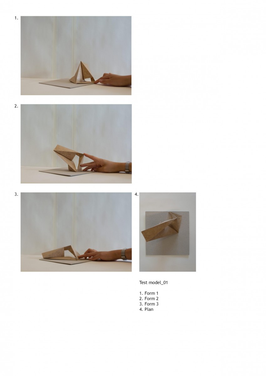
The first test was a planar study of space and allows a reading in plan and in section along a flat plane. When we bring in ideas of tectonics and thickness, we can easily extrude up and allow our architectural judgement to build on from this point.
The second test was a study in multiple dimensions and axis. Attempting to assign material qualities was a challenge and therefore this direction seemed like a viable path to further explore.
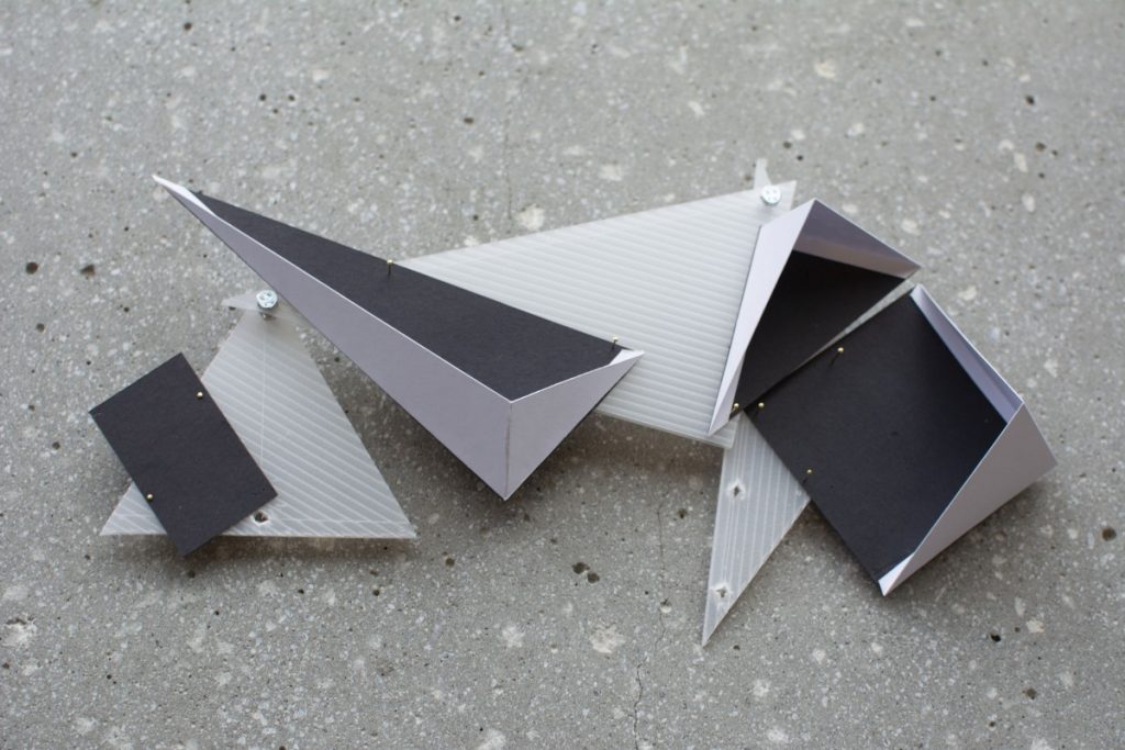
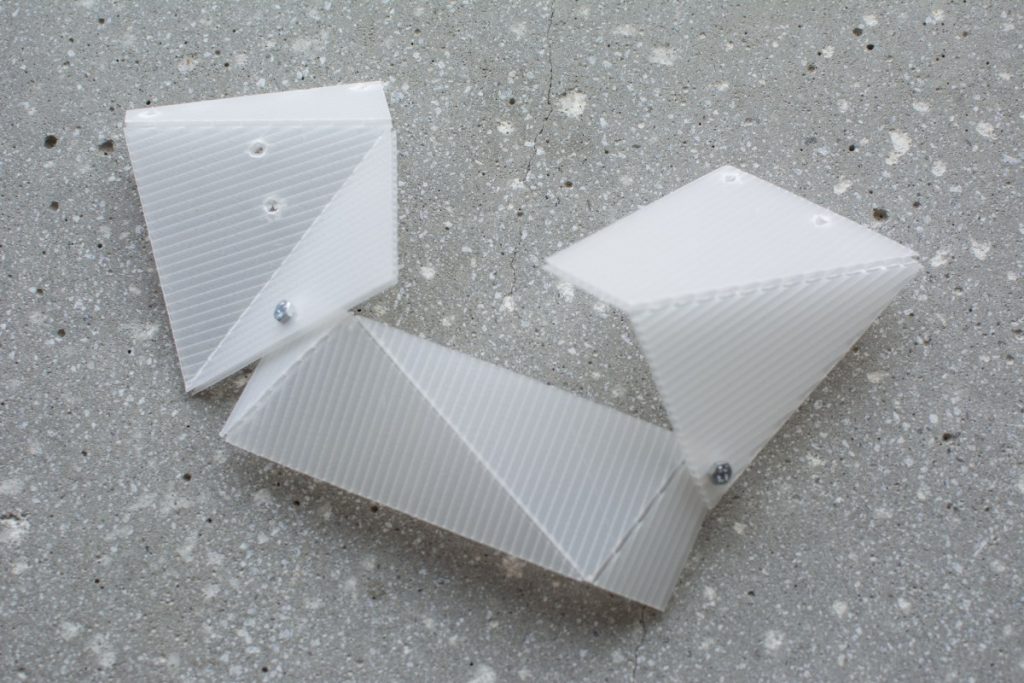
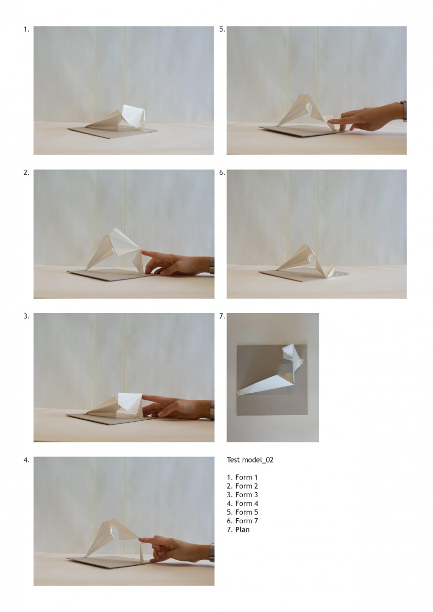
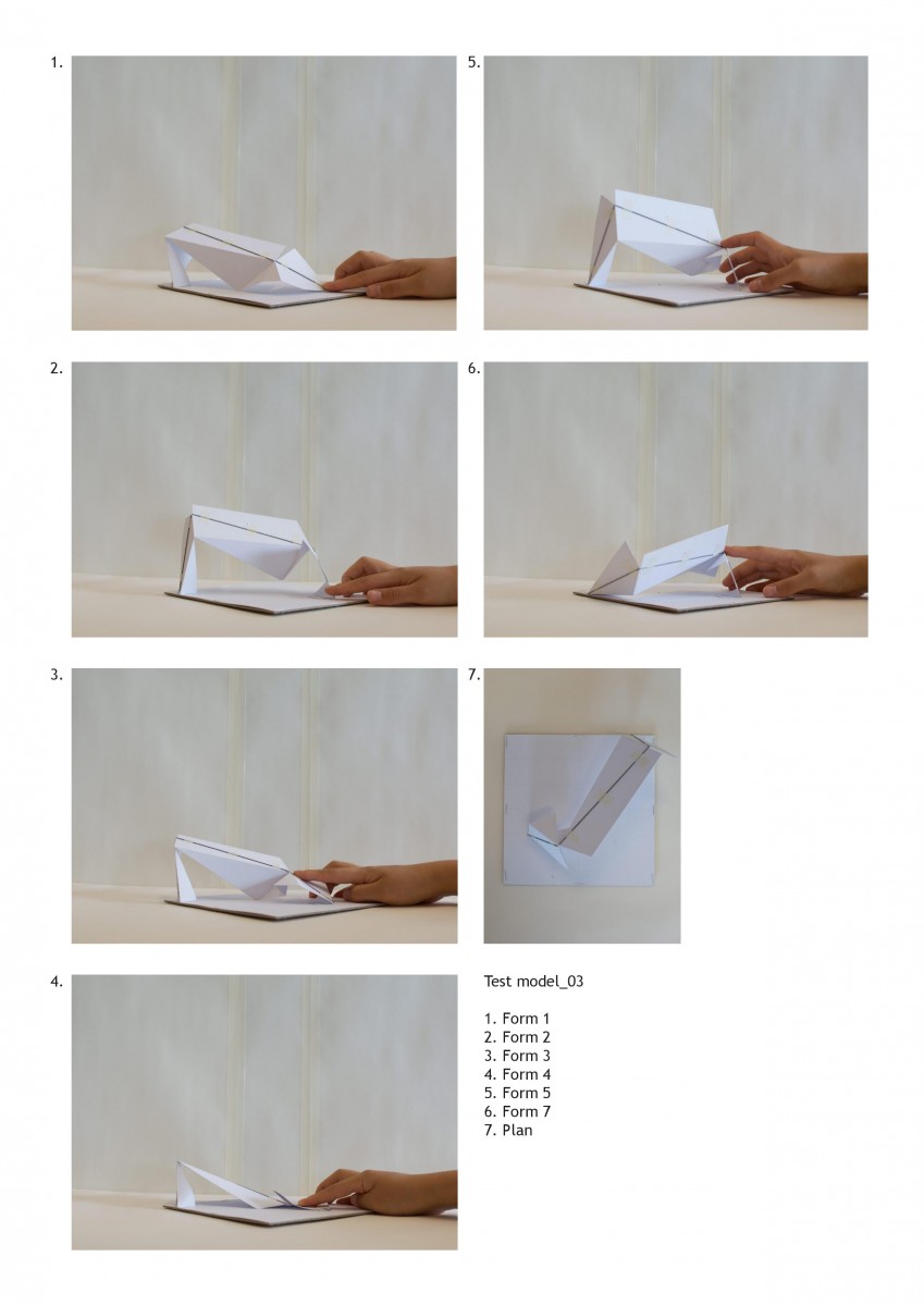
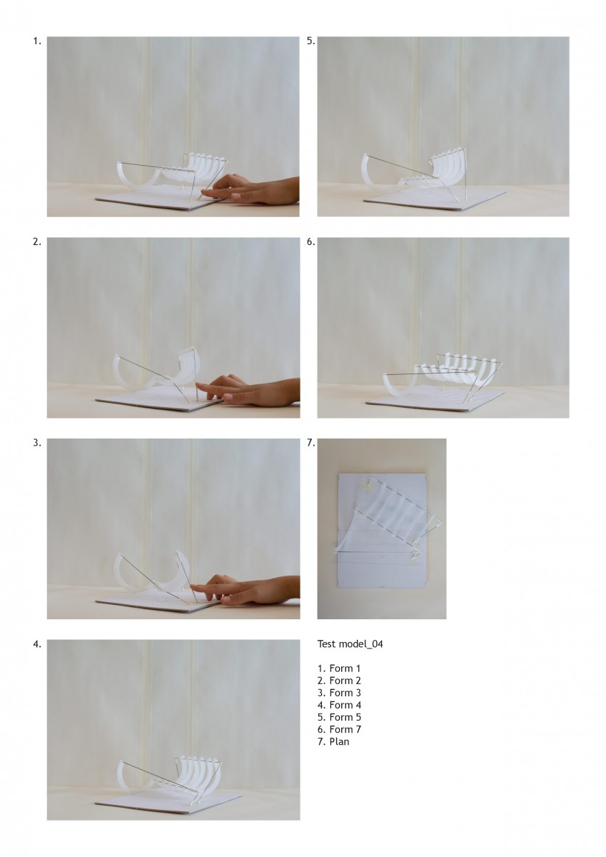
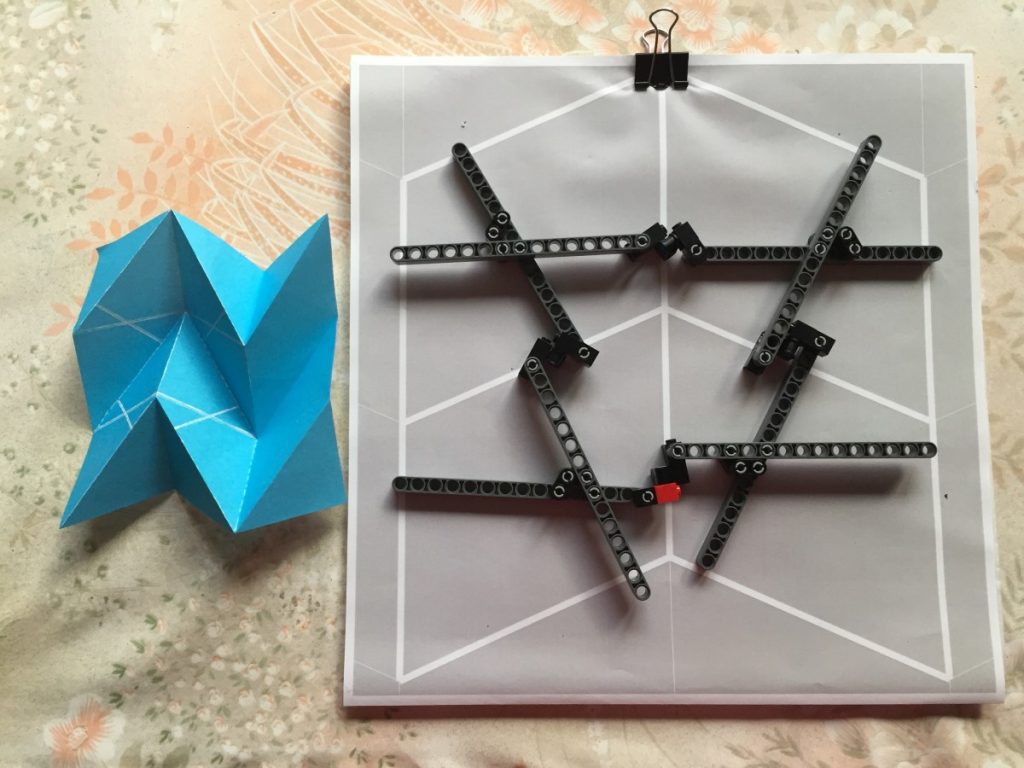
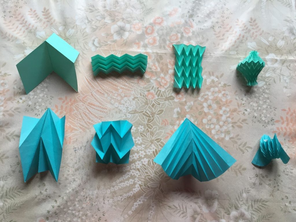
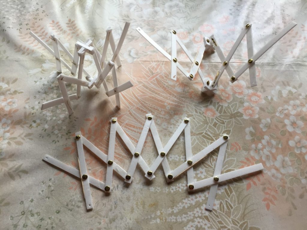
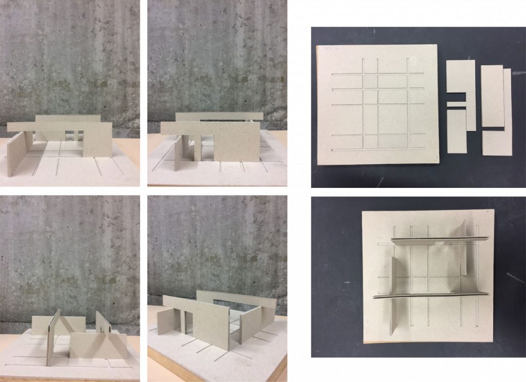
I decided to move the project forward by testing the idea of the four bar linkage across varying planes through simple paper models.
Each of these tests brought about questions of stability, connection points, anchor points, material qualities, thickness, how it meets the ground etc. Potential for the use of colour, thickness and additional elements that extend out from the four bars themselves can be observed. Although a prototype could be developed exploring a solution for such possibilities, I have not been able to push this study to that extent.
Project 3 and 4 has been a sort of research project into robotics, motorised movement and the exploration of what this other world of mobility can offer architecture. No end result as such was assigned throughout the process and I feel that that has allowed me to really understand the possibilities of these tools. I have hit many walls and found myself immersed in frustrations over what architectural meaning this project presents but overall, it has been incredibly fun and challenging taking an alternative approach to architectural design.
Master thesis final submission
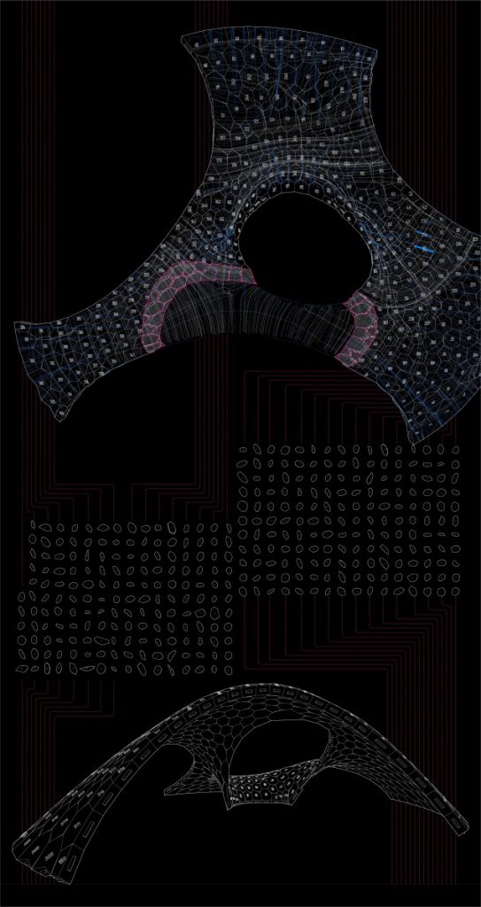
Compression-only based structures. Discrete element assemblies, double curved surfaces, shell structures, mesh tessellation and digital production
This master thesis is a research based project which explores compression-only based structures, covering such subtitles as – discrete element assemblies, double curved surfaces, shell structures, mesh tessellation of symmetrical and asymmetrical geometry together with digital production used for testing structural behavior of masonry structures. The background of the current research project was based on the works of Block Research Group. During this stage two different softwares were analyzed in comparison to each other (RhinoVault and Kangaroo2 for grasshopper) and the physical model of both structures was made. First experiments as compression-only based physical models were 3D printed from PLA and failed. Moving forward the further research methodology was developed – to start testing from simple structures – like arches and step by step by adding different variables explore the complex systems such as vaults, domes both single and double curved and finally – symmetry and asymmetry. This comprehensive analysis from the simplest element – arch to the most complicated sample – asymmetrical free form vault helped to deepen an understanding of behavior of such structures while testing the impact of thickness, curvature degree and curvature type, tessellation type and joints between the elements design. Furthermore, project covers digital production and fast prototyping techniques – 3D modelling, parametric modelling and 3D printing together with all challenges which can occur during translation of digital model into the physical model. Conclusions of the research project and implementation into the architectural field are proposed as analysis of adaptation to flat and uneven terrain, together with the analysis of different possible combinations of shell structures into the one whole system called mereology – in philosophy and mathematical logic, mereology is the study of parts and the wholes they form.
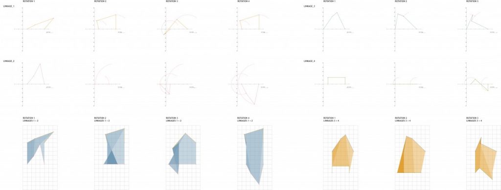
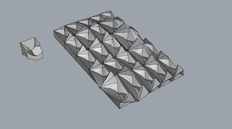
As we moved onto task 2, I started analysing forms of the linkages and combining two sets to test the spatial properties they exhibited.
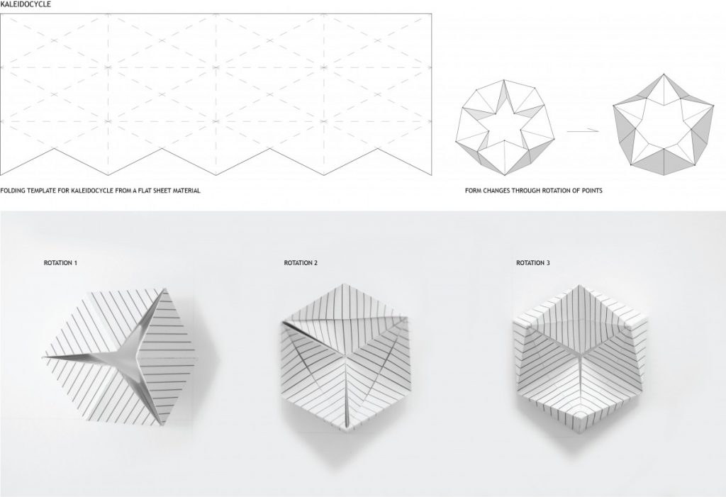
The rotation of the linkages needed to exhibit some form or motion and resulting change that would offer a variation in form and surface and space, as in the previous study of the kaleidocycle.
The servo was mounted to a clear acrylic frame and I began to run tests of forms using the basic principle of the four bar linkage.
As observed from the tests above, the spatial study extended only to planar elements. I began incorporating rotation and folds to allow for movement in 3 dimensions and multiple axis for each linkage. Both sets of studies provide grounds for further exploration but I will need to be more intentional in the variation of parameters of the subject.
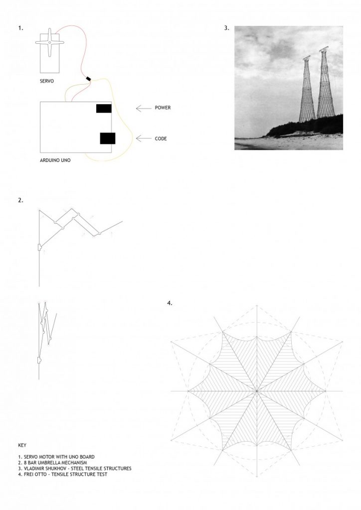
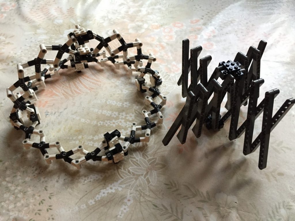
Project 04 saw a move to material prototyping and developing a methodology for building three dimensional forms. I looked into Frei Ottos fabric tensile structures as well as engineer Vladimir Shukhovs steel tensile structures as precedent.
Keeping the automated robotic theme running I also decided to incorporate a servo motor into my design process. This brought a moving element to the prototyping and prompted the research into the umbrella mechanism and three/ four point linkages.
I also explored the Kaleidocycle (flexagon) which are models of linked tetrahedra which turn through their centres. I wanted to incorporate these methods for materials that, through their connection, could change form and produce multiple spatial environments.
‘Flat pieces cost one dollar, single curvature pieces cost two dollars, double curvature pieces cost ten dollars. The good thing about the computer is that it allows you to keep a close control over the geometry and the budget.’ – F. Gehry
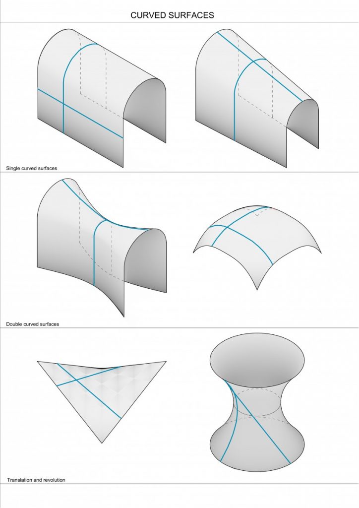
Single Curved Surface – only one of two curves is actually curved, making this shape developable (in mathematics, a developable surface is a smooth surcafe with zero Gaussian curvature, meaning it could be flattened on plane without distortion).
Double Curved Surface – non-developable surface. Saddle shell has compressive stresses along the convex curvature and tensile stresses along the concave curvature. In the 2nd dome example when both dimensions are curving in the same direction meaning that the dome is under compression everywhere.
Hyperbolic paraboloid is a double curved shape which can be created with straight lines, yet non-developable. Both hyperbolic and conical paraboloids has excellent tensile and compressive properties and can be built with straight members, that making the production relatively cheap and easy.
Source: The Function of Form by Farshid Moussavi
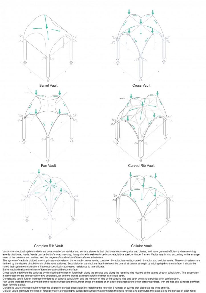
Vaults are structural system which are composed of curved ribs and surface elements that distribute loads along ribs and planes, and have greatest efficiency when resisting evenly distributed loads. Vaults vary in kind according to the arrangement of the columns and arches, and the degree of subdivision of the surfaces in between.
Can be divided into 6 primary subsystems defined by the degree of subdivision of the vault surfaces.
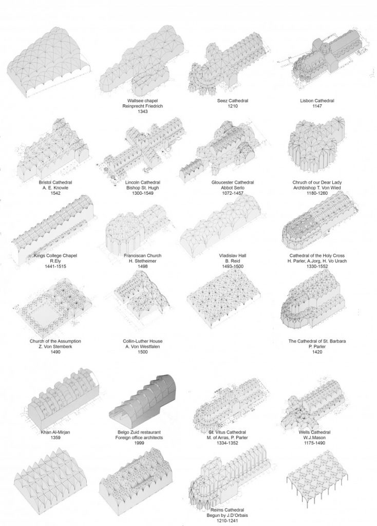
There are many great examples of vault architecture built in the mid-centuries, mostly used for sacral building. For the most of these examples building process took even several centuries. Most of them were arranged as a tessellation of the same symmetrical element, although even then some elements in the building system were trying to break the symmetry.
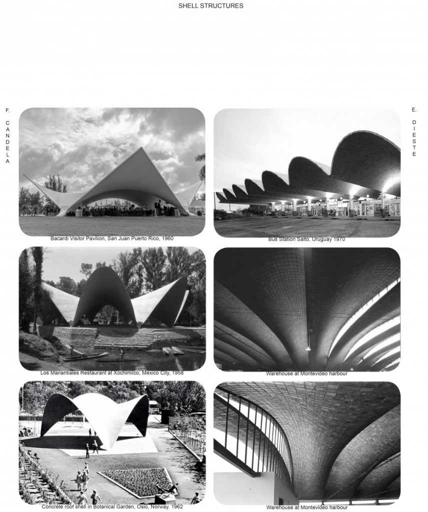
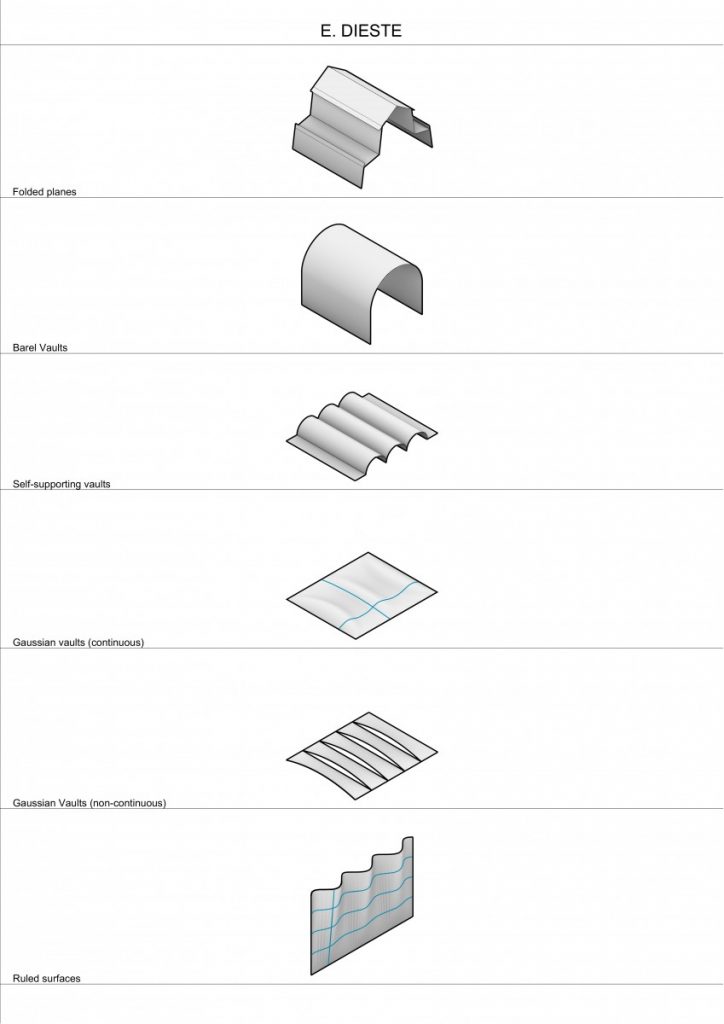
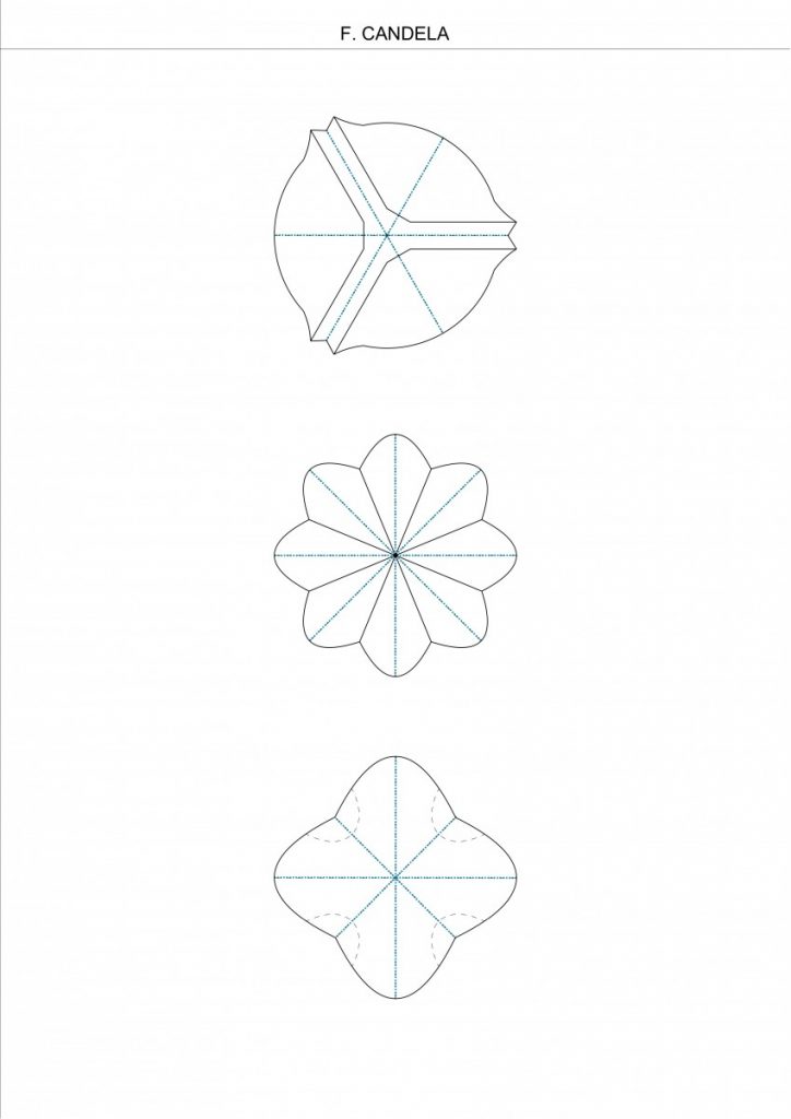
At the 20 century there were two architects – engineers working with curved surfaces – Felix Candela – concrete single surface shells and Eladio Dieste – mainly exploring the masonry structures.
In the works of E. Dieste we can find the same repetition of symmetrical elements, thus making the production easier, cheaper and faster.
In the F. Candela’s approach we can find radian symmetry and repetition of the same element.
Same as vaults, shells are composed of surfaces that distribute loads in plane and have the greatest efficiency when resisting evenly distributed loads.
Going forward to present:
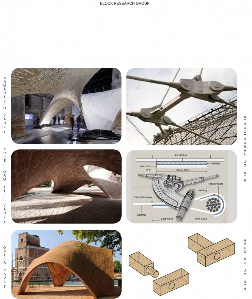
Block Research Group (BRG) for the past 10 years are researching both shell and masonry structures of double curved surfaces. Due to the computational and digital fabrication tools being able to break the symmetry and work with free form structures.
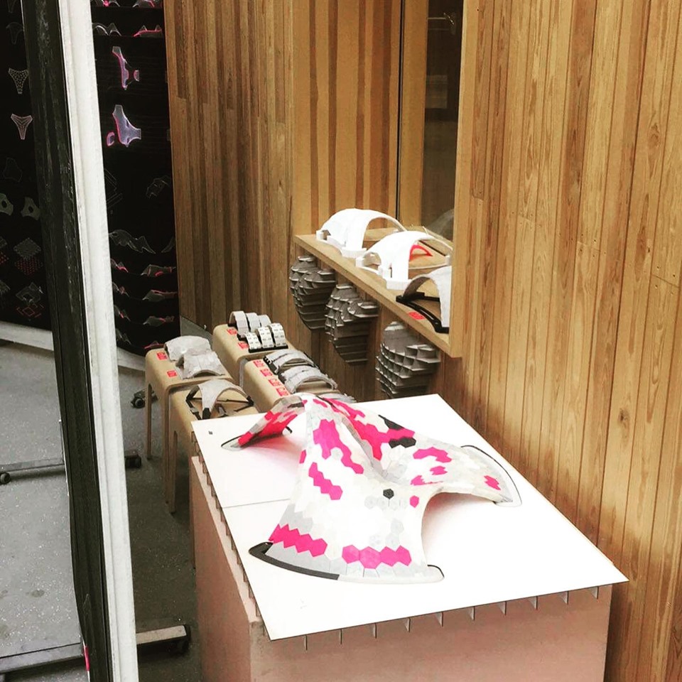
In 2016 at Venice Biennale presenting the Armadillo vault project, which was built from flat stone pieces, without any glue/cement, meaning that structure was compression-only based.
There I want to discuss two different types of joints – the structural and the holding or orientational ones (such as mortise tenon joint). Structural joints – such as found in Frei Otto buildings or Japanese temples are the elements which basically holds all the structure and loads, meaning that without them it is destabilized and without equilibrium, meaning that they are extremely expensive and complex.
When the structure is in equillibrium itself – meaning it is stable by itself, the joint ensures the stability of it according to the external factors, such as wind, earthquake, explosions, hurricanes. For the long-term structures such joints was cement or grooves, sometimes both of them.
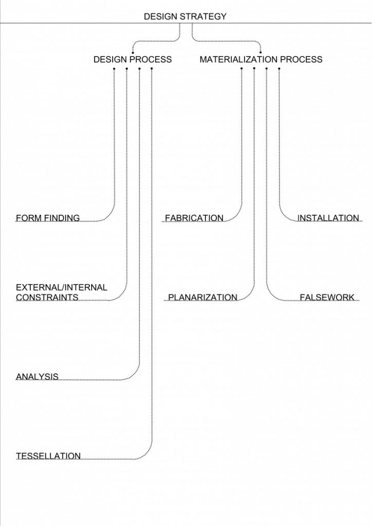
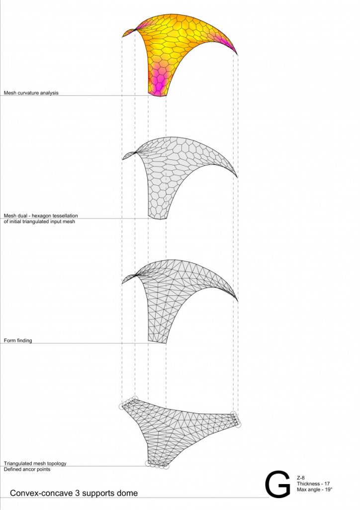
The primary approach for the design strategy in this project was based on BRG research methodology, where it consisted of two main stages – design and materialization. Design consisting of form finding, which can be influenced by external or internal constraints (such as – terrain, sunlight, the size and width with height or openings defined by the architectural program, function, vistas, flows (as movement).
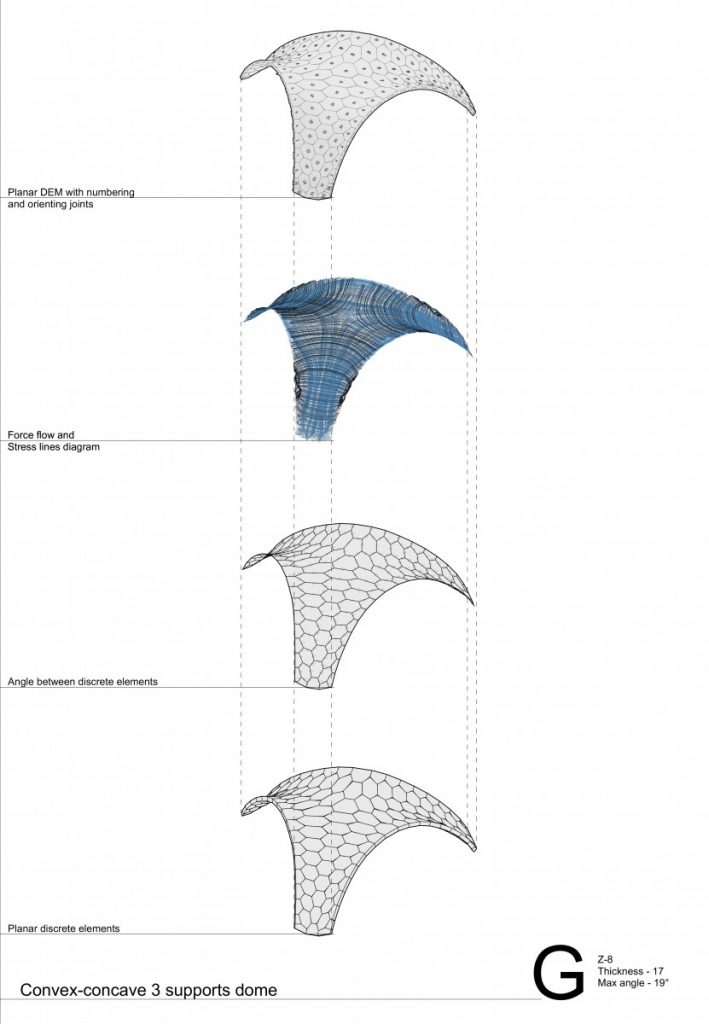
And structural analysis with tessellation of a shell.
Production is mainly consisting of two main parts – fabrication and installation.
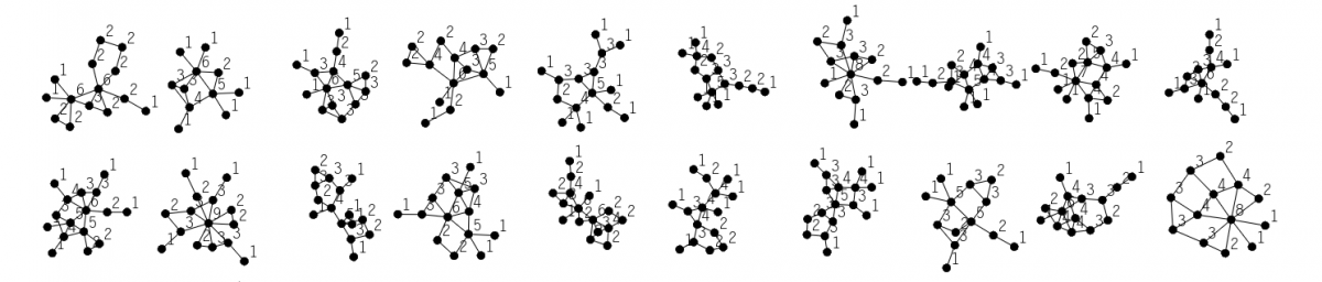
During the background research I was working with two different plugins – Kangaroo2 by D. Piker for grasshopper and RhinoVAULT by M. Rippmann for Rhino5, the detailed workflow comparison of both of them can be found in the image above.
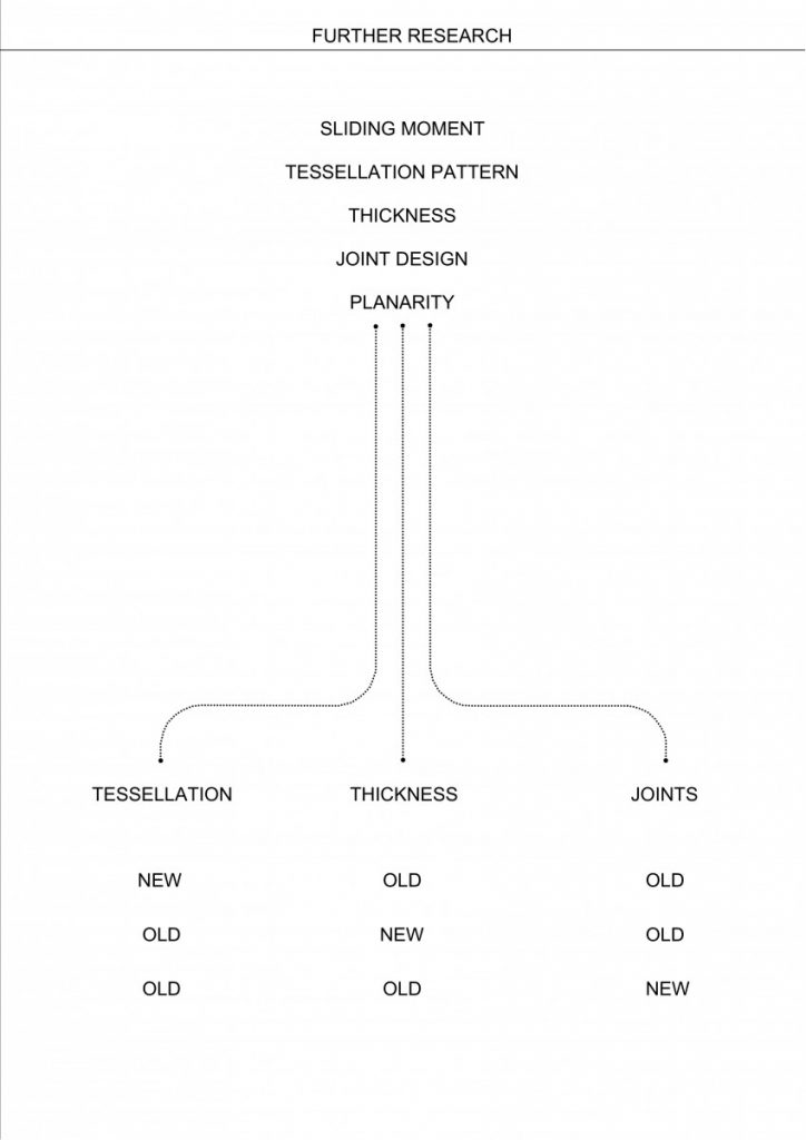
As both experiments with the structures made with Kangaroo2 and RhinoVAULT failed I was able to formulate further research development, defining these main parameters:
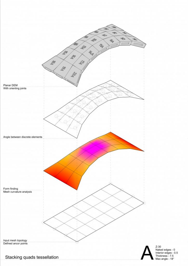
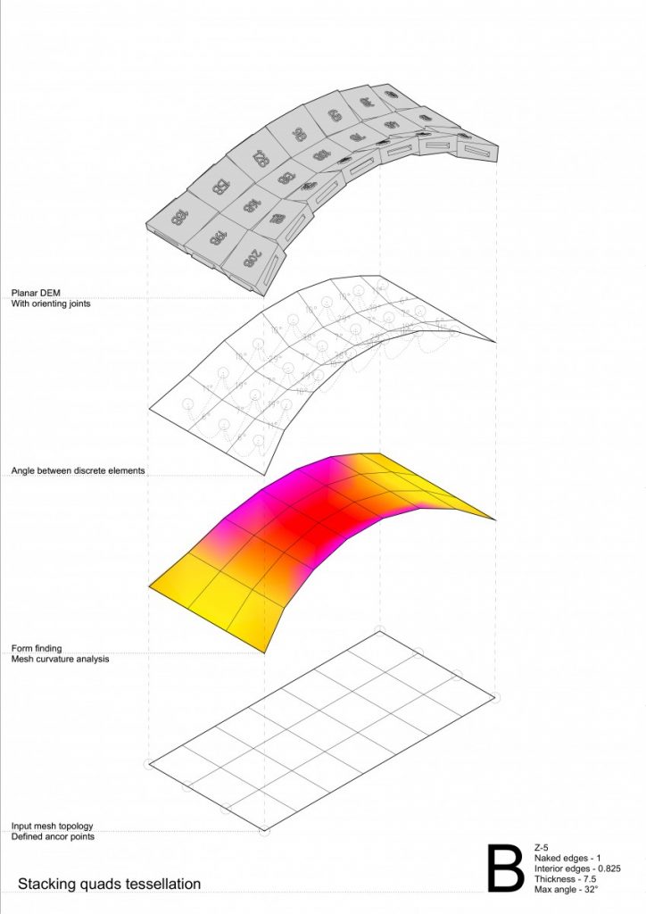
Sliding moment or in other words – angle between two elements;
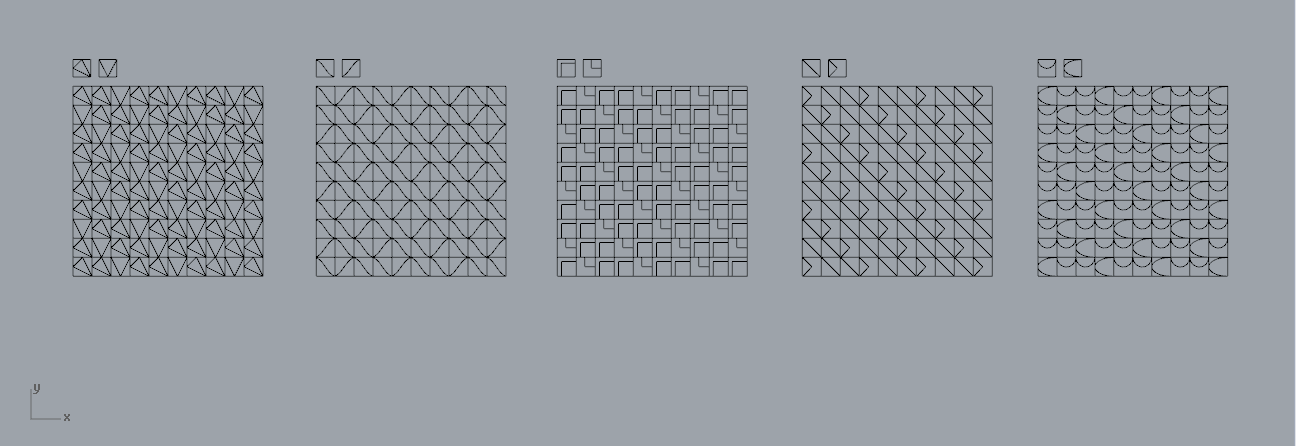
Tessellation pattern;
Thickness of elements;
Orientational joint design;
Planarity of elements (meaning that touching surface is reduced by element’s shift during the planarization);
And decided to change 1 thing at the time.
… And experiment failed again.
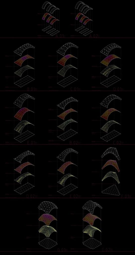
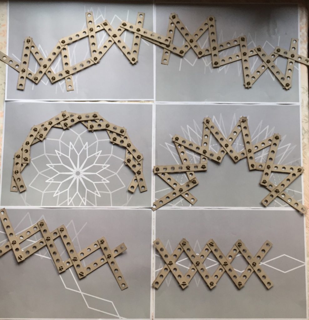
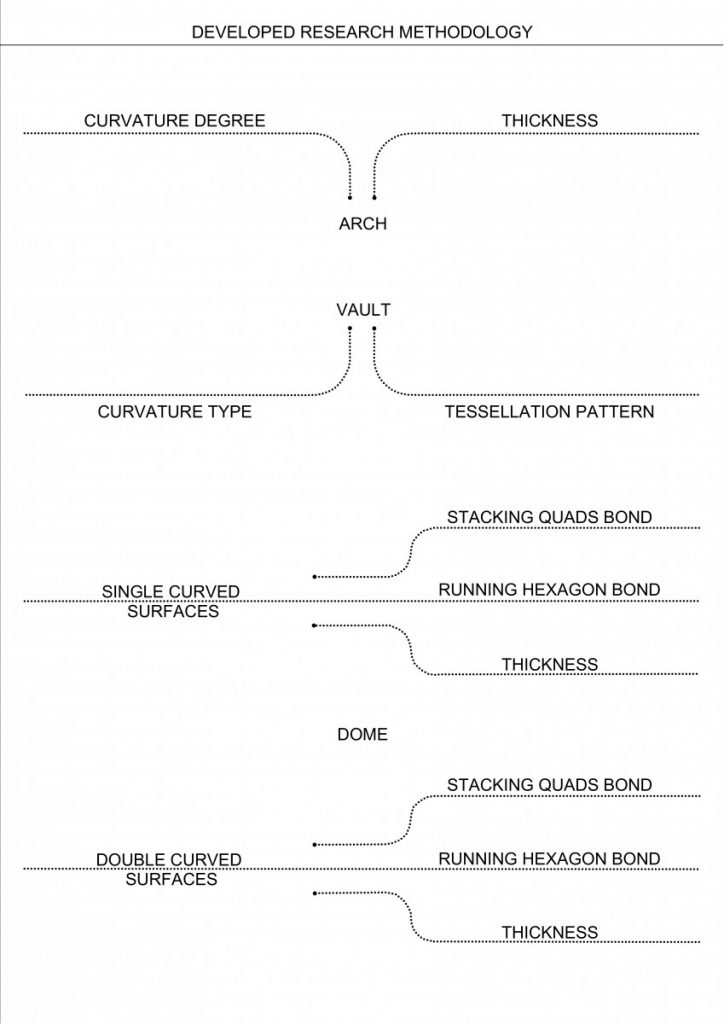
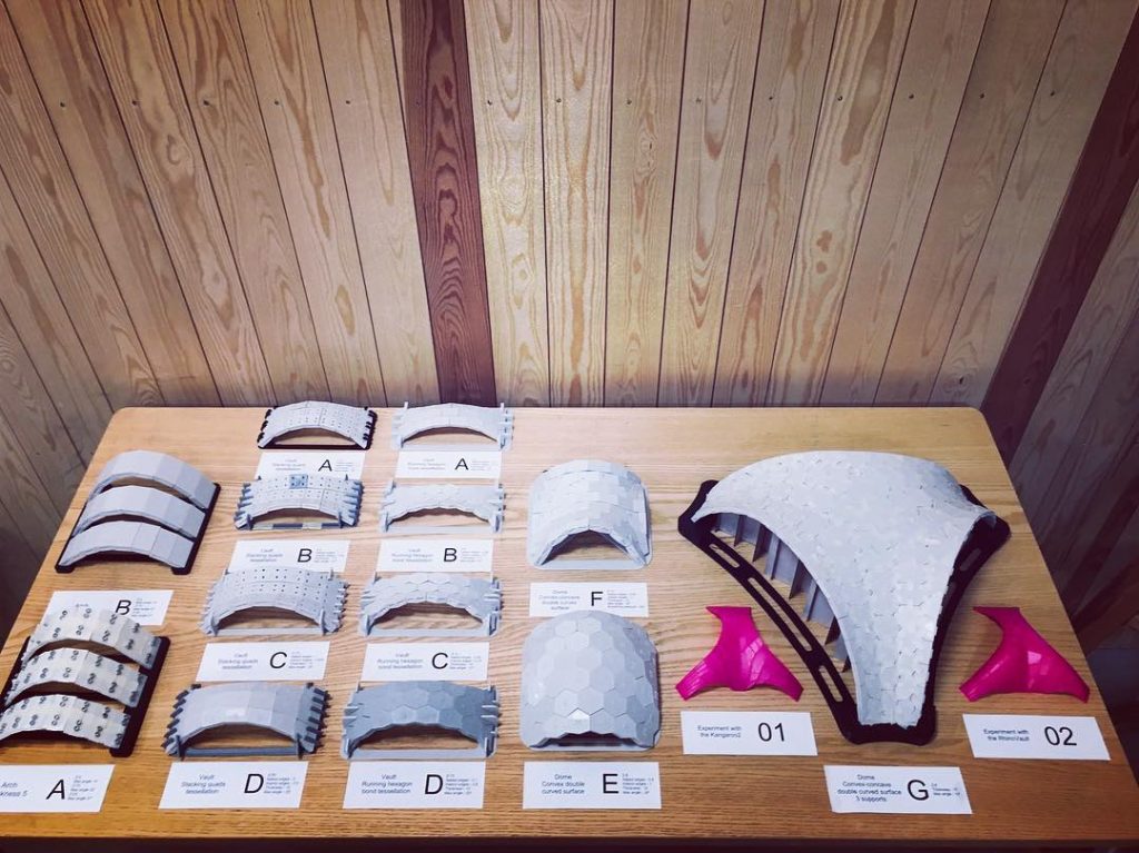
All that helped me to develop my own research methodology – making things clear – to start from simple things, such as arches, where I could test the impact of curvature degree and thickness.
And gladly, this time that worked.
Where I could make clear conclusion about the matter of thickness not so much of a curvature degree.
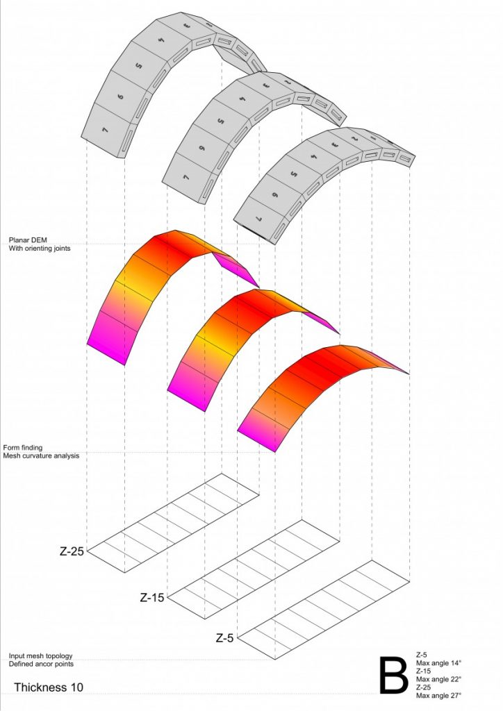
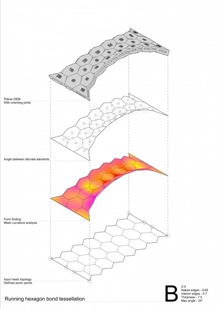
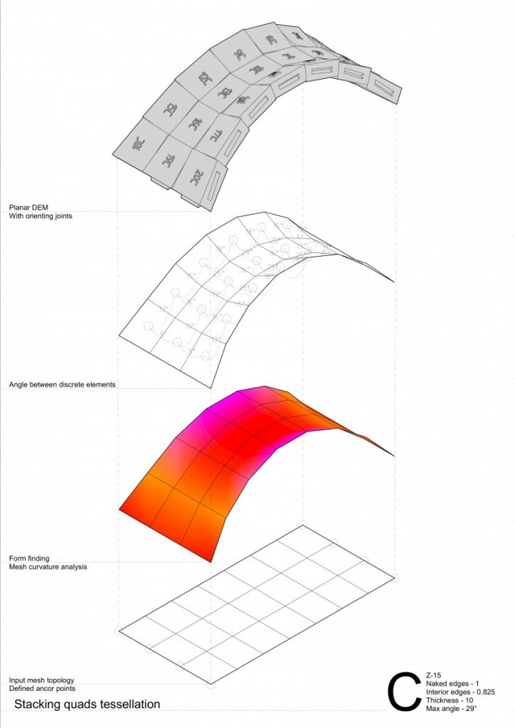
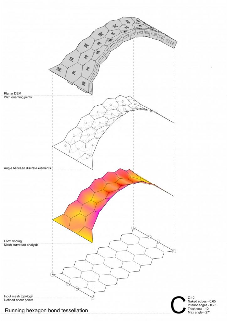
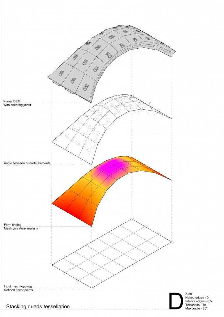
Moving forward to add two new variables – curvature type and tessellation pattern testing in it on more complex geometry – vaults.
The conclusions made from these series of experiments were:
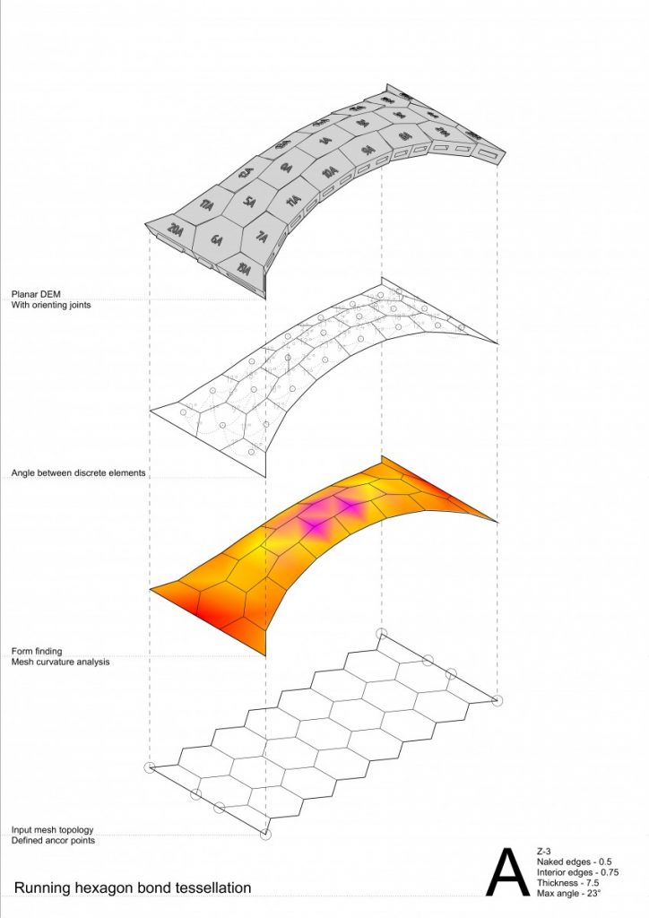
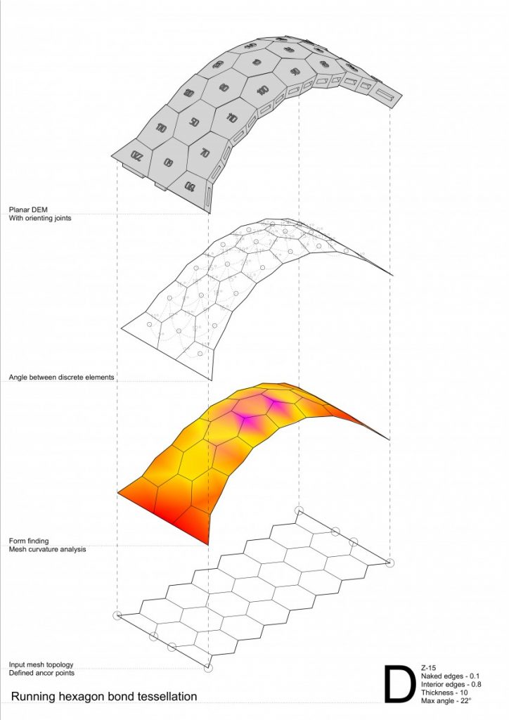
Running hexagon tessellation has greater behavior of a self interlocking elements;
In convex curvature stripes tend to separate from each other by arches both in stacking quads and running hexagon bond tessellation;
While in concave – convex curvature by forces coming from the side stripes the problem disappears;
Higher degree of curvature or in other words angle between elements has an impact of greater behavior of a compression-only based structures;
Hexagon tessellation in concave curvature tends to higher distortion thus becoming more similar to a quad. If the concave curvature would be even higher – hexagon with tends to have two opposite corners going inside the 2D geometry (reminding a ribbon shape);
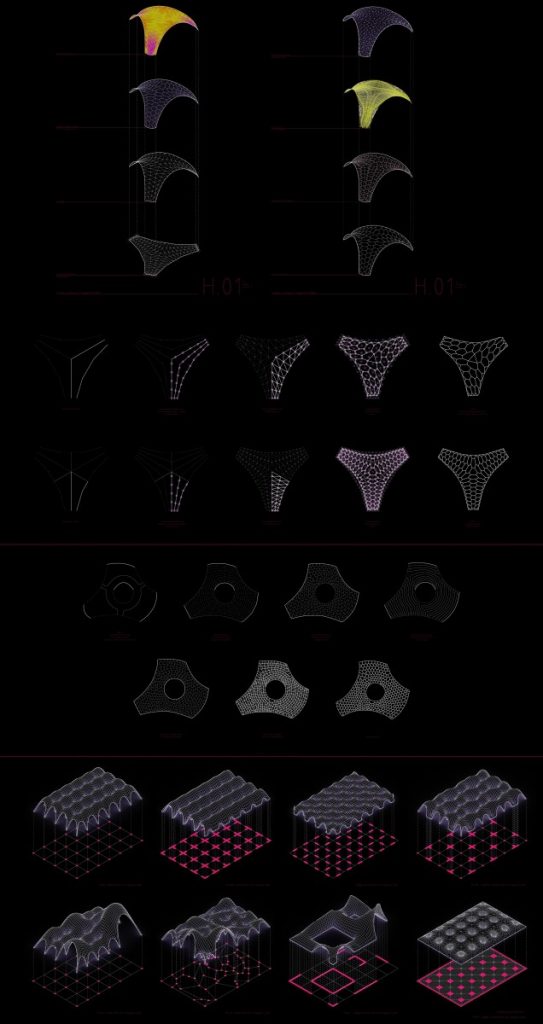
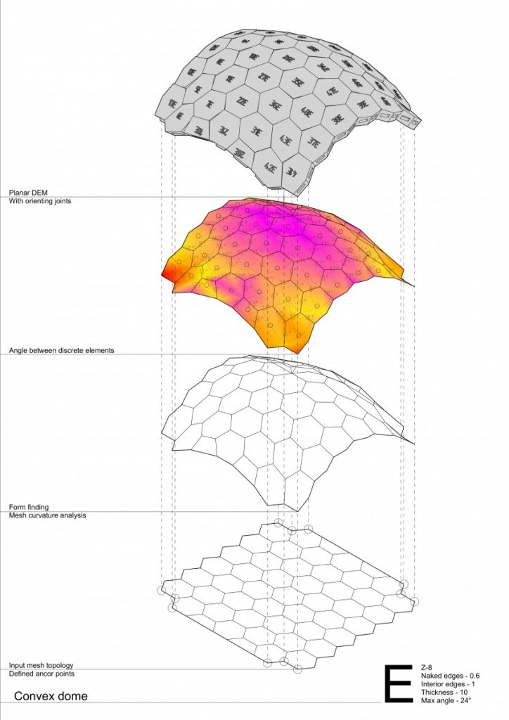
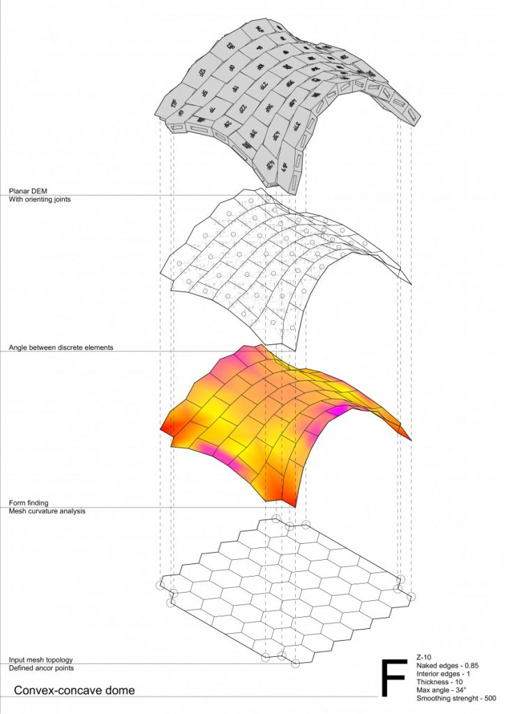
And to move even more forward – testing single and double curvature with variables such as tessellation pattern and thickness on even more complex geometry – domes.
In convex running hexagon tessellation the self interlocking behavior of a pattern feels even stronger, the structure is extremely stable, comparing to all other experimental models.
While convex-concave stripes tend to separate themselves into individual arches, although the structure is stable and distribute even loads very well, able to carry 20x of it’s self weight (doesn’t work for a point loads at all…)
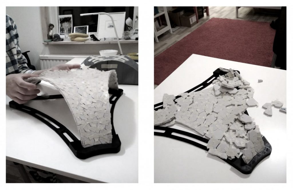
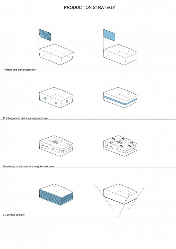
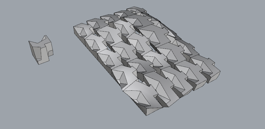
As the production strategy in this project is equally or even more important than a design process I would go through key points:
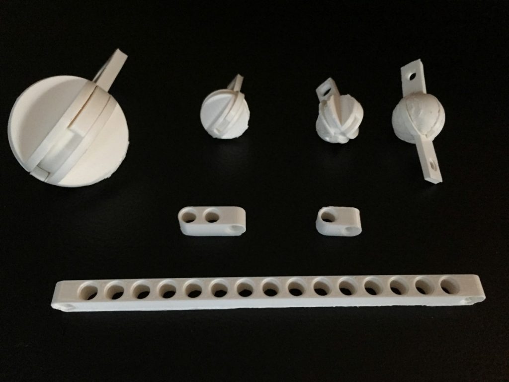
Twisting and planar geometry – rapid and easy production is impossible having twisting geometry, therefore discrete elements needs to be planar and 3D printable or easy to cut;
As from the previous research it was clearly seen that points loads with the radius of 2mm and the height of 1mm are not enough for alignment between elements and due to the sliding moment in between them causing the collapse of the entire structure they were improved to linear alignment joints;
All elements are numbered, but this part could be improved by defining the neighboring elements’ numbers, thus making the assembly possible without any additional instruction;
As for the 3D printing strategy – challenges found there consist of tolerances, shrinkage and expansion of the material, so called elephant’s foot at the bottom of the element – all these can be solved by testing, trying and experimenting with your machine. As for the elephant’s foot – chamfering the bottom edges of the elements worked pretty well.
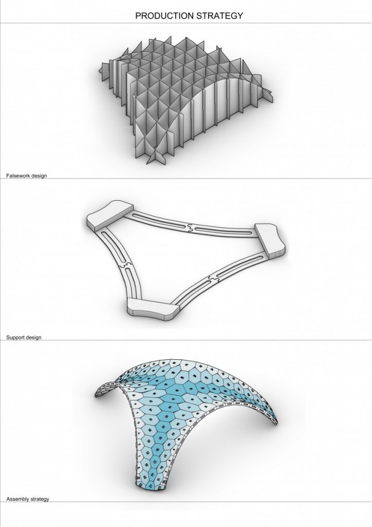
Falsework is made using Bowerbird plugin for grasshopper making it fast and easy both for the design and production.
Supports are modeled manually, but also evolving during the whole research – tolerances, joining separate parts of support structure, reducing mass for faster production, design etc.
Assembly strategy – working with smaller structures helper to very easily and intuitively understand the principle of going by stripes/arches and from medial spine while assembling the structure.
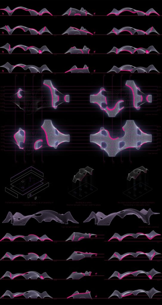
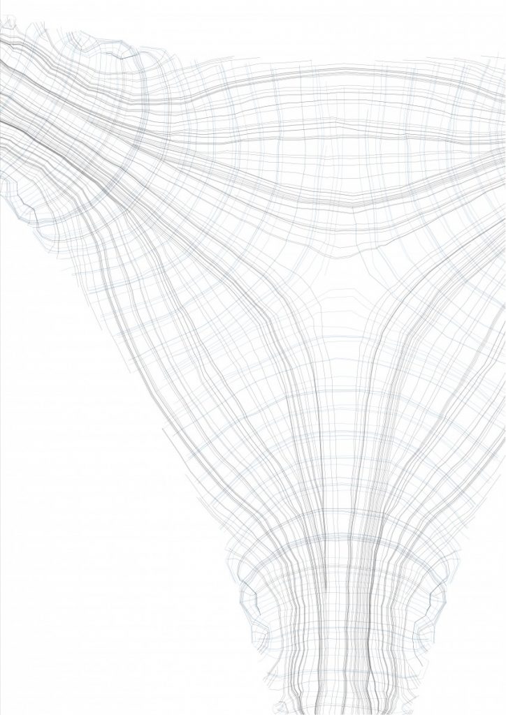
Force flow (black) and perpendicular stress lines (blue) on the shell structure.
To sum everything up, my objectives during this master thesis project is to develop a deeper understanding in the structural behavior of free form structures based on the scientific research method – learning by observation – meaning that infinitely strong digital clay model in digital environment should be tested as a physical model.
Be able to work with complex systems, investigate the possibility of adaptivity of shell structures to different terrain conditions, therefore the shift between the bespoke design and the universal design model.
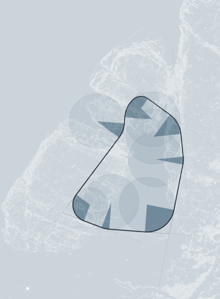
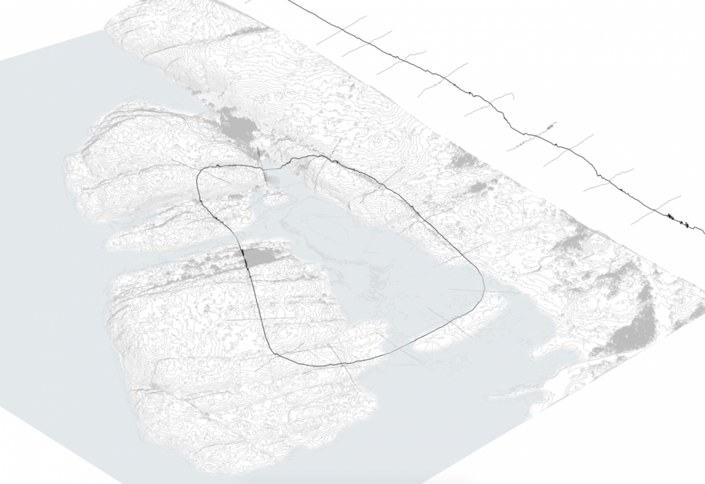
Since the last post, I back tracked a little bit to refine and rationalise the ‘loop’ path. By analysing the steepness of this region in more detail, ridges in the rock are highlighted. I then traced these ridges and extended them to meet the next one, which formed a boundary. I took the inner region of these lines, and gave a fillet at the intersections. This loop is now a series of straight segments and arcs.
Rationalising the path | Plan of Dödviken
A benefit of building along ridges along the site is that it lowers the highest point along the route. This means that the path, which is at the average height of all the points it crosses, is lower. The bridges are a more reasonable height above the water, and the tunnels are at a more reasonable depth within the ground.
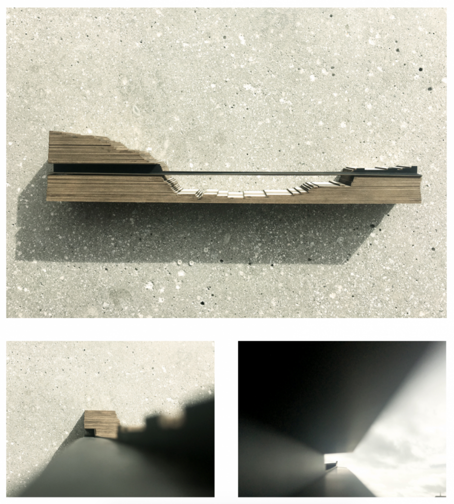
I would like to begin to analyse segments along the route for their materiality and geometry, both along the path and perpendicular to it. This can begin to form rules and inform the program of the camp.
Finally, this model shows a segment along the route where the path cuts through the rock as a tunnel, crosses over the water as a bridge, and continues over the ground as a path.
The robot allows for direct feedback for the design strategy proposal. In oder to fully apply this method of working I formulated a strategy for the summer camp as an initial system of production, construction and form to allow for freedom in testing.
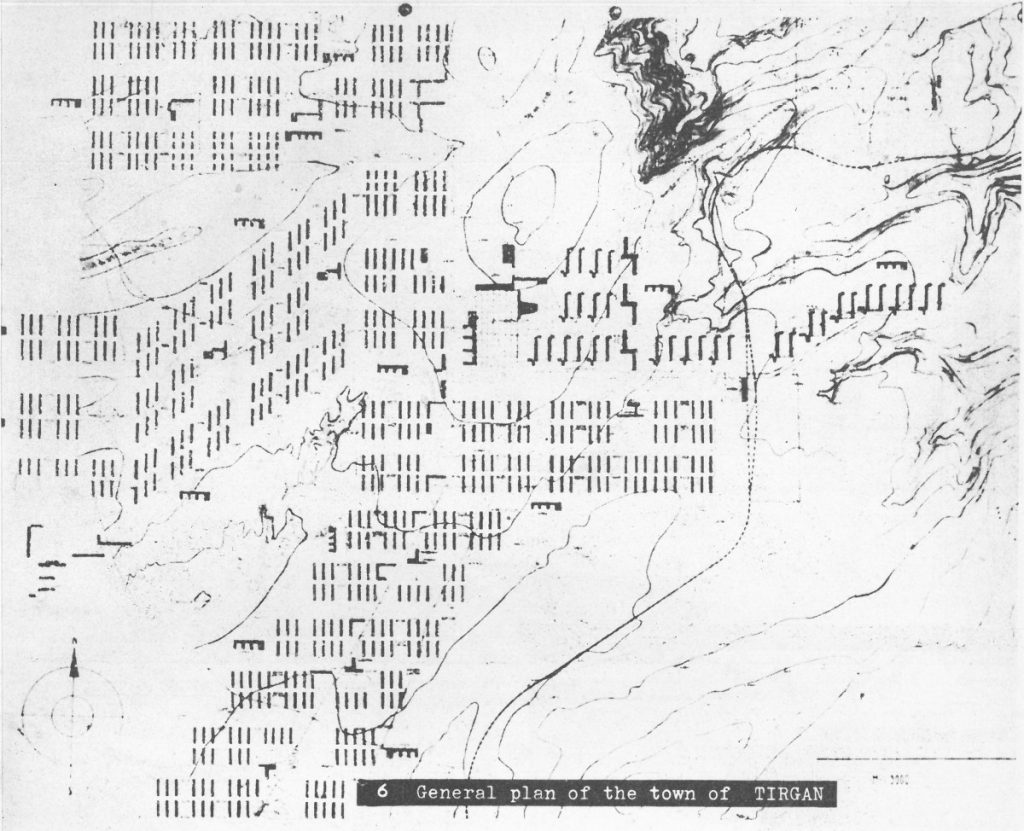
I took the soviet architectural town planning in 1930 by E. May as precedent. The linear markings on the site appears to respond to the context yet also offer an abstract notation of the program of development. The summer camp proposal for Malmon will be about setting up a grid that will be the groundwork for precast members that can easily be assembled and disassembled. Concepts of sustainability and impermanence are suggested.
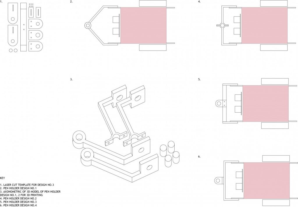
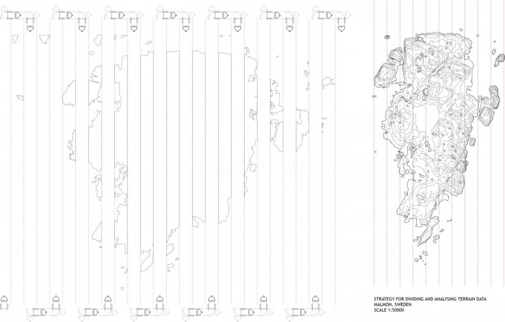
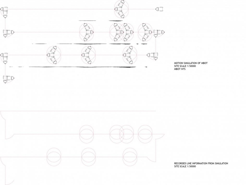
To obtain an output from the robot I 3D printed a set of arms/ pen holders to obtain a line drawing from the site analysis. While the robot scans the site, It would produce a line drawing as a data output. The implementation was dictated by the robots sensors, size and my coding capabilities. I did not achieve an outcome that could be presented or represented the idea. For the final task in this project I will work towards focusing on what data I want as an output and a much simpler application of the robots abilities.
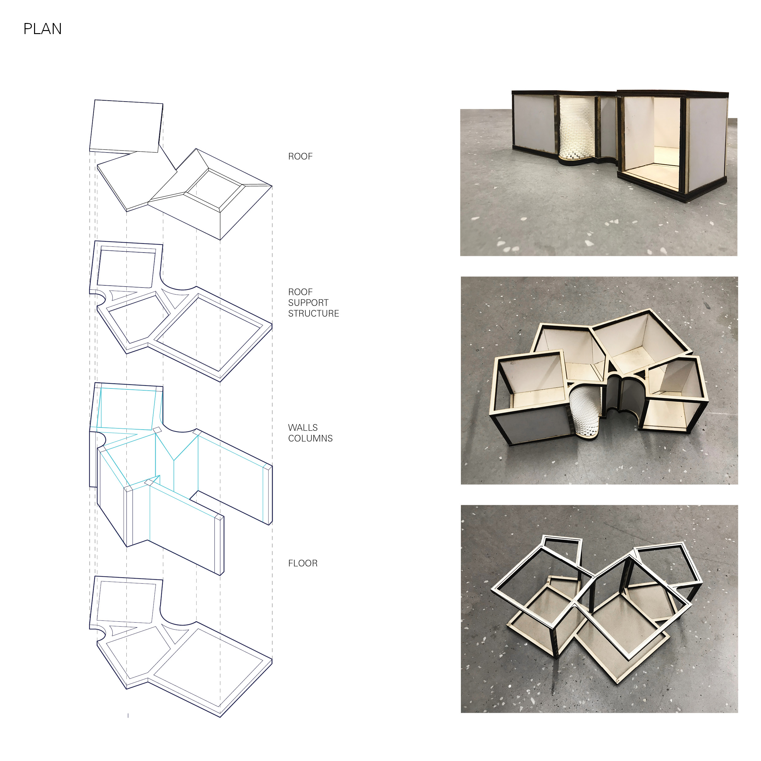
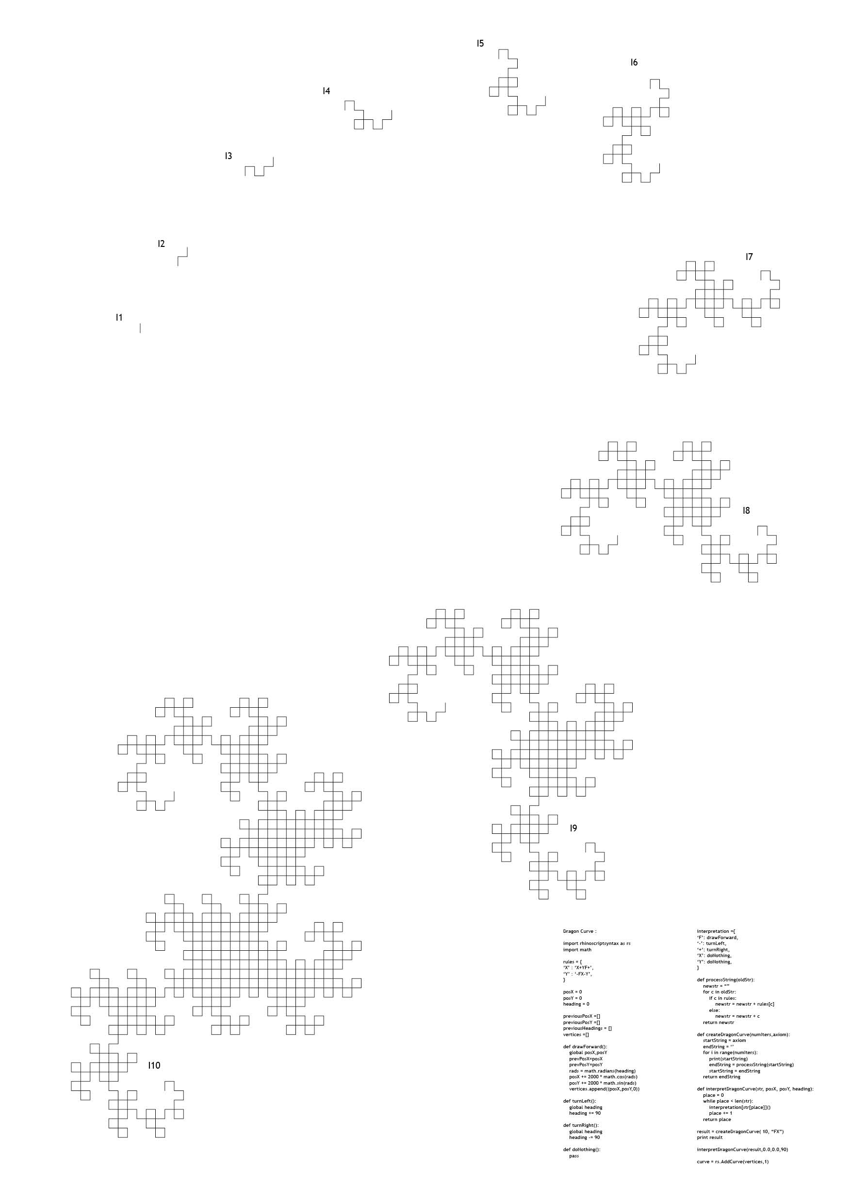
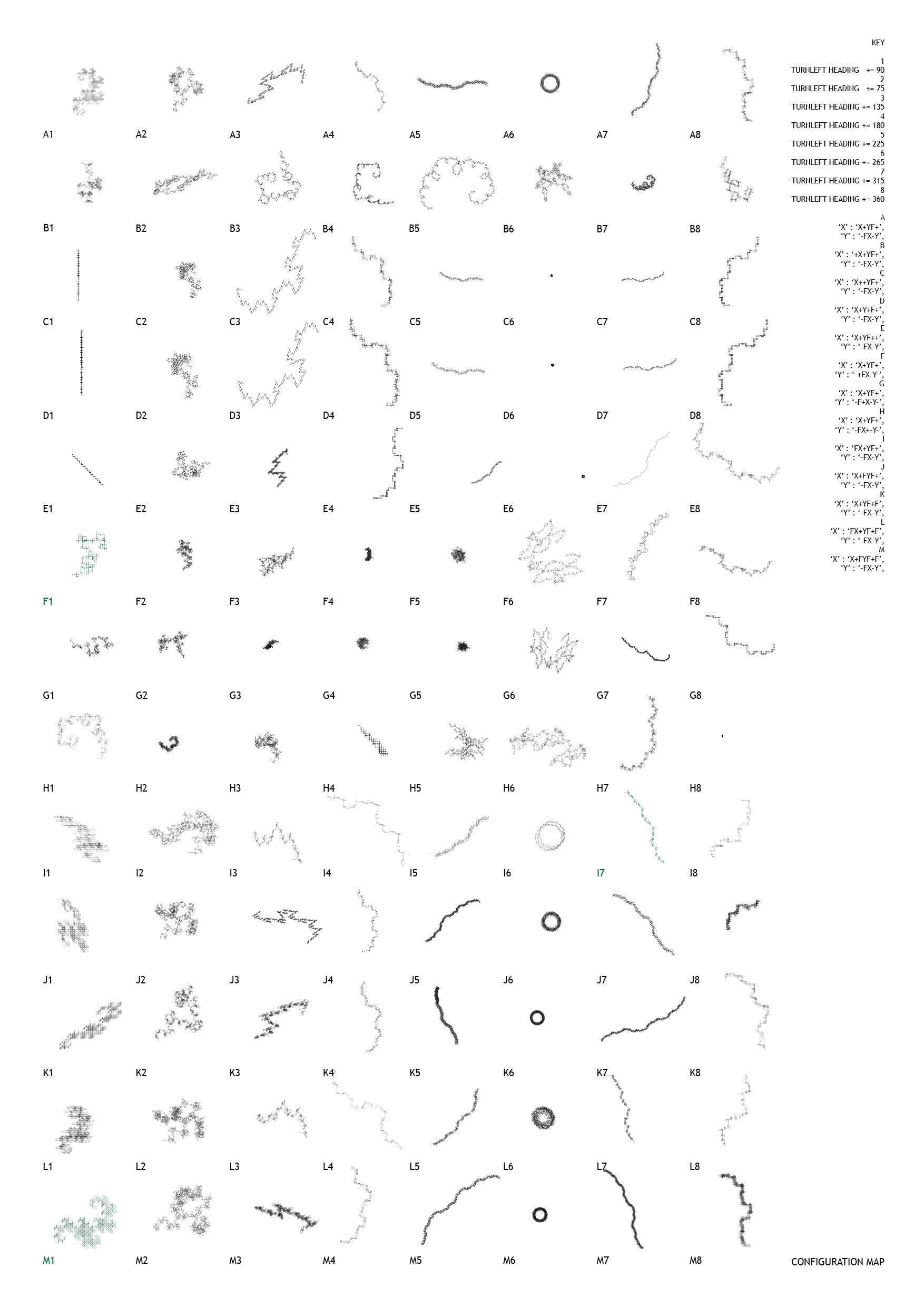
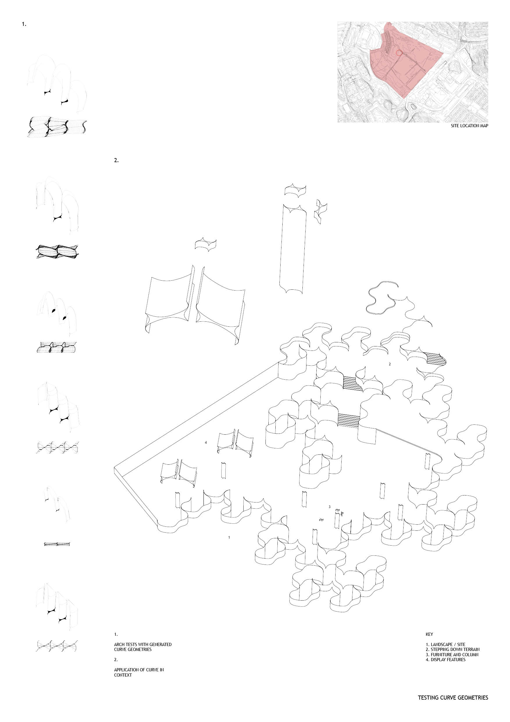
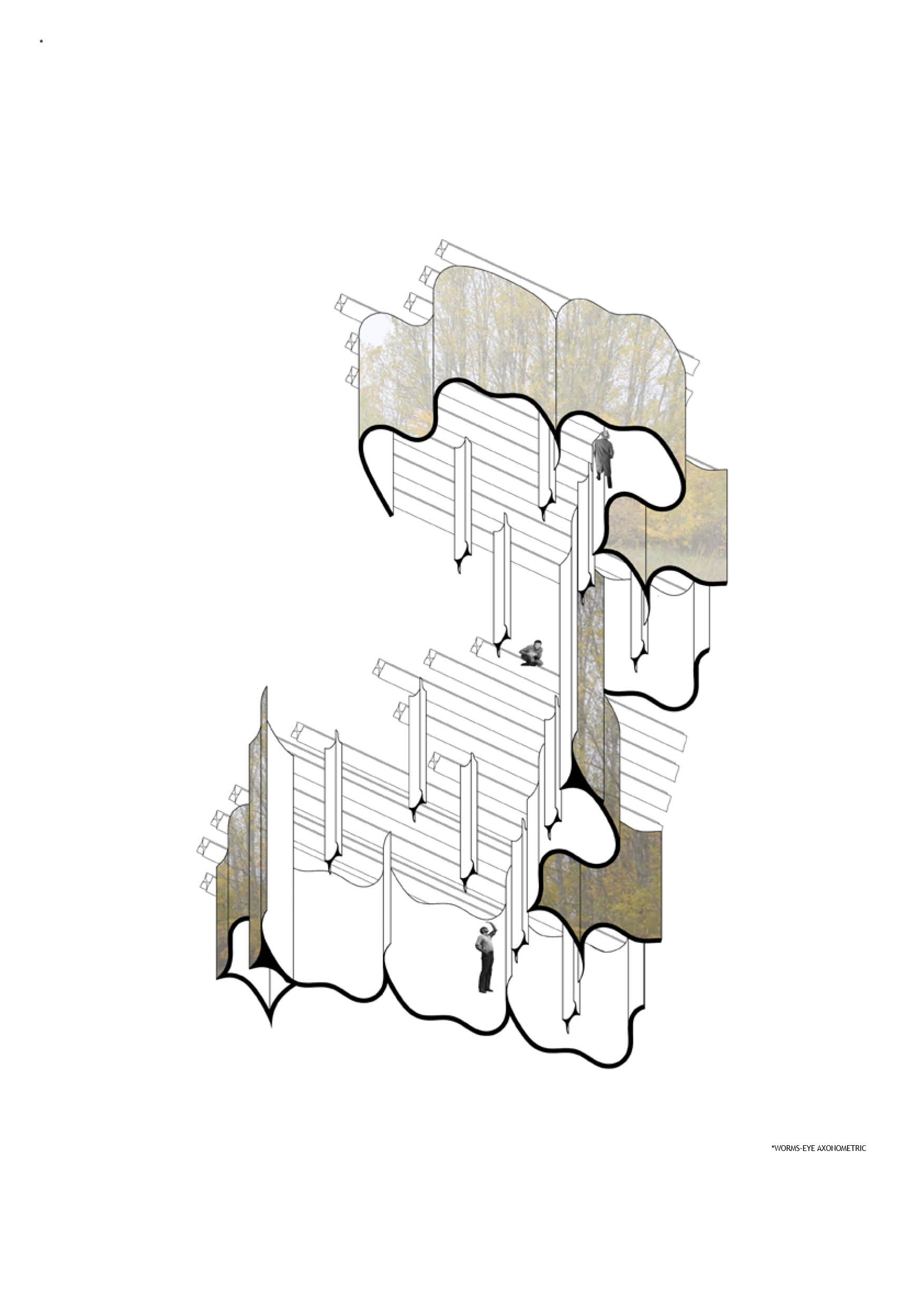
Drawing from the research and testing throughout project_01 and _02, I began to compile and implement the system I created in order to give architectural form to the space filling curve that is the dragon curve. The path and control points of the test M1 from project one inform the grid along which both the walls and roof structure are set, thereby enforcing a direct correlation between section and plan. Altering parameters such as thickness, scale and spacing of the walls and roof, with respect to desired lighting, movement, material etc. can easily be navigated as the structure and form are resolved thanks to the connection in plan and section