P4.T3+Final Presentation.More?

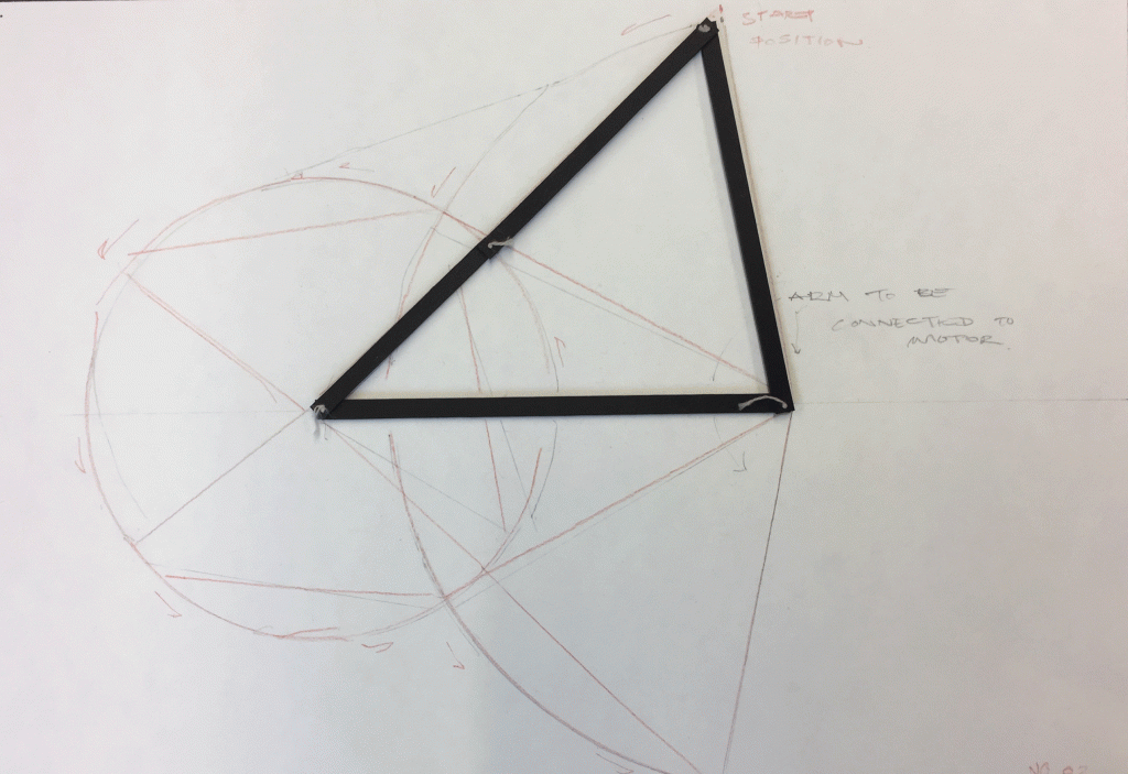
In the previous exploration we observed the spatial and form giving possibilities of the four bar linkage when combined with the servo motor.

The first test was a planar study of space and allows a reading in plan and in section along a flat plane. When we bring in ideas of tectonics and thickness, we can easily extrude up and allow our architectural judgement to build on from this point.
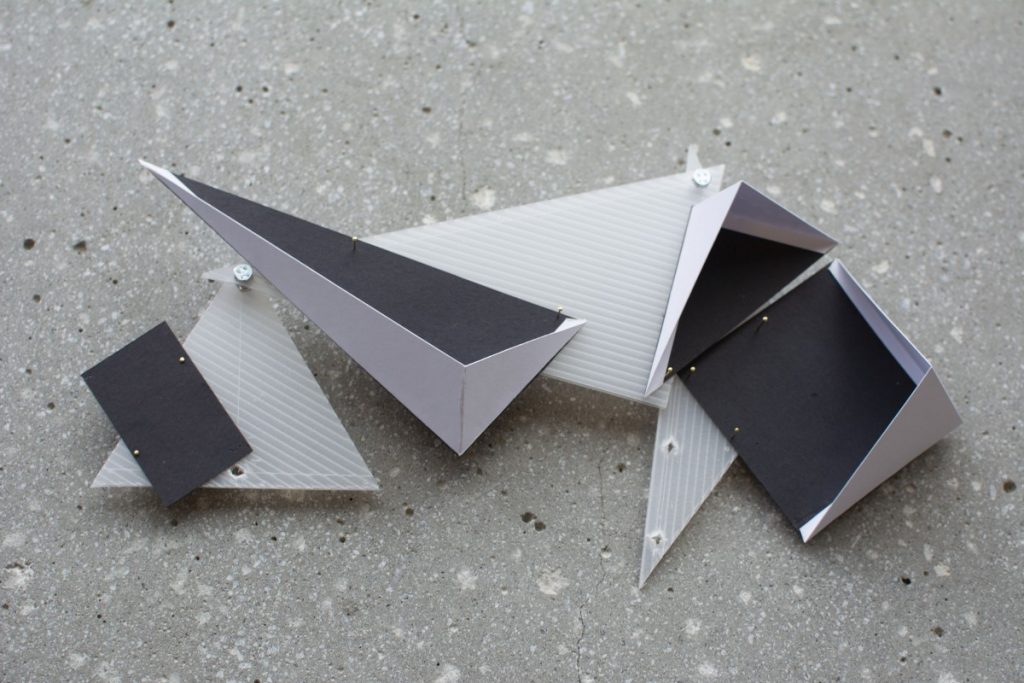
The second test was a study in multiple dimensions and axis. Attempting to assign material qualities was a challenge and therefore this direction seemed like a viable path to further explore.
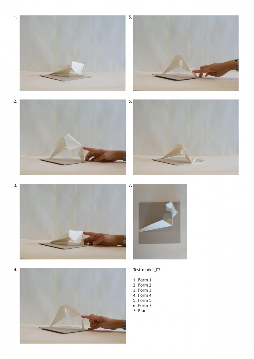
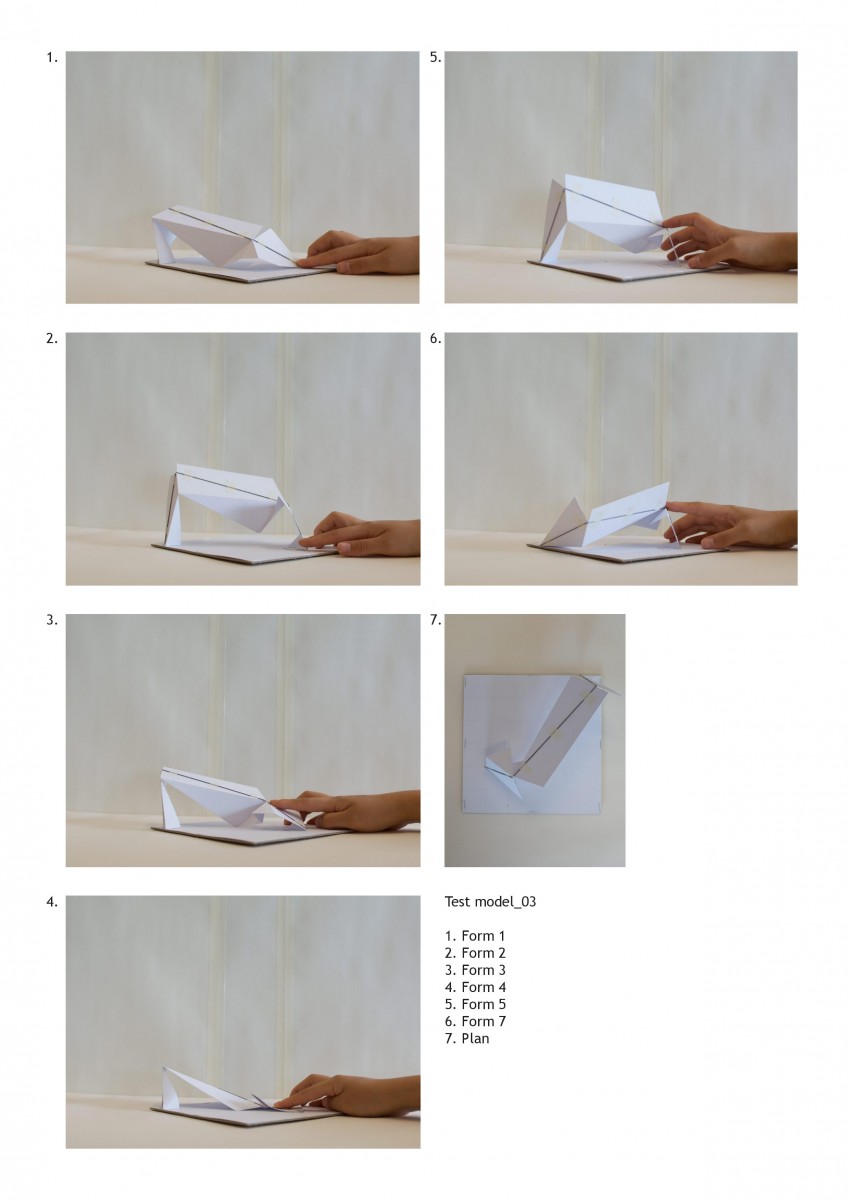
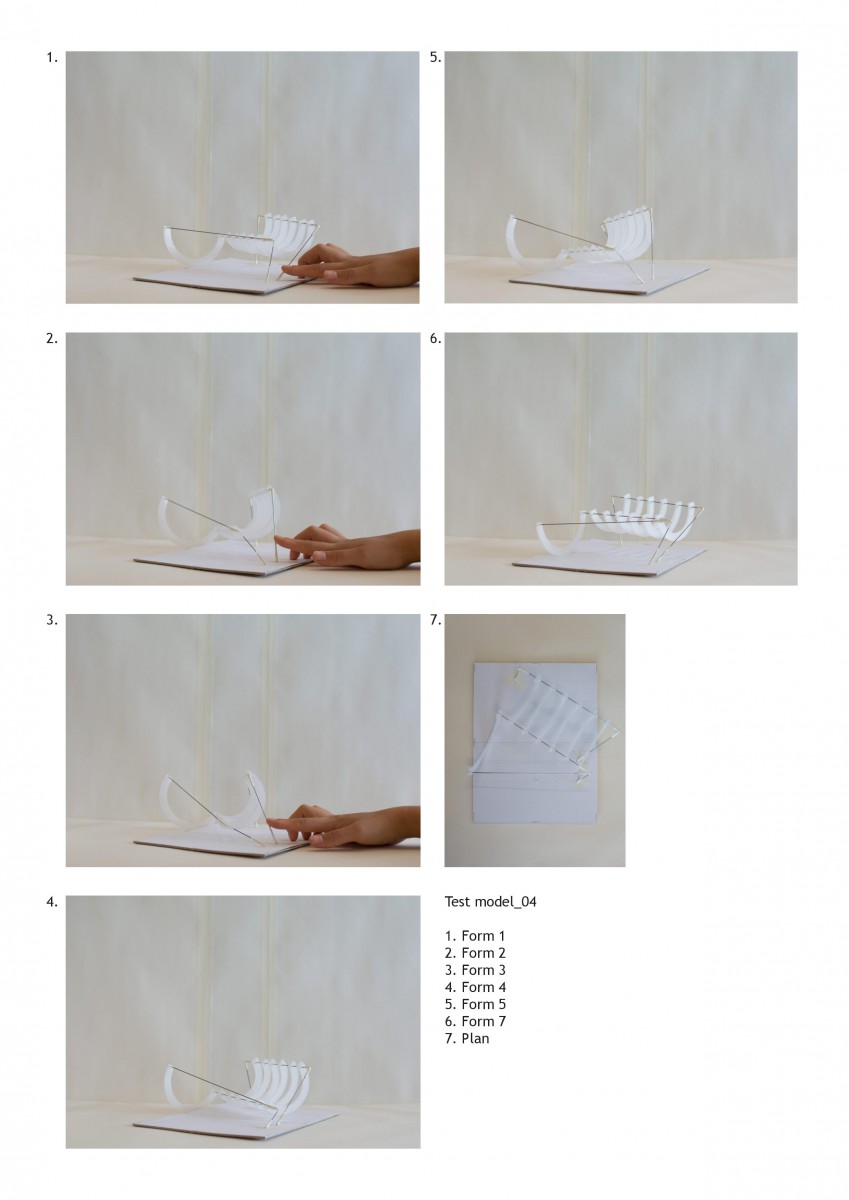
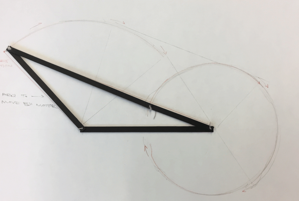
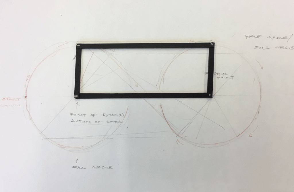
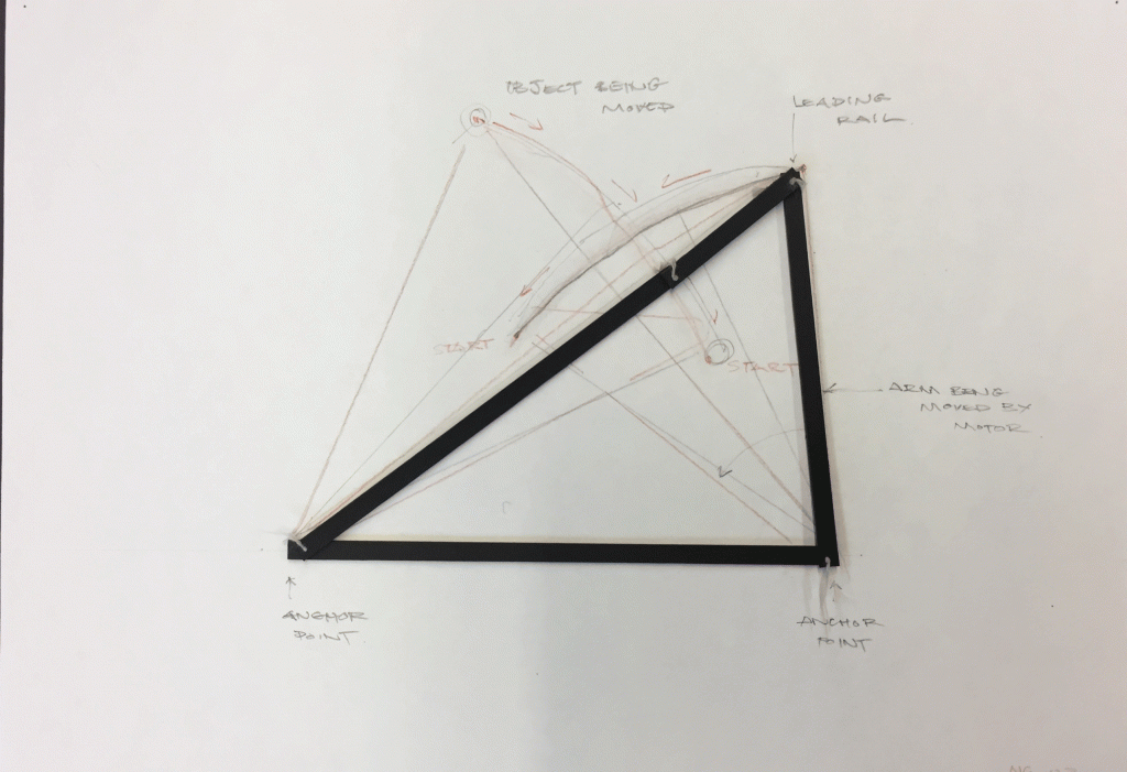
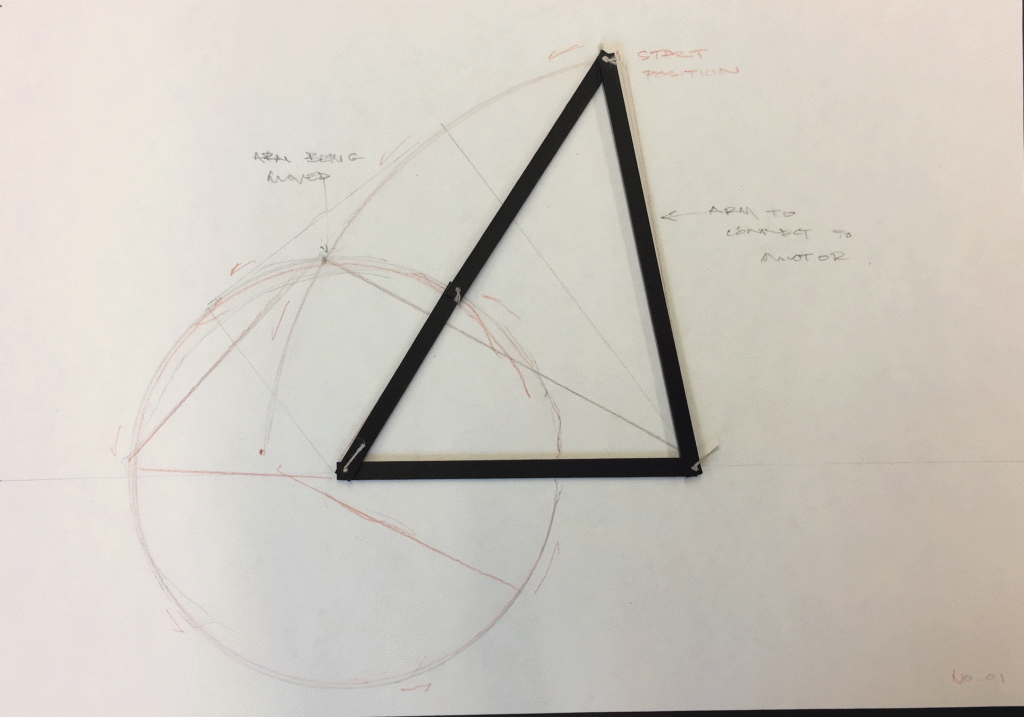
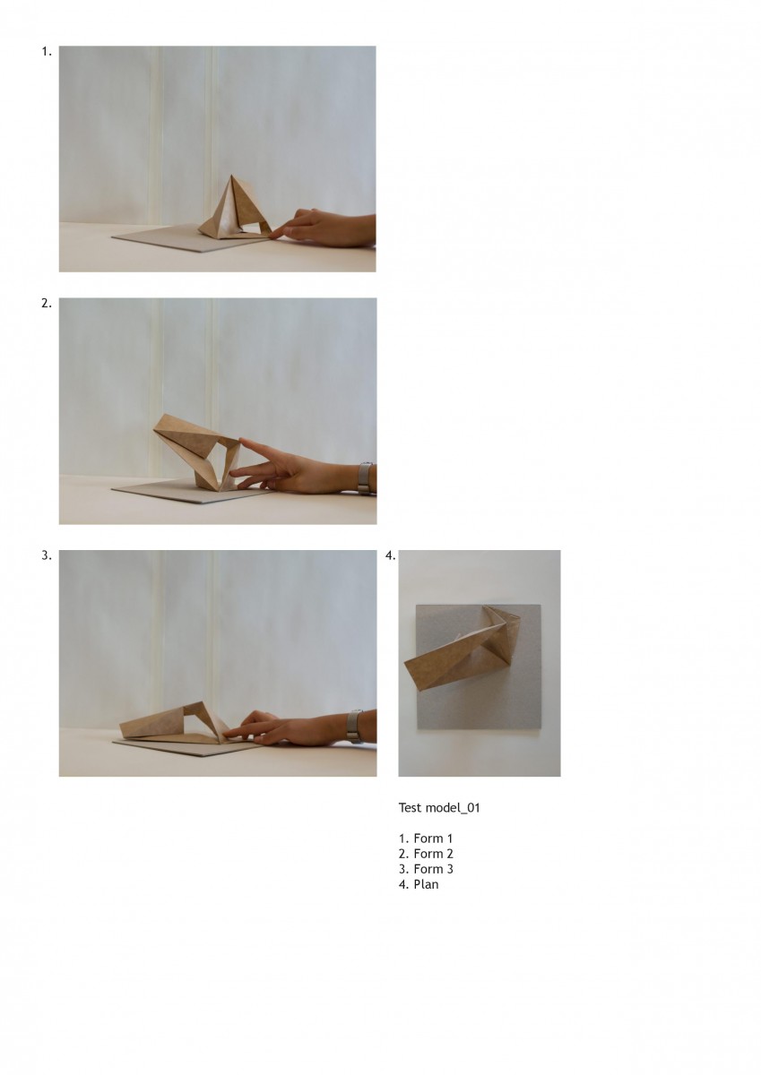
I decided to move the project forward by testing the idea of the four bar linkage across varying planes through simple paper models.

Each of these tests brought about questions of stability, connection points, anchor points, material qualities, thickness, how it meets the ground etc. Potential for the use of colour, thickness and additional elements that extend out from the four bars themselves can be observed. Although a prototype could be developed exploring a solution for such possibilities, I have not been able to push this study to that extent.

Project 3 and 4 has been a sort of research project into robotics, motorised movement and the exploration of what this other world of mobility can offer architecture. No end result as such was assigned throughout the process and I feel that that has allowed me to really understand the possibilities of these tools. I have hit many walls and found myself immersed in frustrations over what architectural meaning this project presents but overall, it has been incredibly fun and challenging taking an alternative approach to architectural design.

P4.T1.Linkages

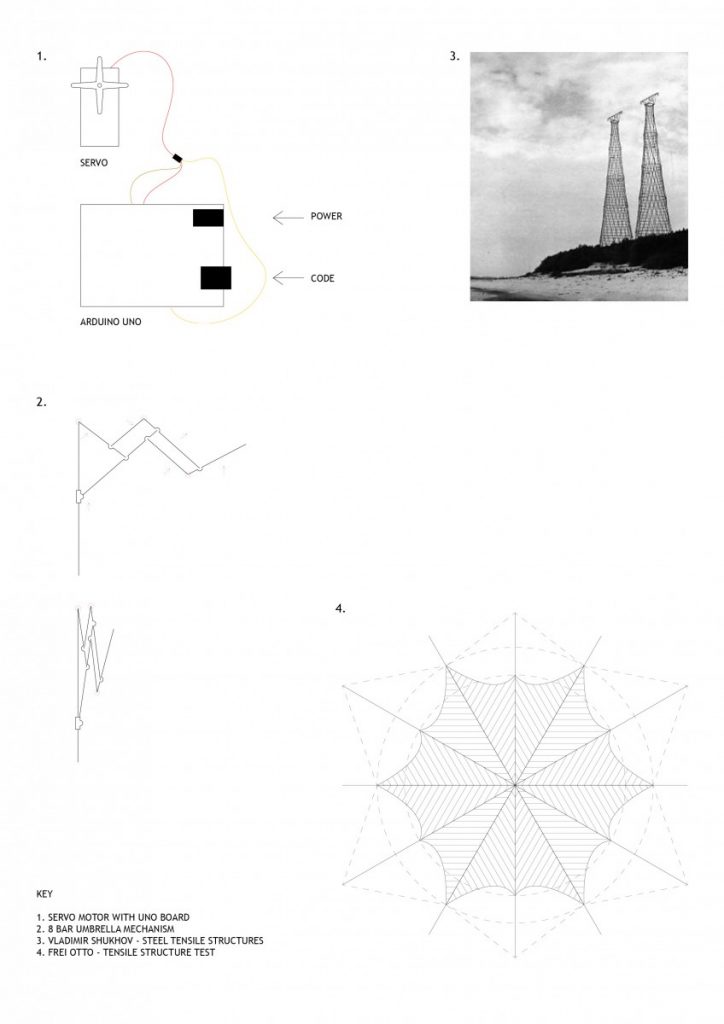
Project 04 saw a move to material prototyping and developing a methodology for building three dimensional forms. I looked into Frei Ottos fabric tensile structures as well as engineer Vladimir Shukhovs steel tensile structures as precedent.

Keeping the automated robotic theme running I also decided to incorporate a servo motor into my design process. This brought a moving element to the prototyping and prompted the research into the umbrella mechanism and three/ four point linkages.

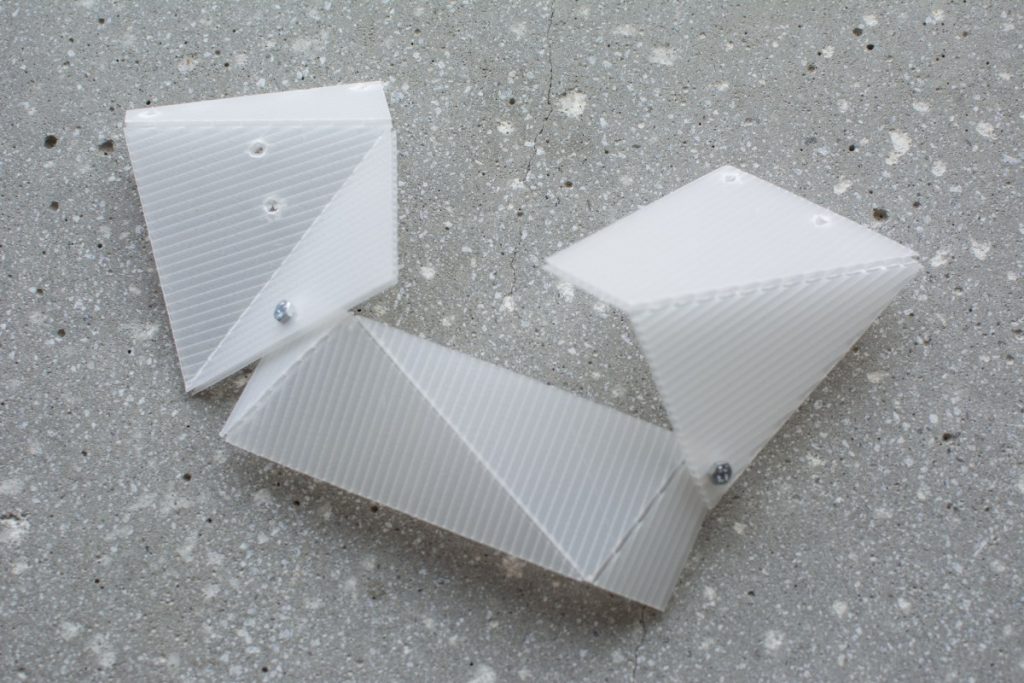
I also explored the Kaleidocycle (flexagon) which are models of linked tetrahedra which turn through their centres. I wanted to incorporate these methods for materials that, through their connection, could change form and produce multiple spatial environments.

iv. movement simulation and data management

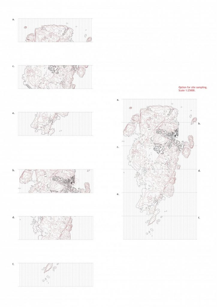
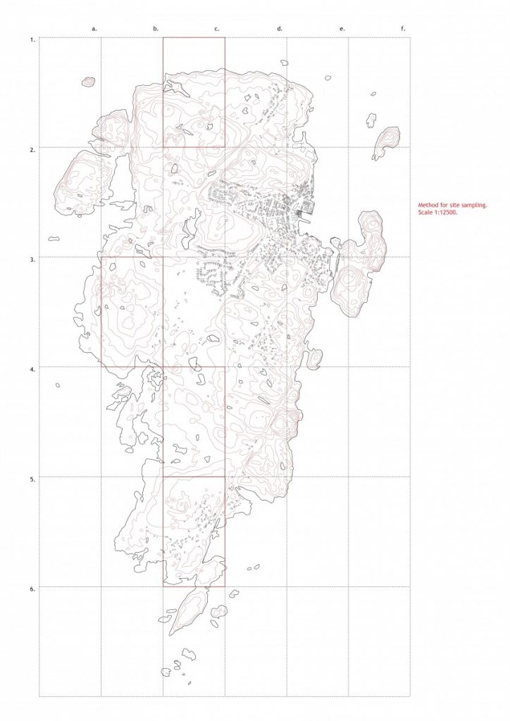
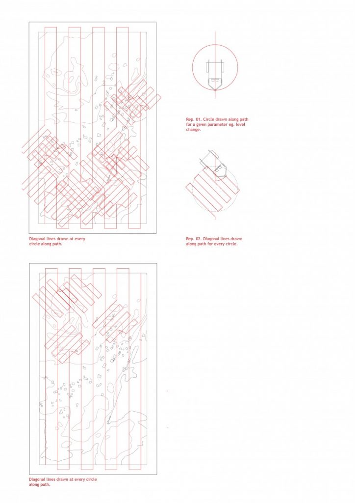
Moving on from the last pin-up I needed a better management strategy for the site data. When the robot reads and responds to the site it needs to be at a scale that the data is useable and realistic for the architectural design to be implemented. Providing a grid system allowed a reading of the entire terrain in greater detail where each grid tile can be blown up and analysed. Consideration was also taken for the dimensions of a manageable testing area for repeated demonstrations and data collection. Below are two possible methods of grid reading of the site. The maps were sampled at 1:500 scale with the second method of grid division.

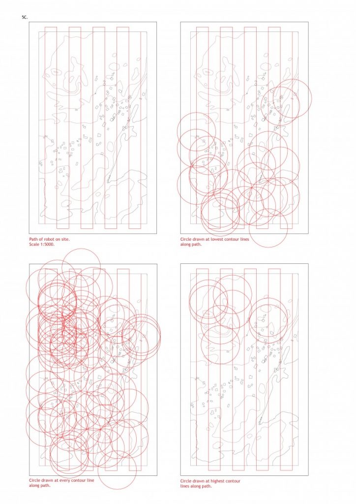
The robot has a narrow range of testing limited to its line and ultrasonic sensors. This provides a linear path of testing at 1cm intervals on the sample map which would be every 50metres in real life. This gives a dimension and scale to any output that will be collected. In the simulation drawings, the robot is to respond to the changes in height at any level changes, changes at the highest and lowest areas. The output is a full 360 rotation of the robot leaving circles as the response. The robot is allowed to respond to its generated data again and draw diagonal lines at a 45 degree angle at every circle. This then gives a criss cross of linear data that the building system of precast members could be assembled upon.