Project 4: Material Transactions

Architecture is how the person places herself in a space. 
Fashion is about how you place the object on the body.

Zaha Hadid

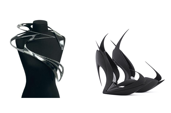
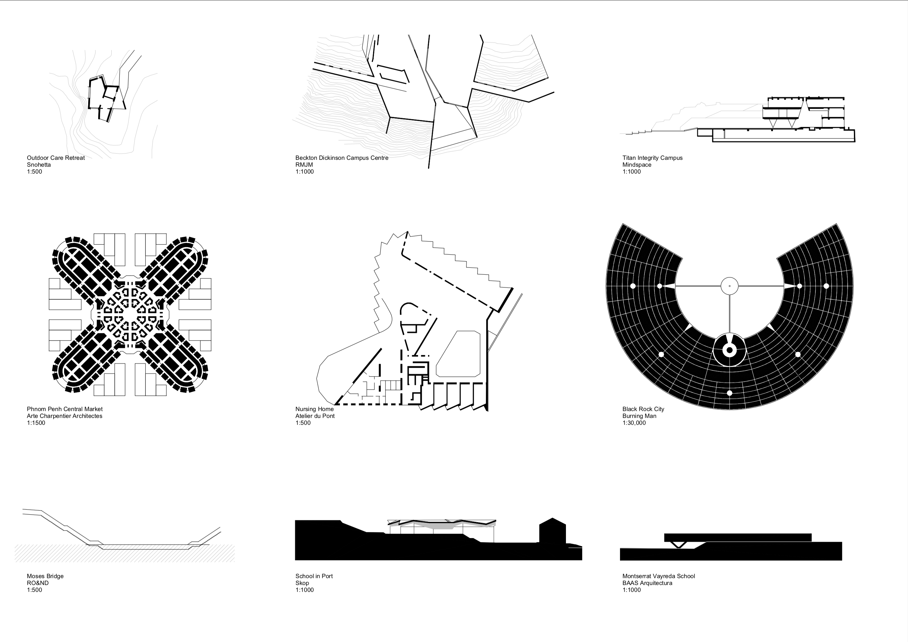
Many references are available for fashion that is inspired by the forms and techniques of architecture. 

This project is an exploration of the reverse- architecture that is inspired by the forms and techniques of fashion. 

Pattern drafting on a mannequin

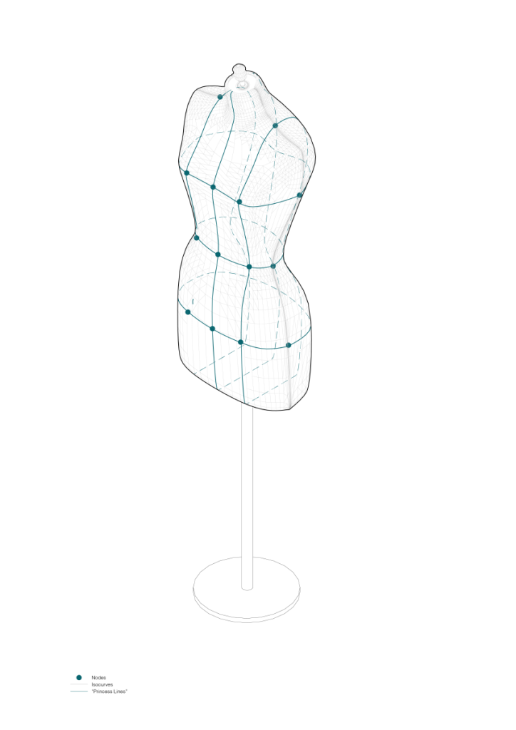
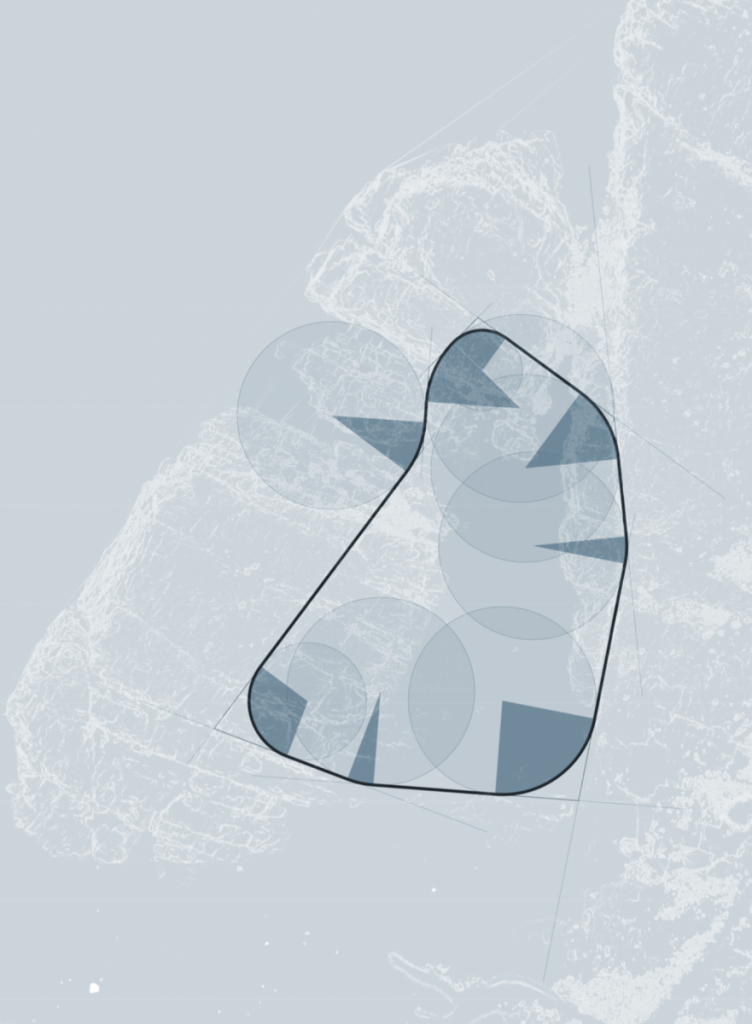
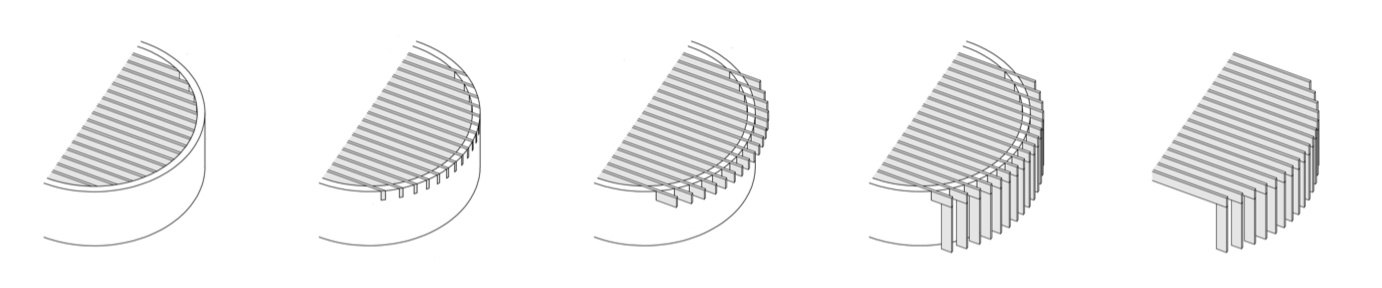
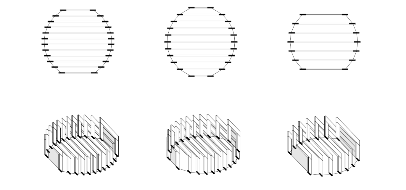
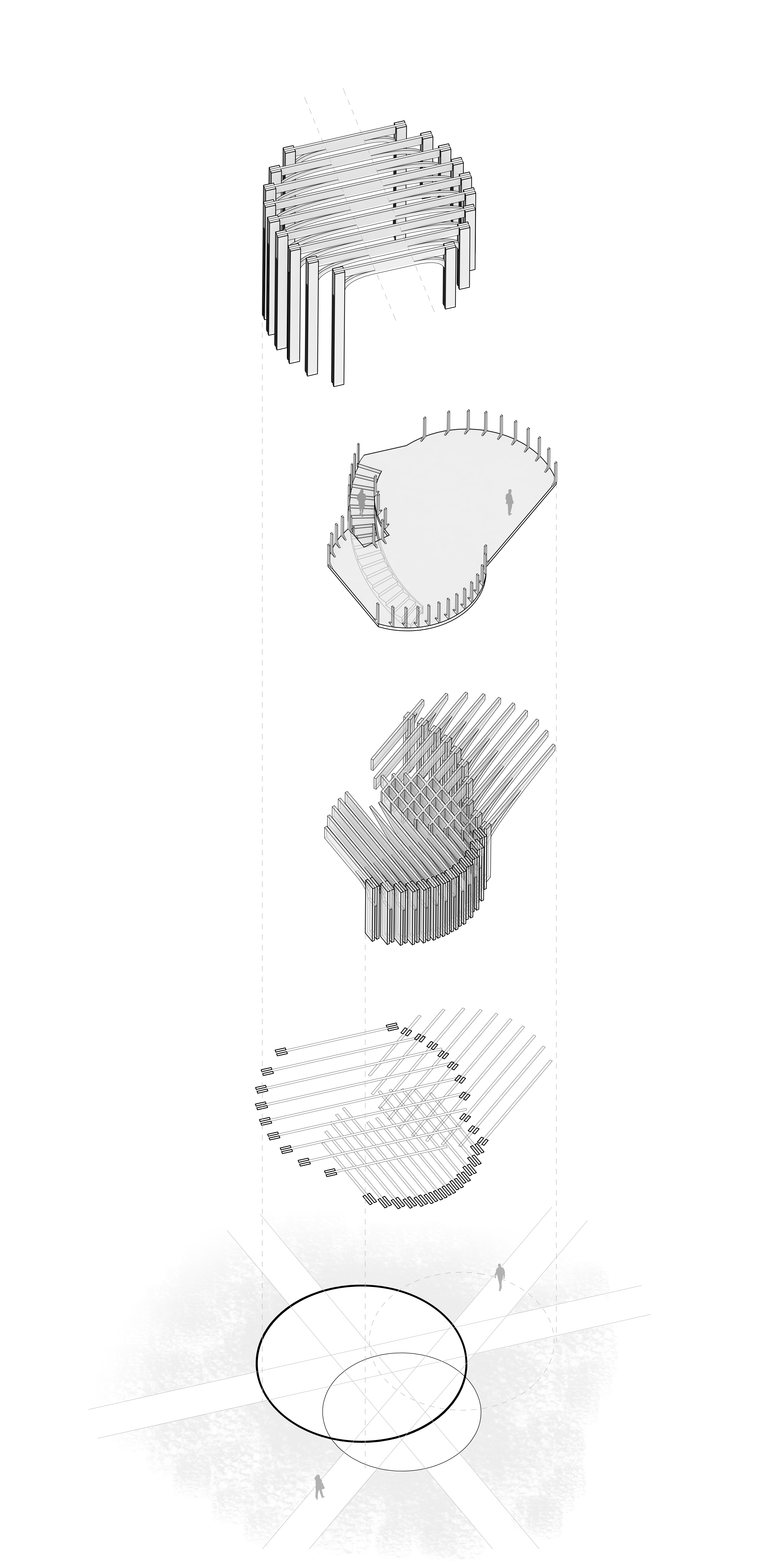
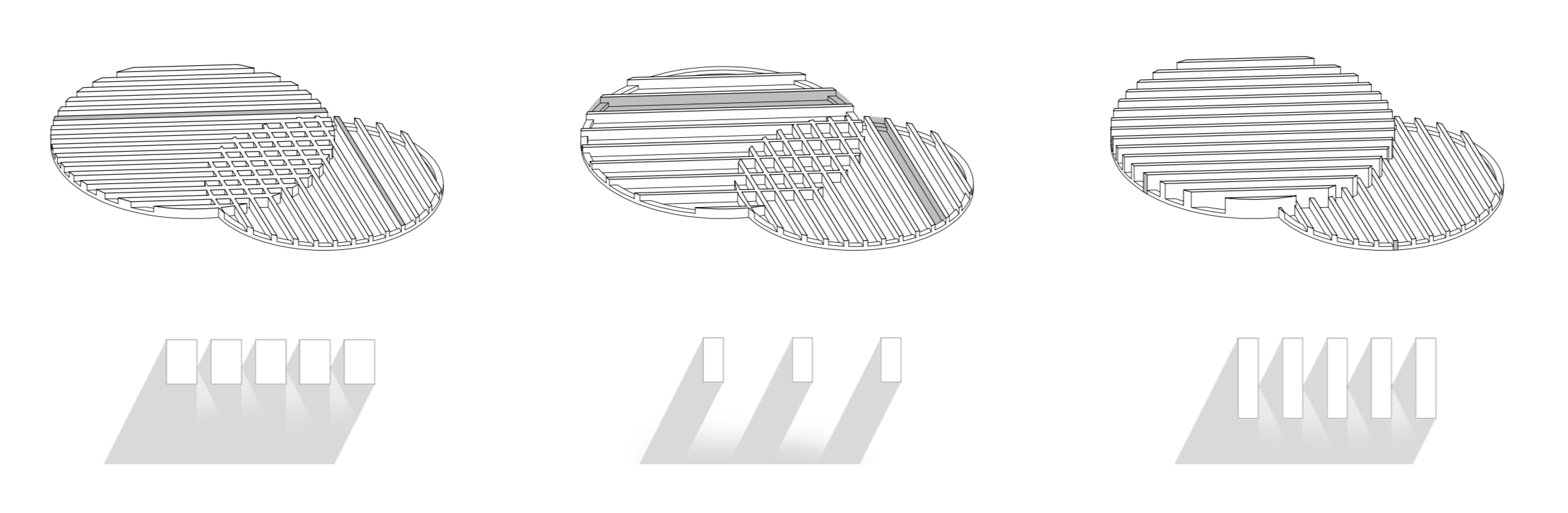
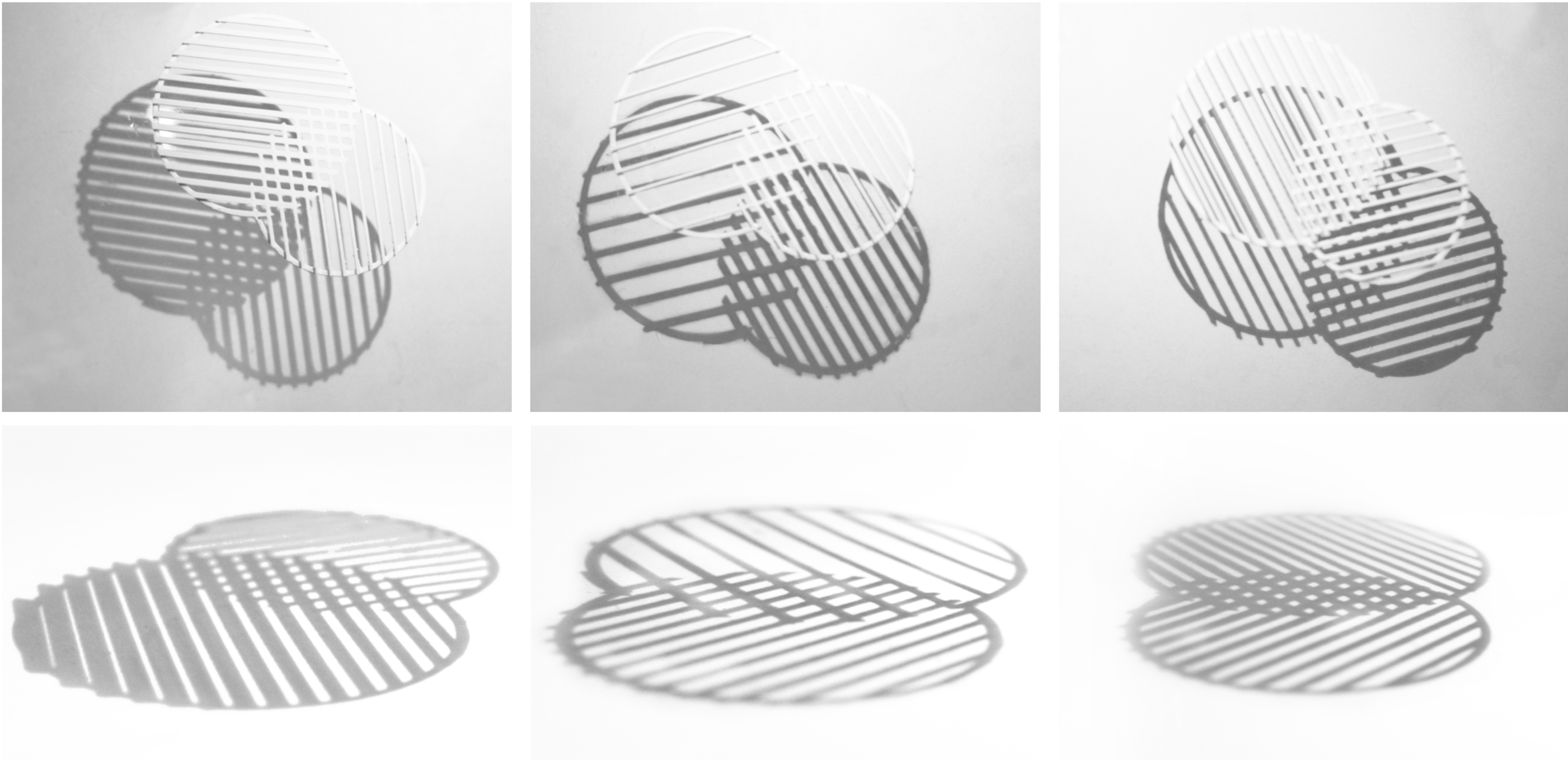
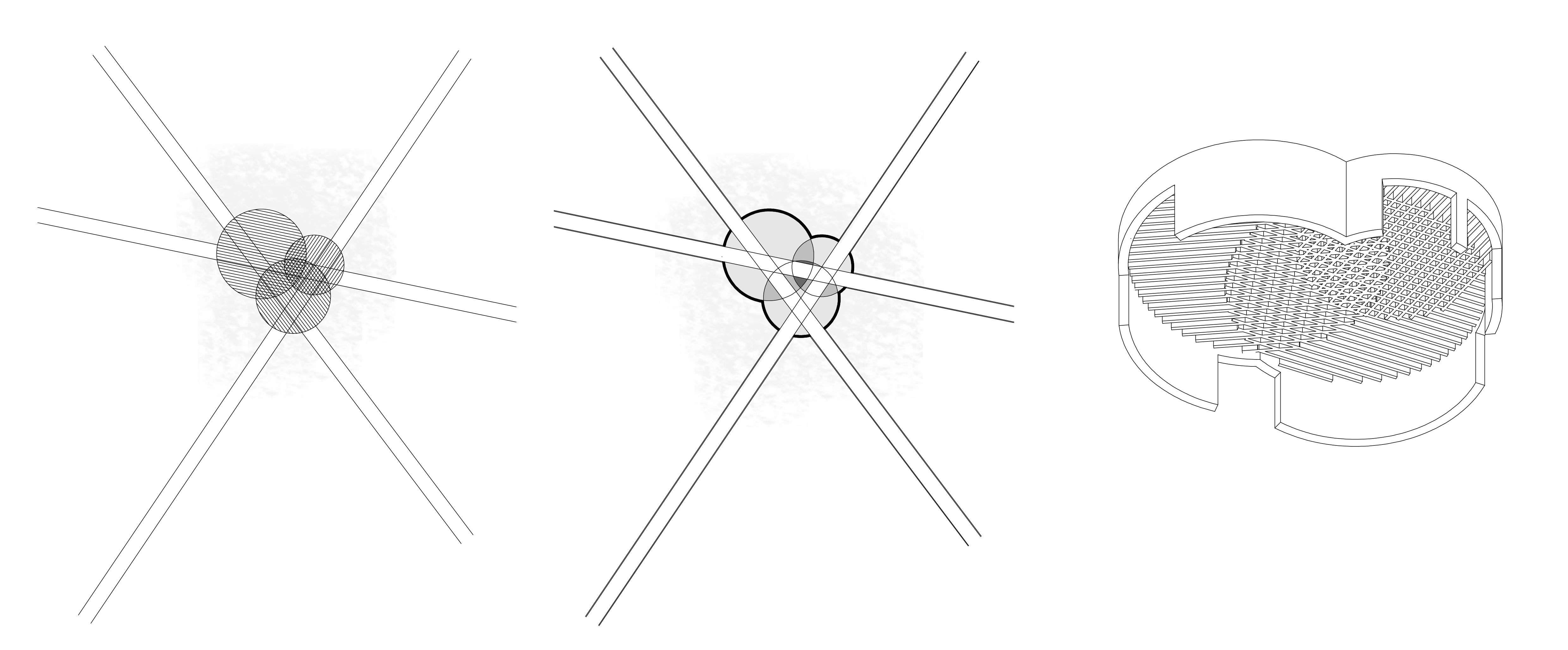
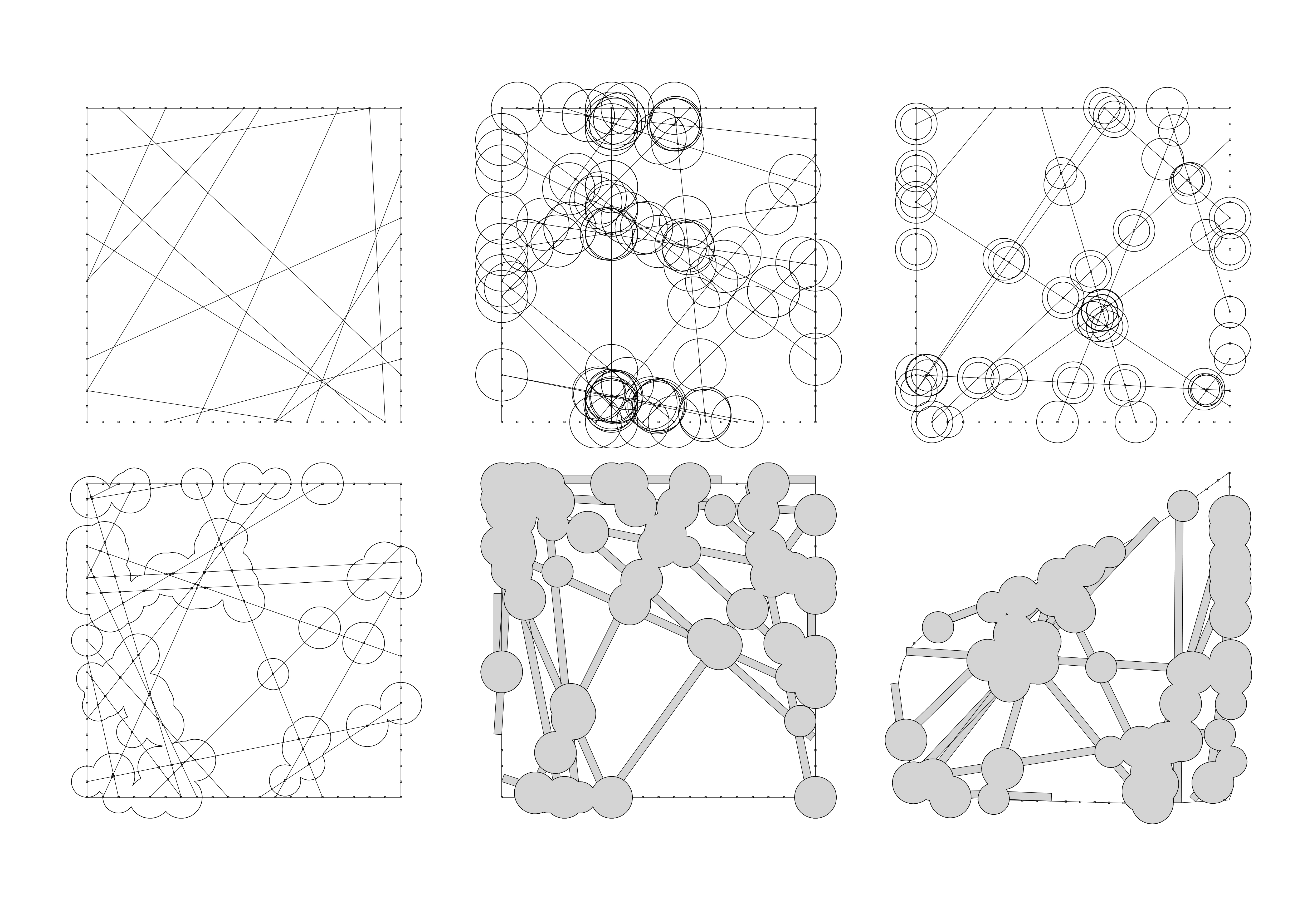
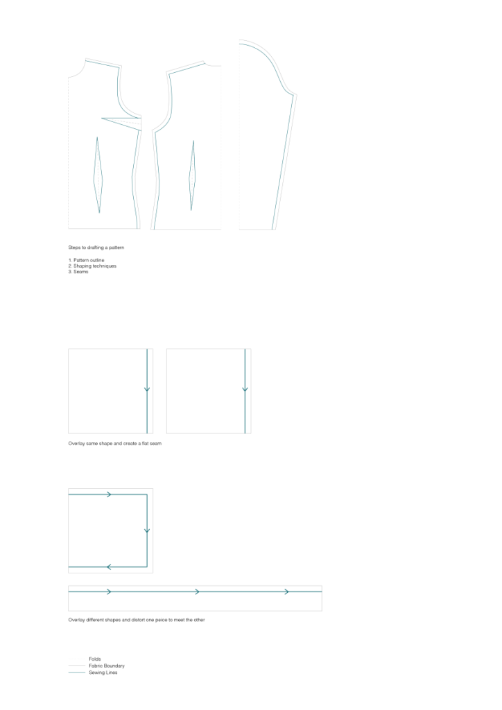
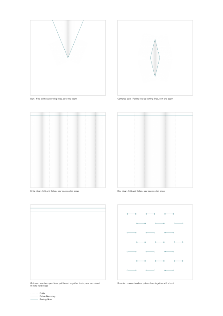
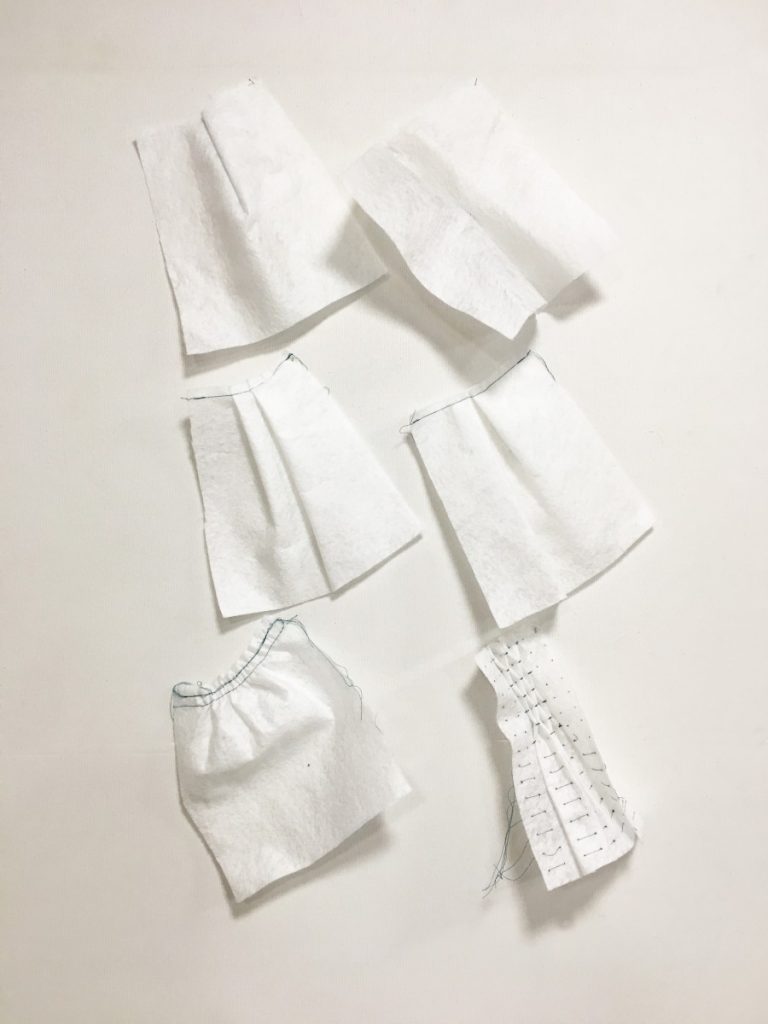
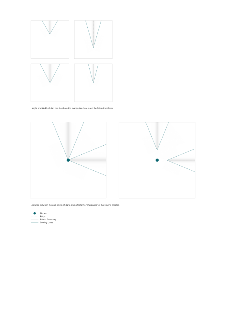
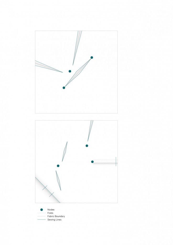
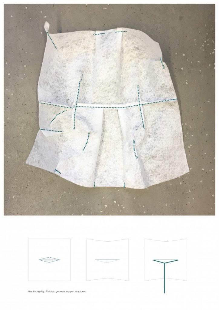
Traditional pattern drafting techniques involve finding ‘nodes’ along a figure that have the maximum amount of curvature. Fabric is then draped starting at these nodes, and adding shaping techniques to fit the fabric to the form.

Pattern drafting methods
Fabric shaping techniques
Test models of sewing techniques to observe geometry
Darts in more detail

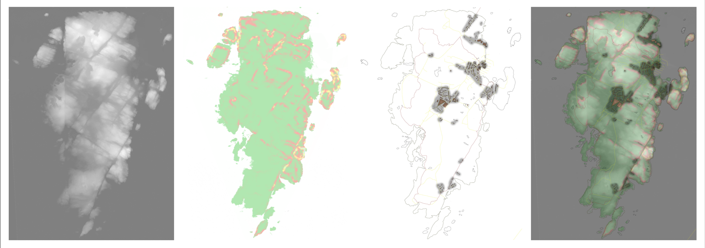
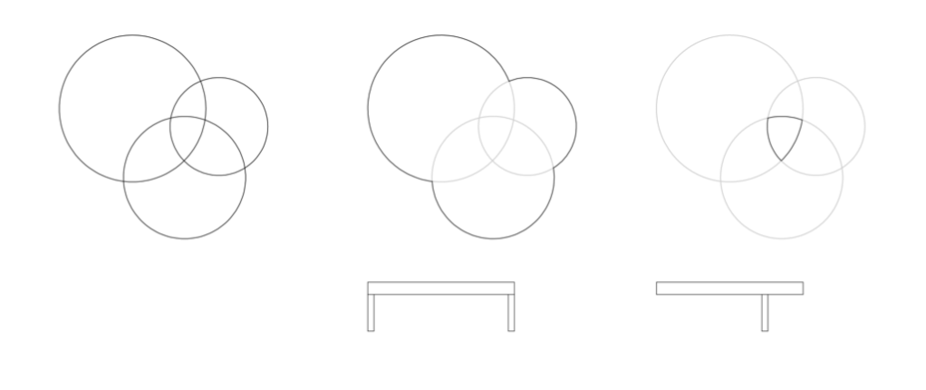
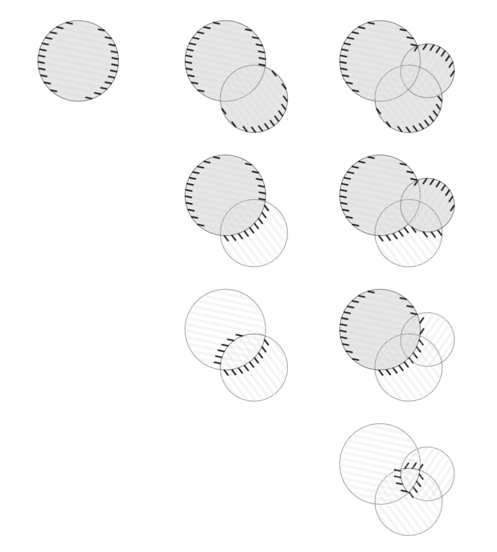
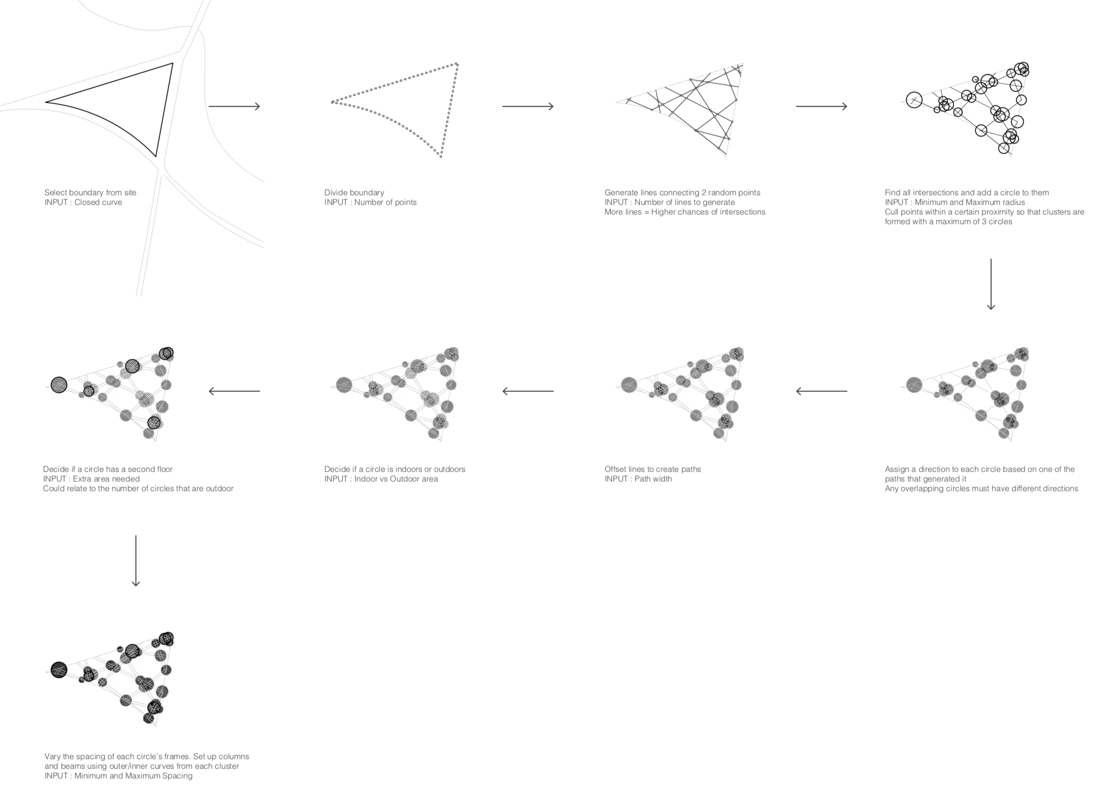
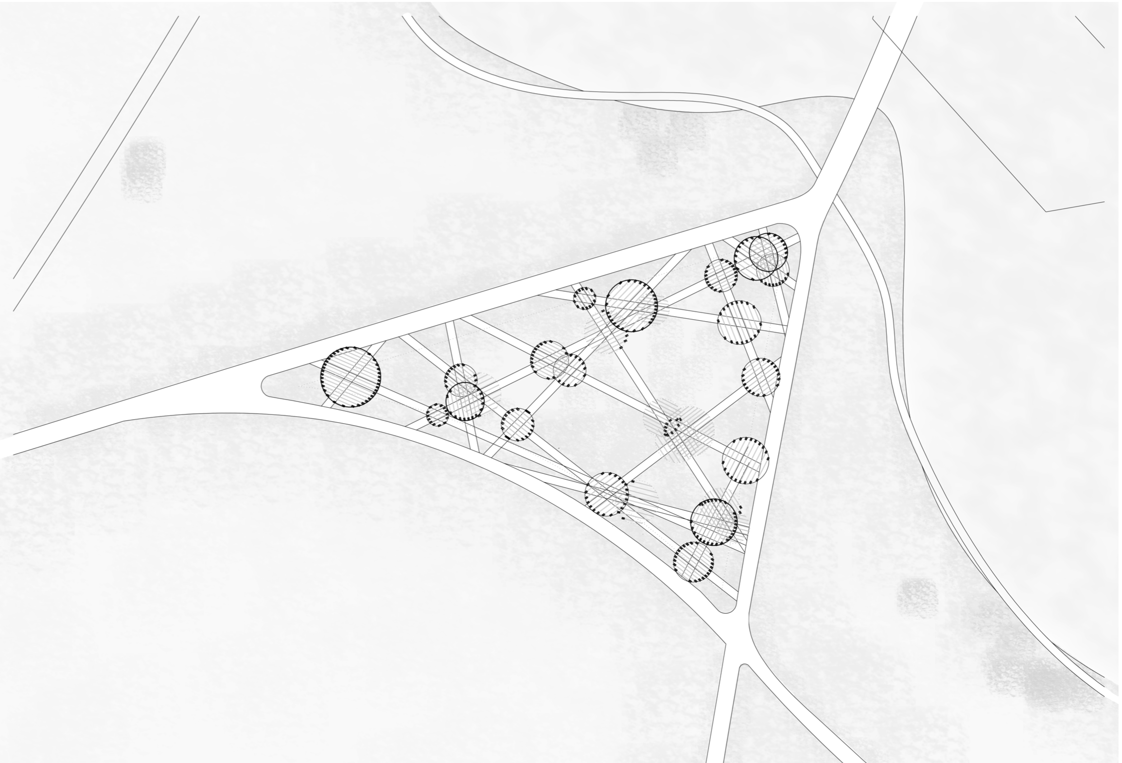
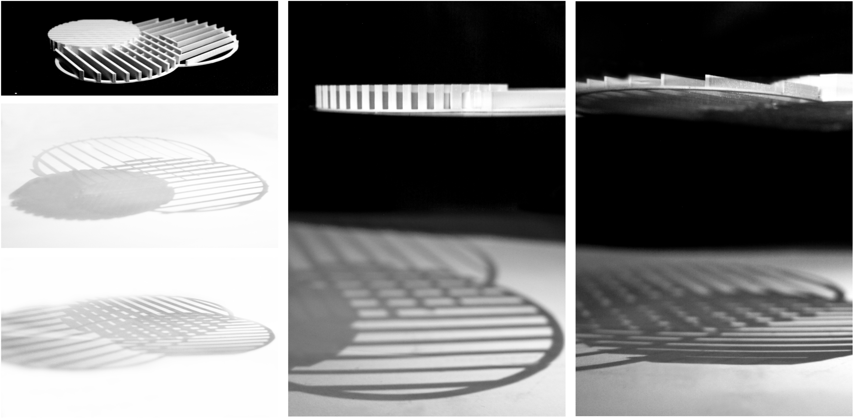
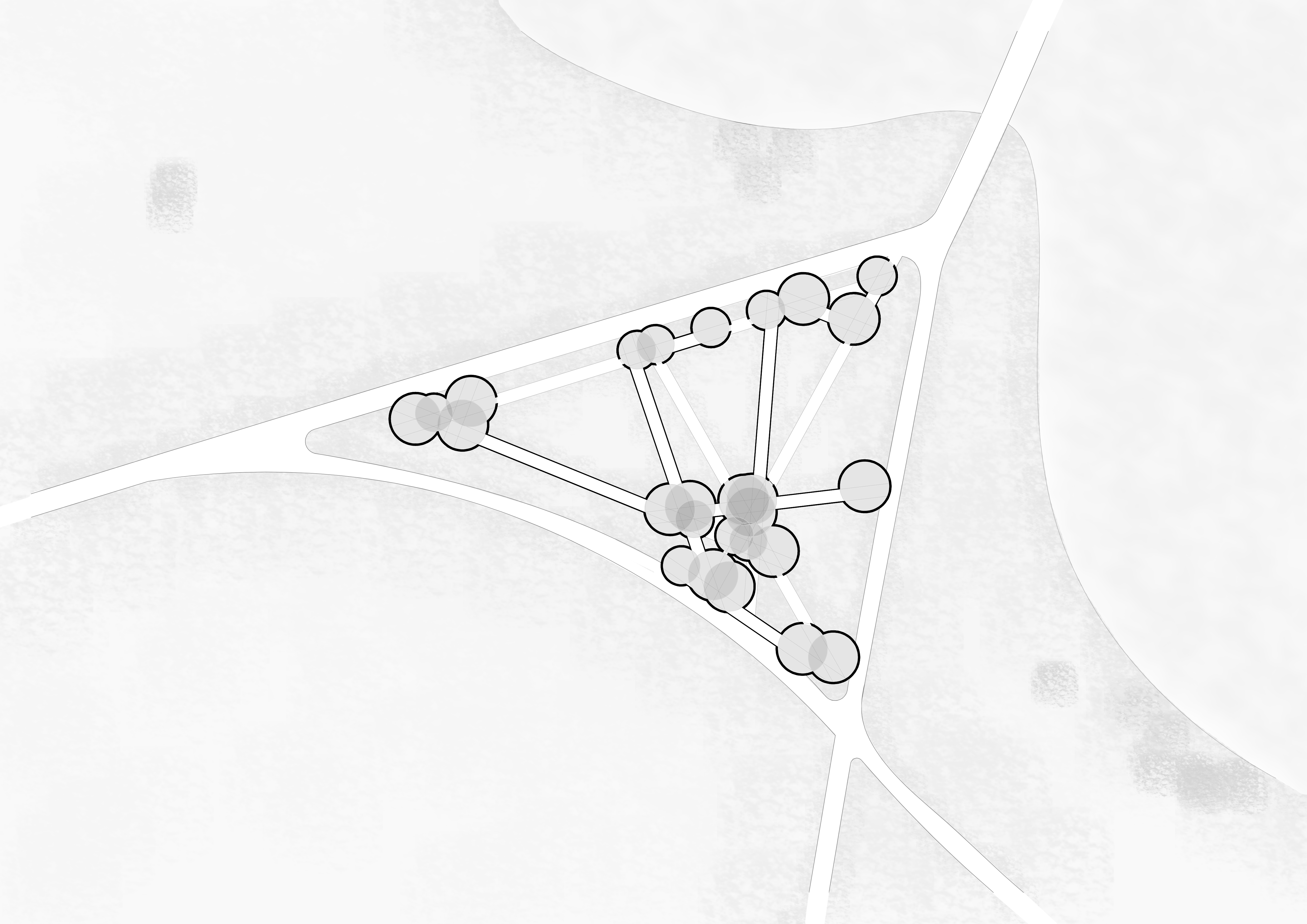
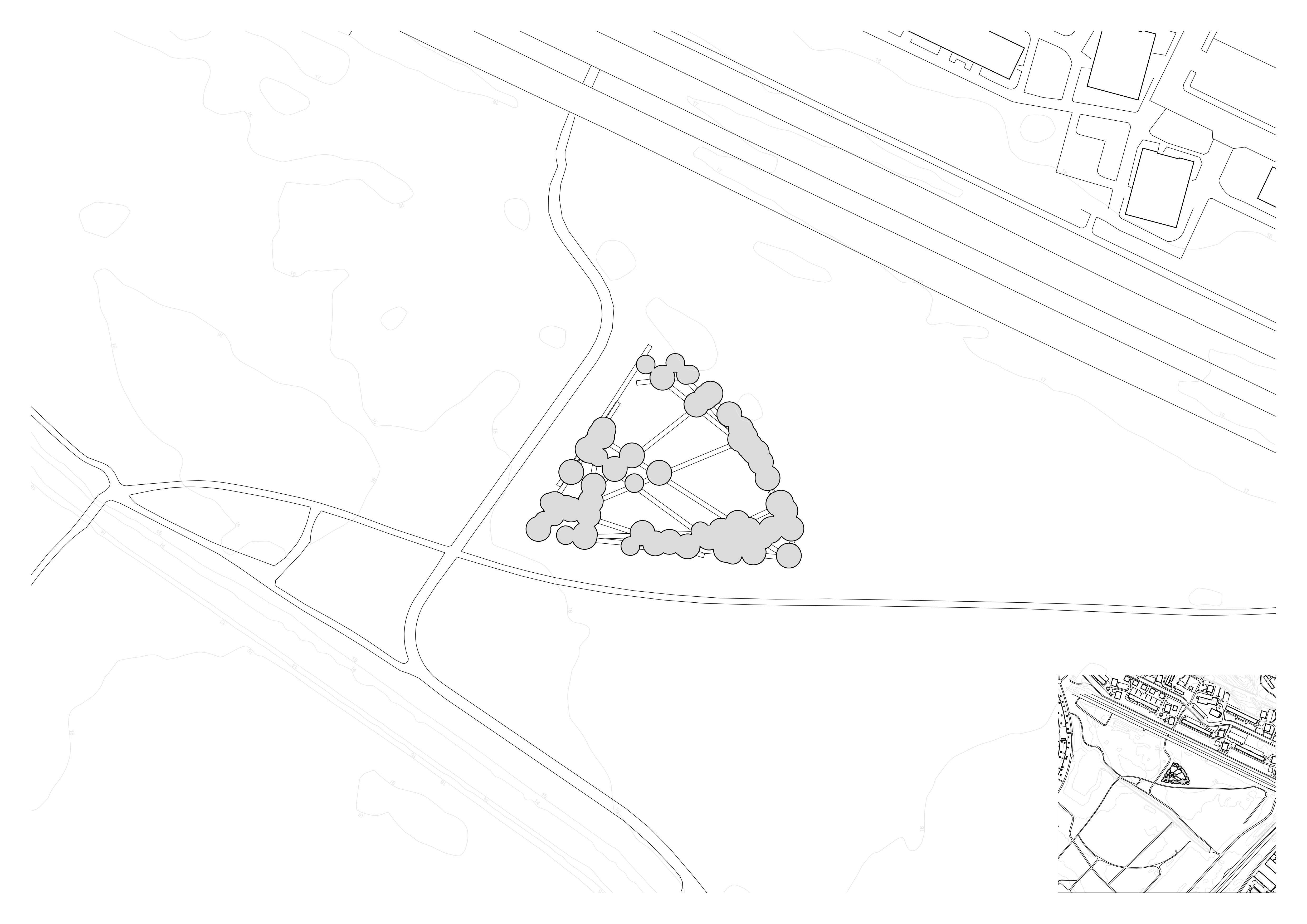
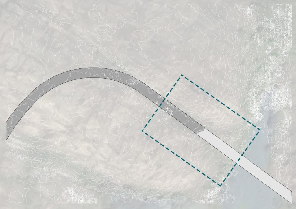
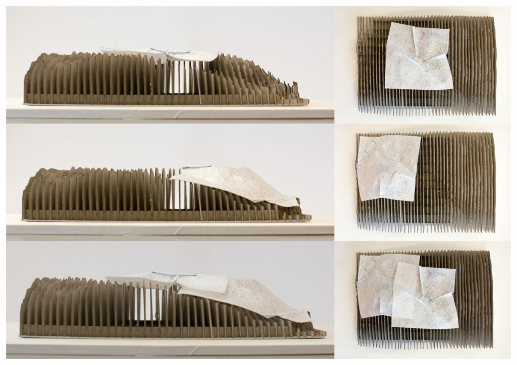
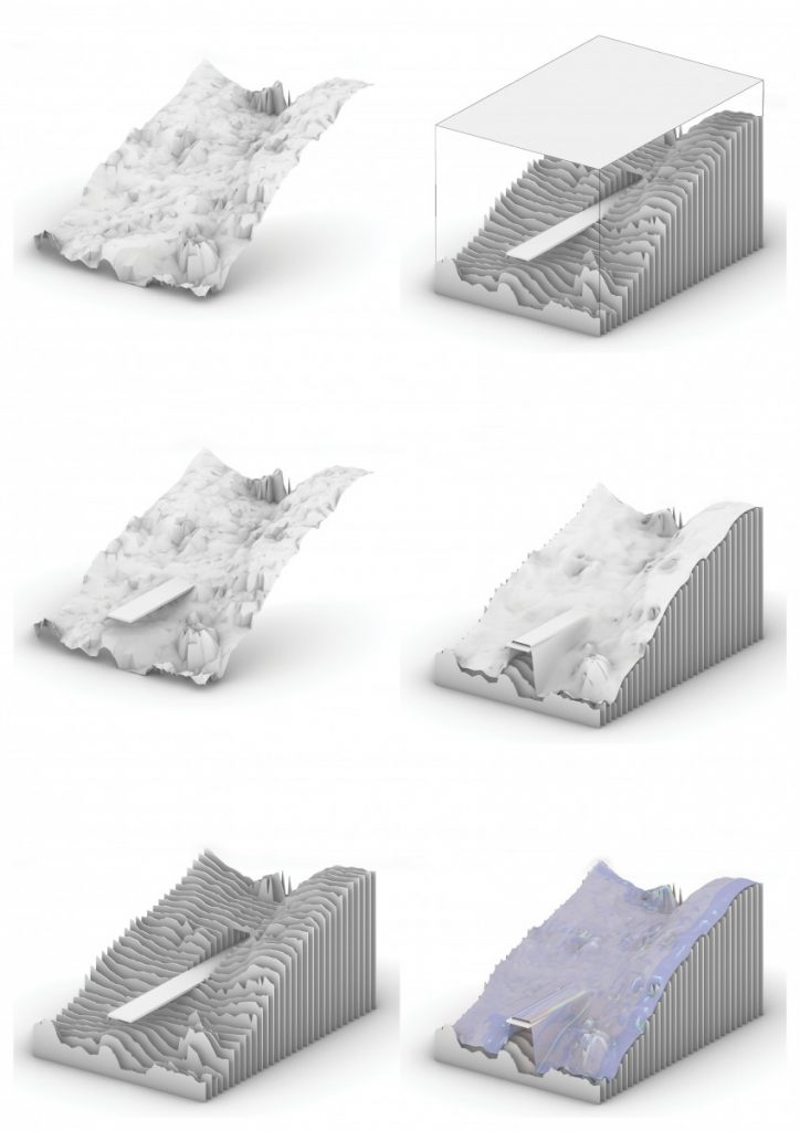
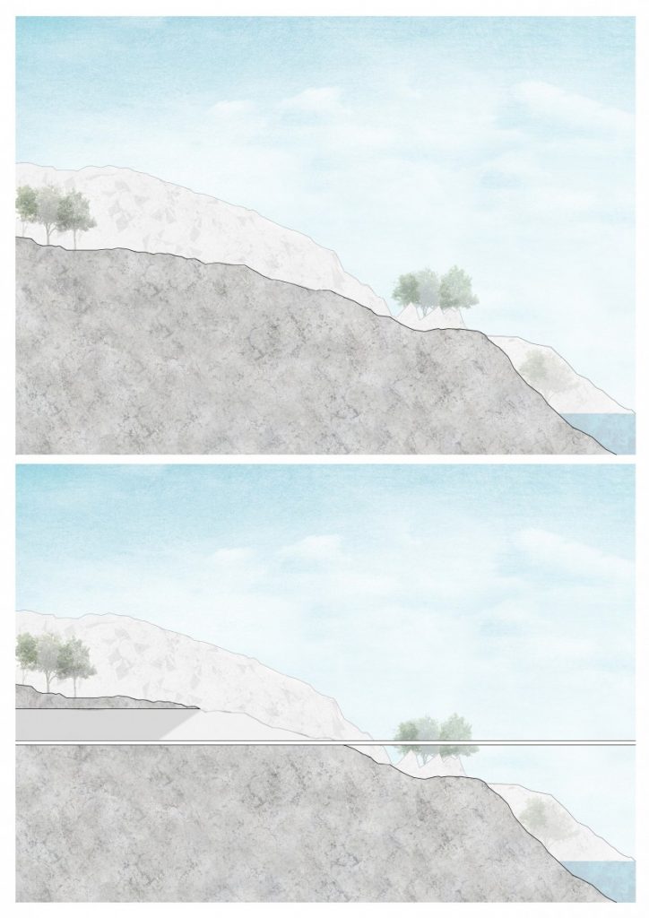
My next step is to apply this process to the site topography. The area I have chosen to work with is where the children’s sleeping quarters are, as it has a variety of scenarios related to the position of the path in the landscape.

Site plan

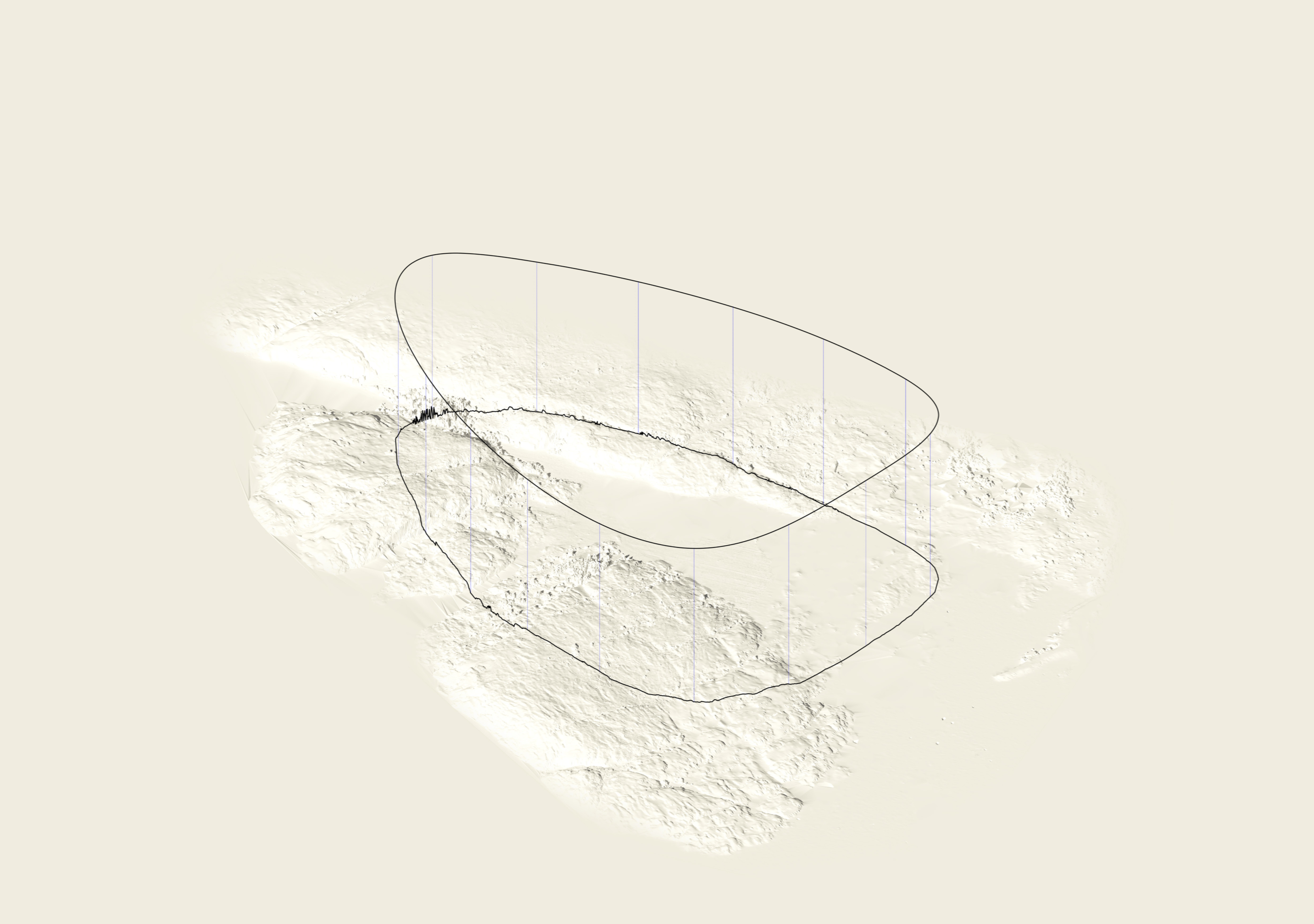
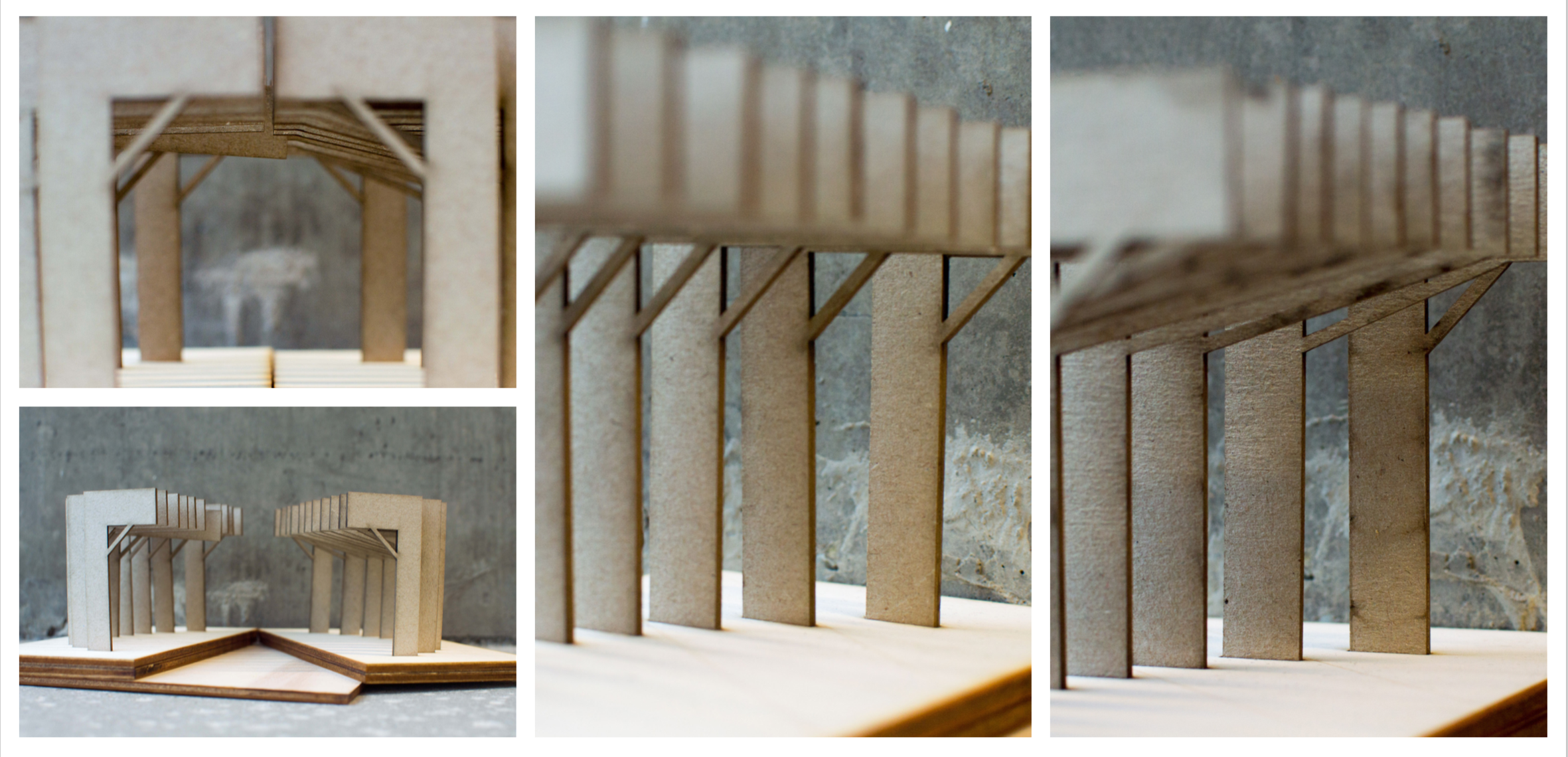
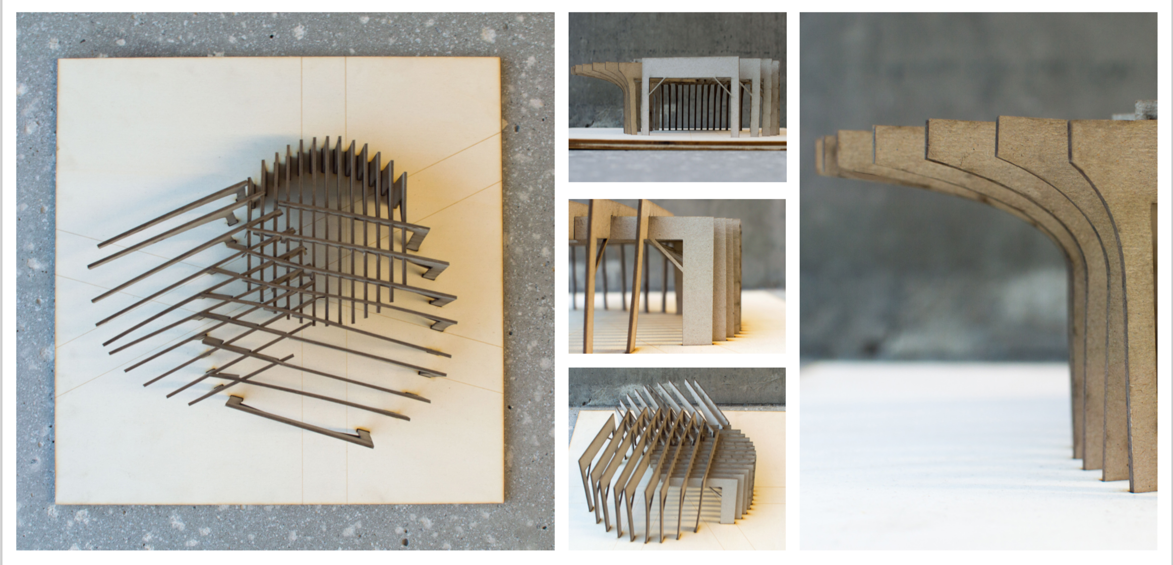
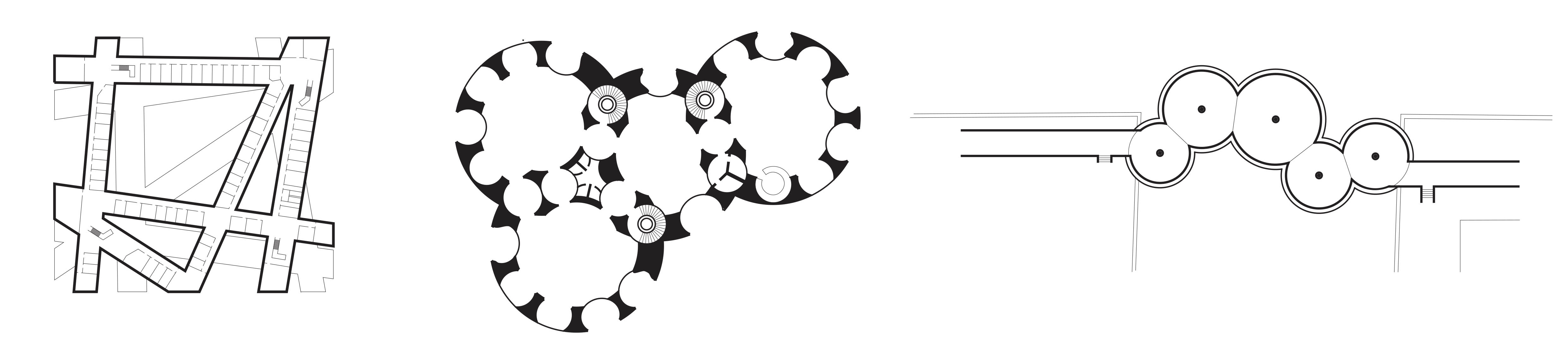
To do this, I have made a site model which I use as a sort of mannequin. The process involves laying fabric over the model, pushing it into the nodes and pinching darts and pleats into it to mould it to the site.

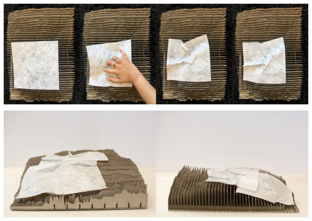
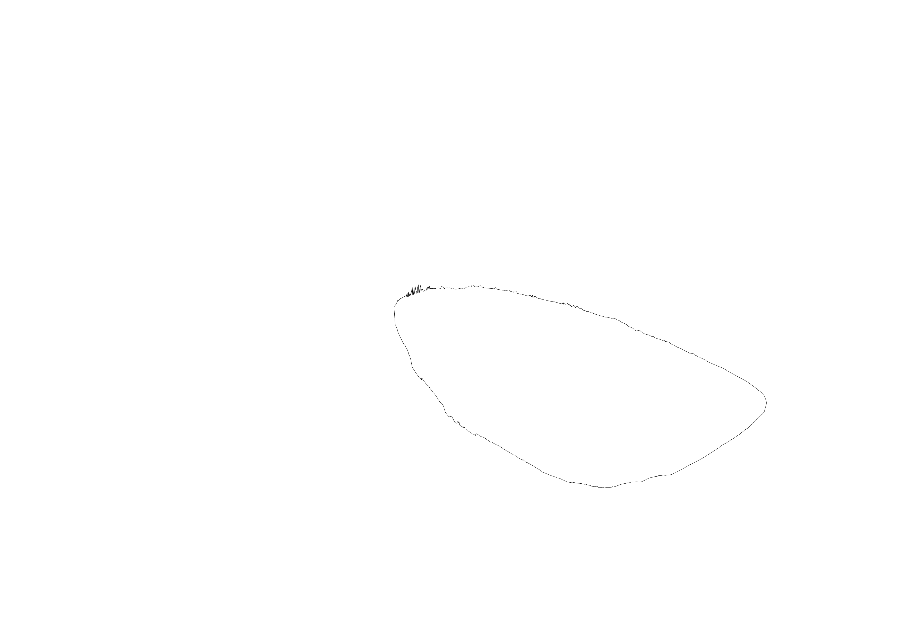
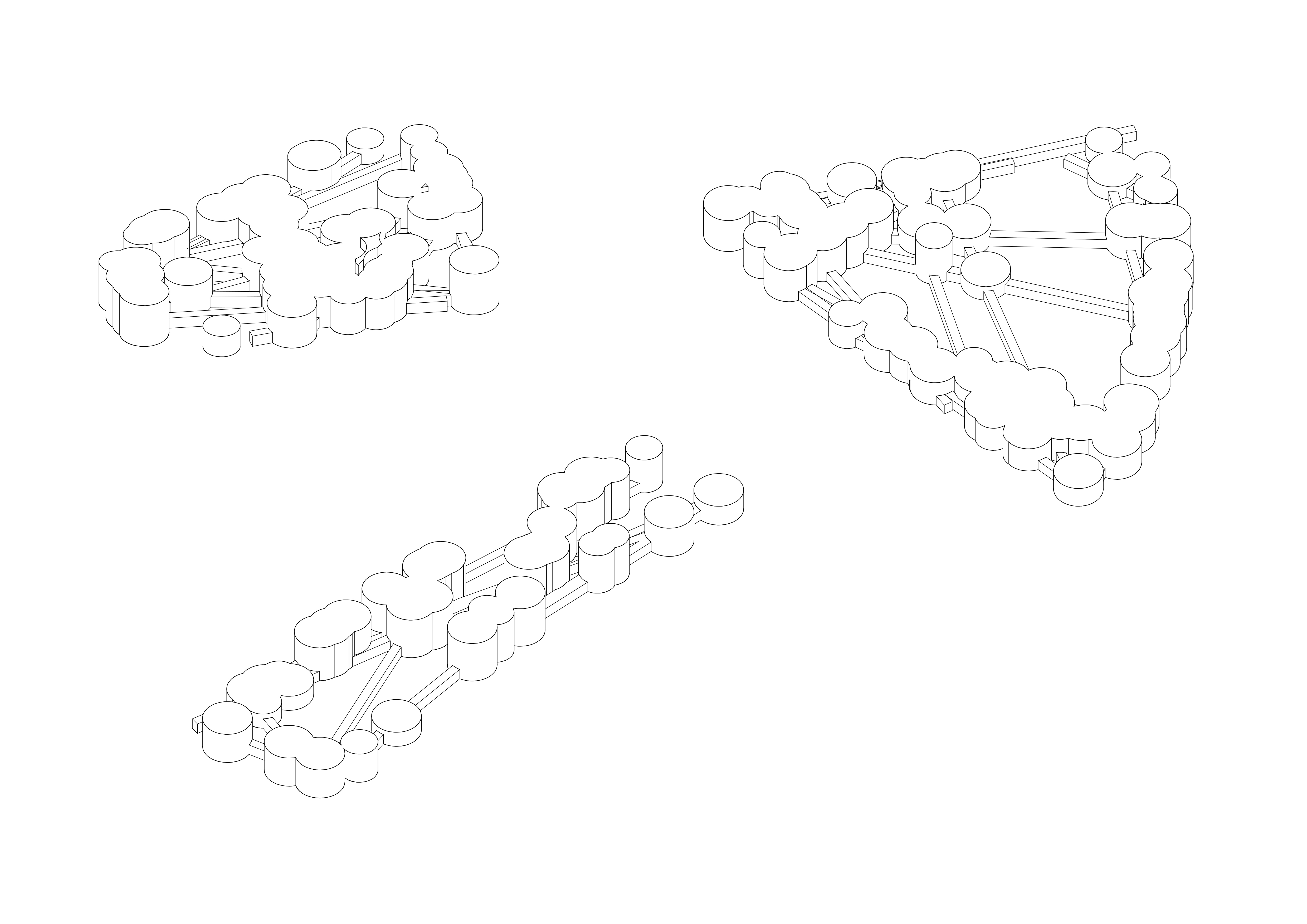
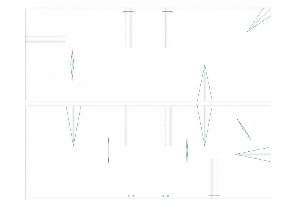
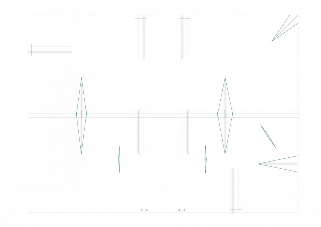
These fabric models can be unfolded into patterns, that can be repeated to create the same complex forms.

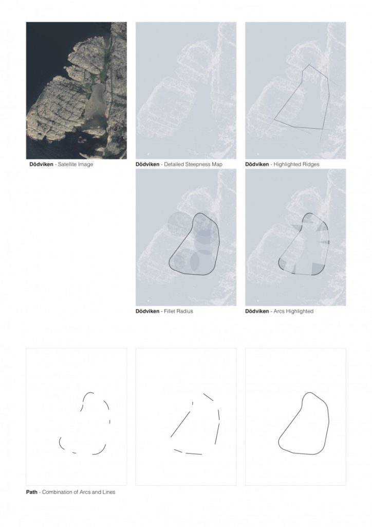
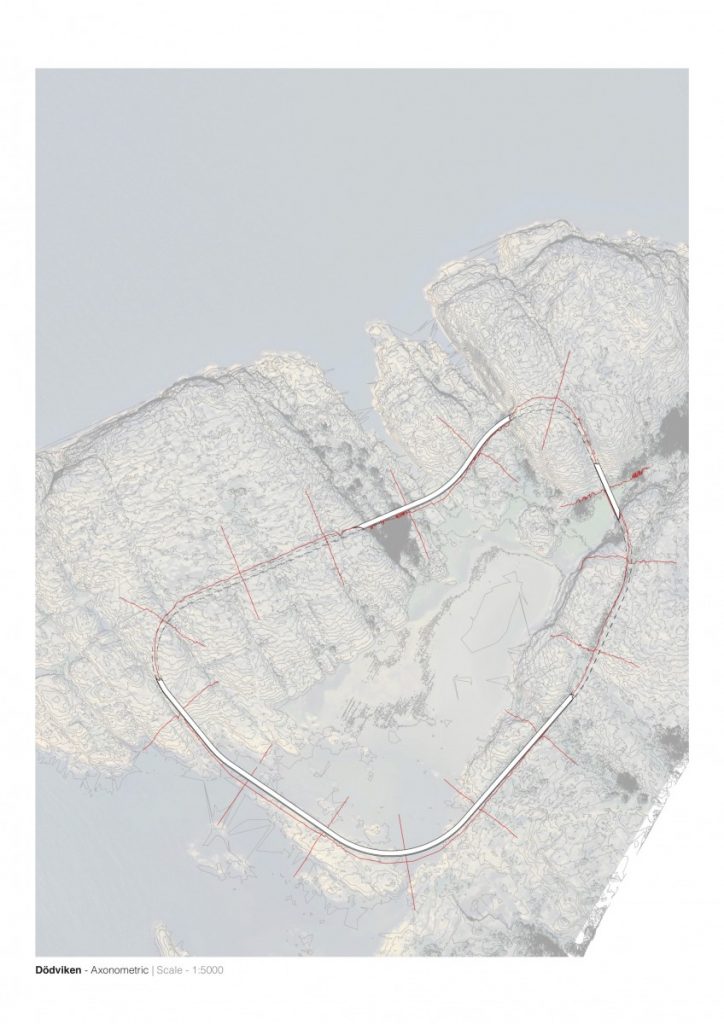
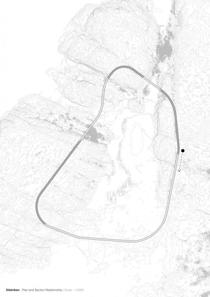
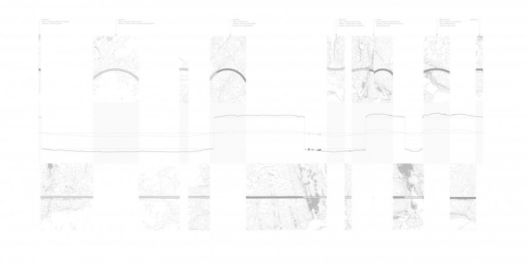
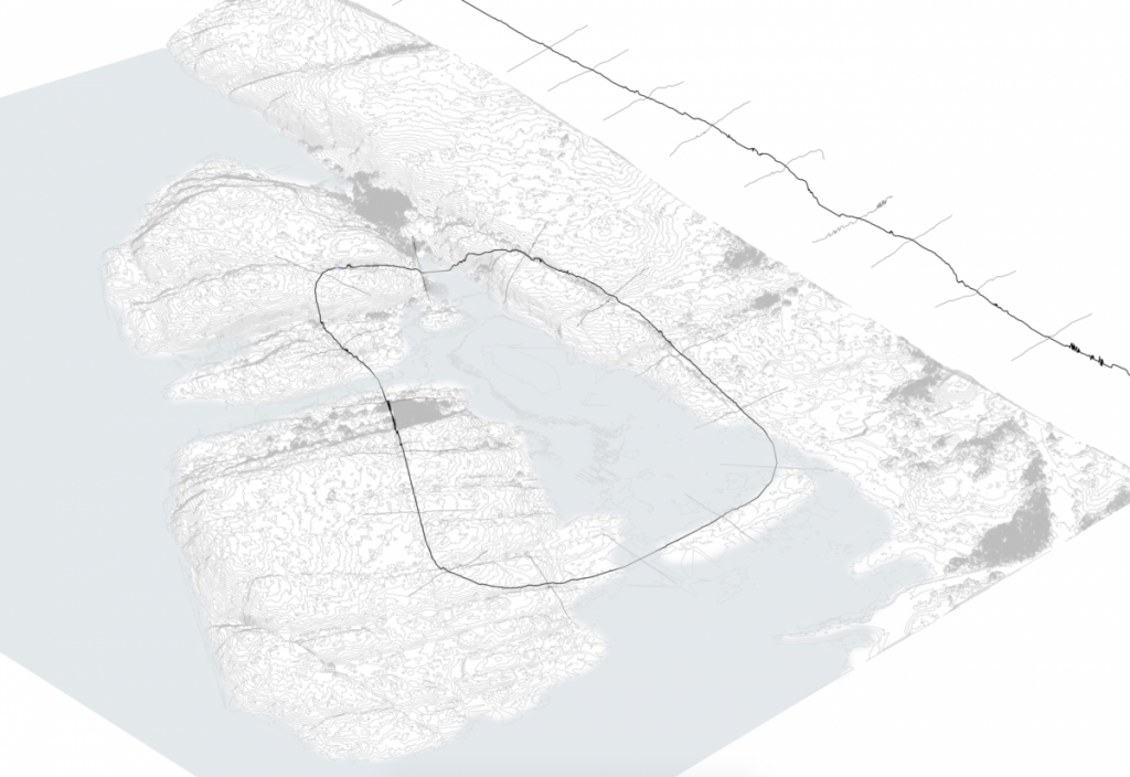
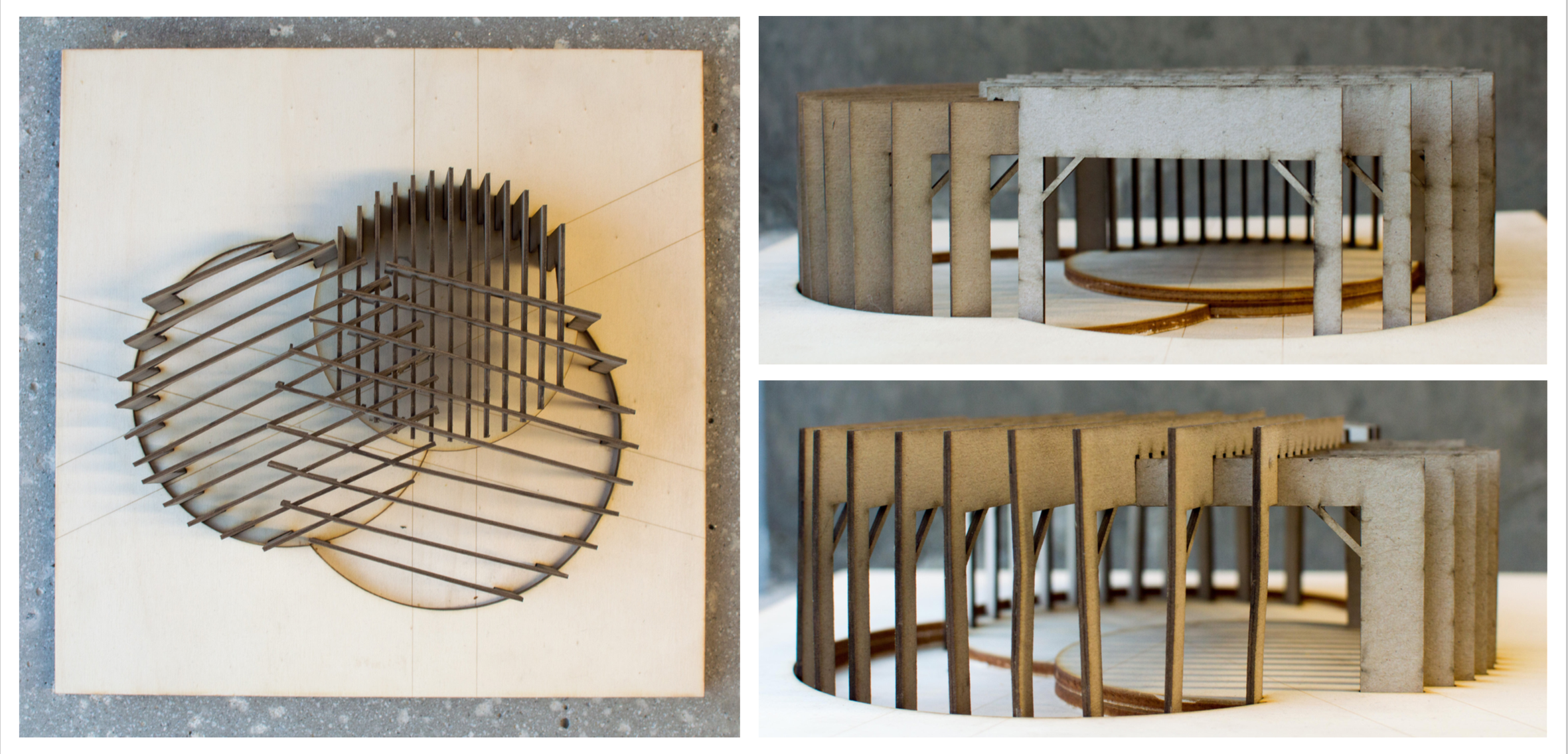
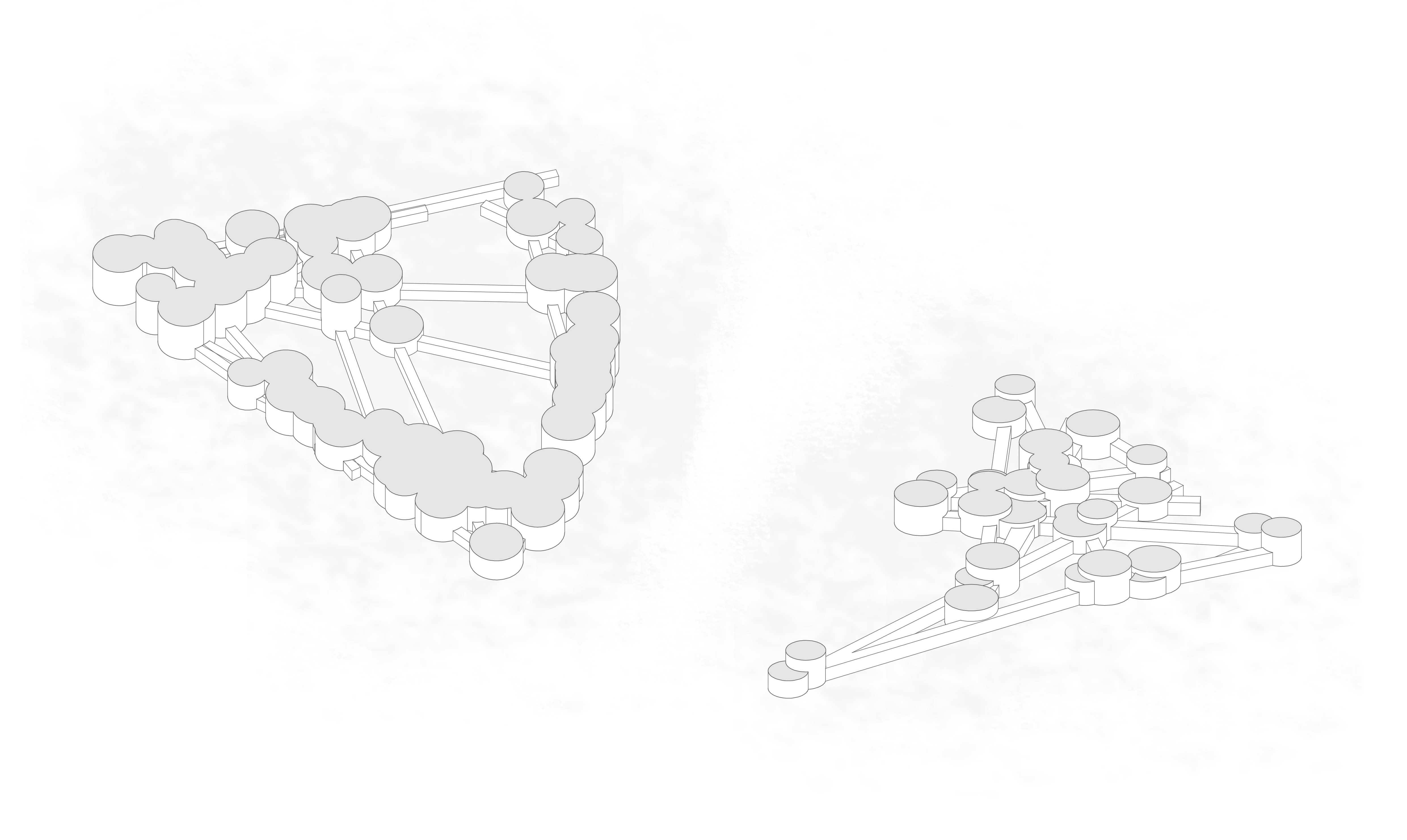
After these tests, I have re-introduced the path from project 3, and moved up to working at a larger scale.

Process

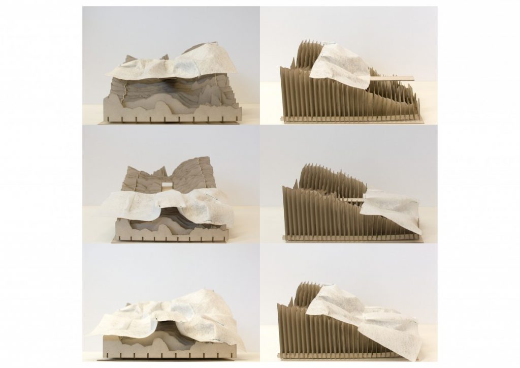
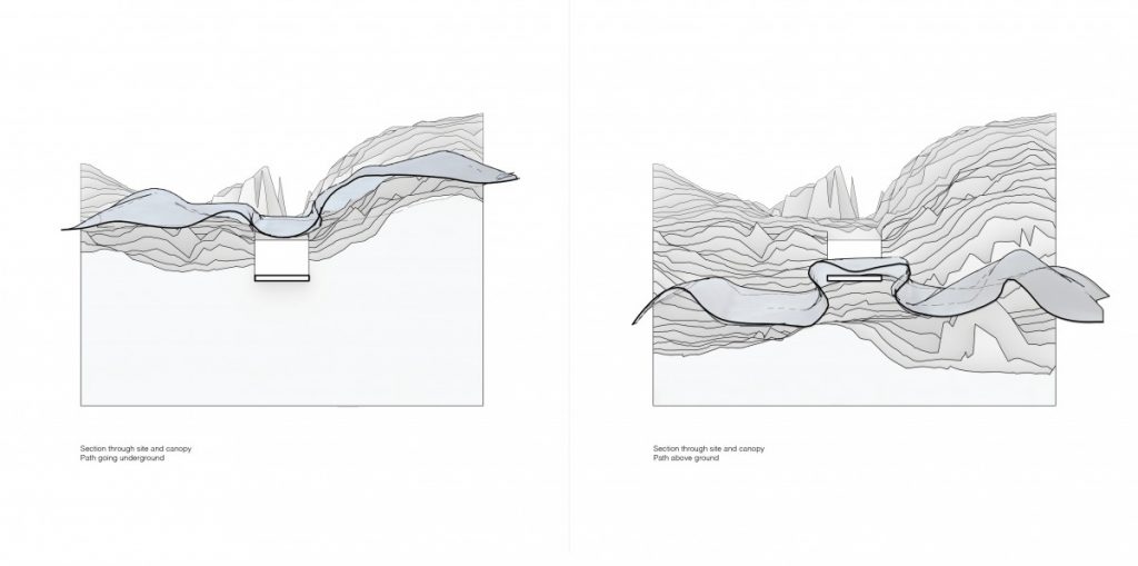
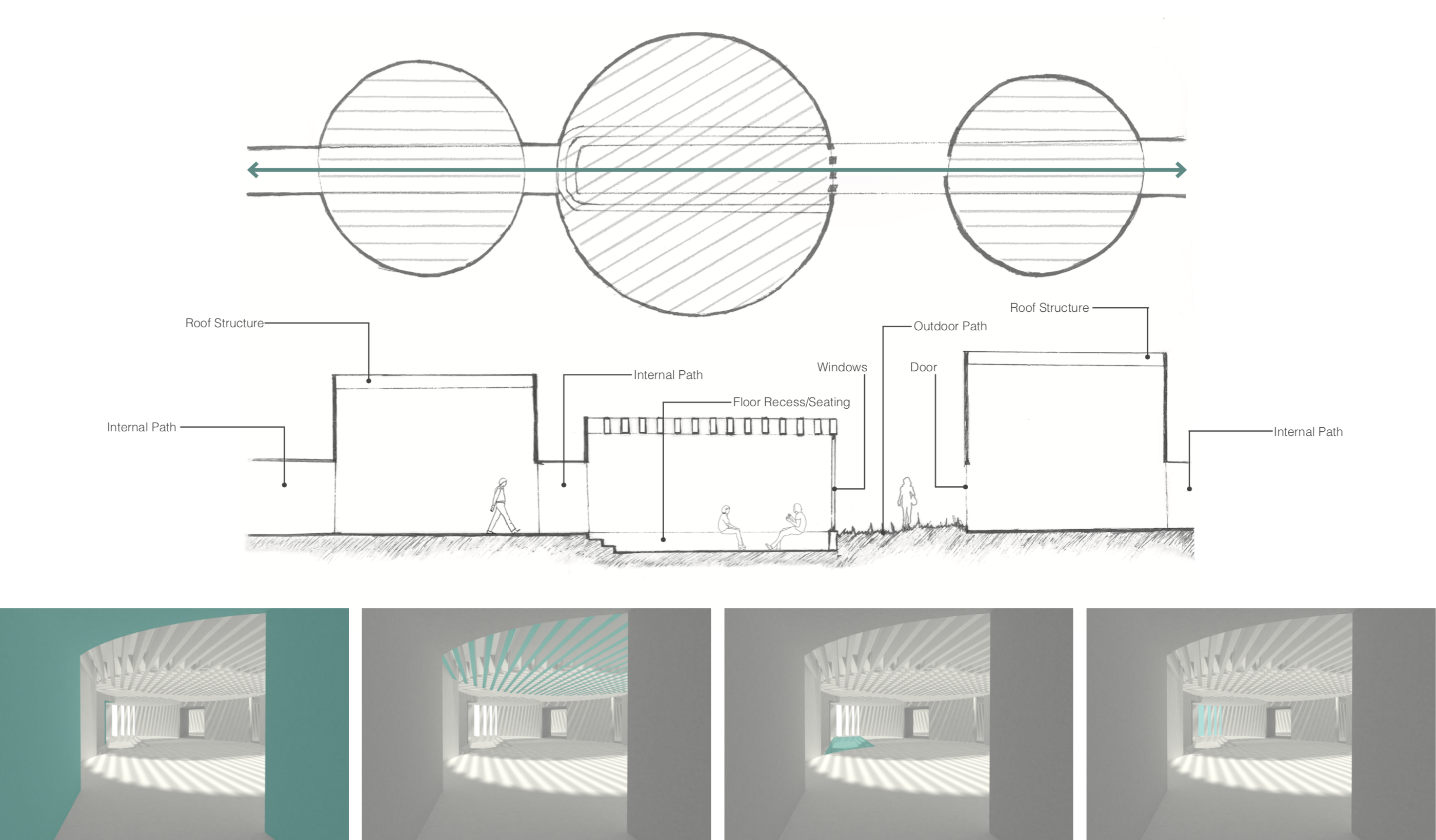
The two scenarios create different spaces, and their ‘patterns’ can be aligned and joined to create an interesting transition.

Pattern pieces separated
Pattern pieces joined
Generating support structures from folds

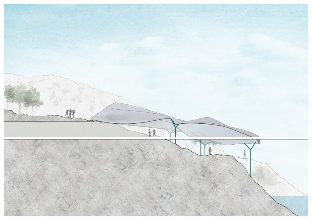
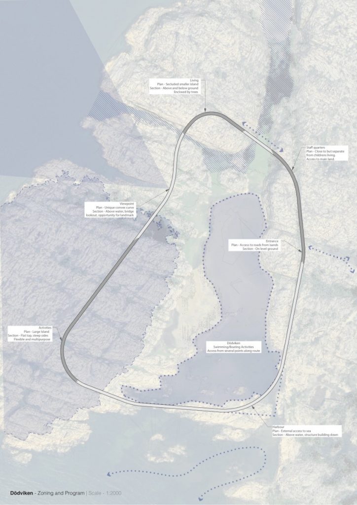
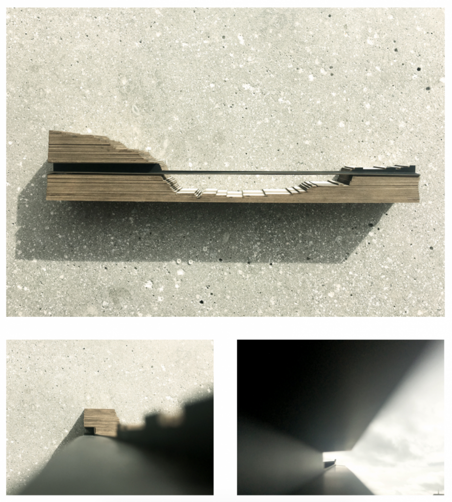
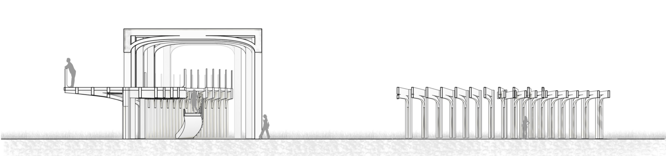
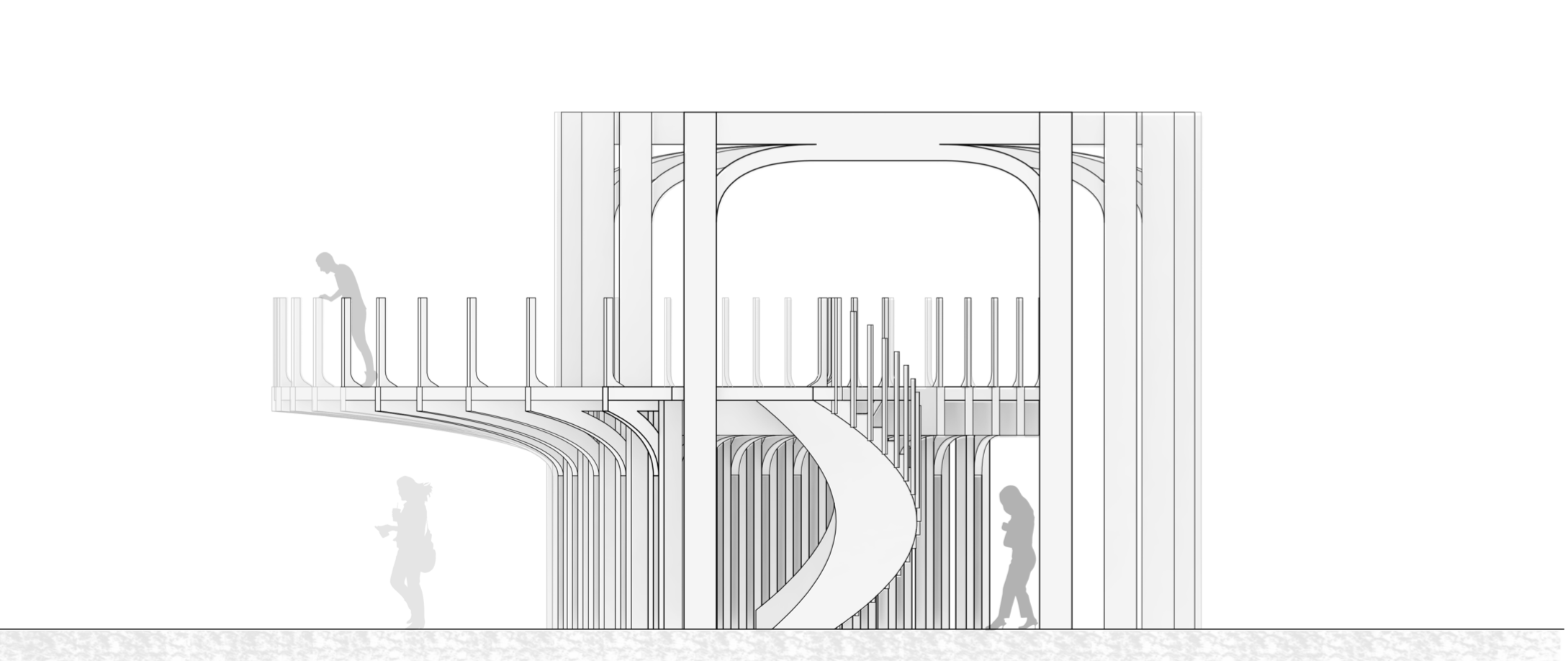
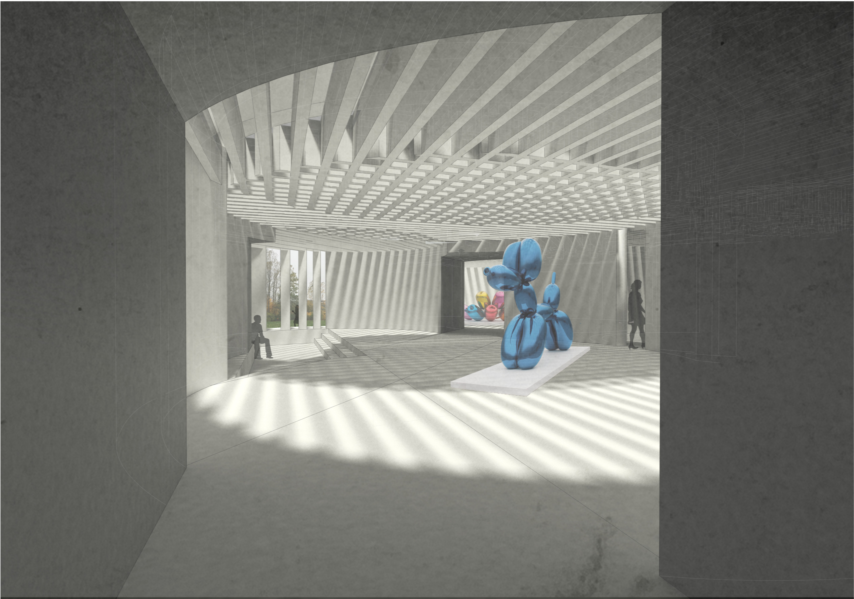
Stage one of the project resulted in a simple yet bold infrastructural loop connecting various elements of the campsite. Stage two created spaces by moulding and fitting a canopy to the site.

Wrapping it up

I took a step back and tried to more clearly explain how the path is generated, by breaking it down step by step. The fact that the curve is made up of lines and arcs gives me an opportunity to arrange elements of the program accordingly. Arcs would be “stops” along the path where things happen, and lines would form connections, both physical and infrastructural, between stops.

I have also continued to look at the spaces above and below the level of the path. This becomes clearer in this axonometric showing the path appearing and disappearing with the landscape.


By looking at the relationship between the plan and the section, and then the section and the plan, I have begun to analyse their characteristics and place elements of the program along the route. The section below shows the unwrapped route split into curved/straight and above/below segments, alongside the plan.

Here is a diagram attempting to explain certain elements of the campsite along the route.

More lines and circles!

Since the last post, I back tracked a little bit to refine and rationalise the ‘loop’ path. By analysing the steepness of this region in more detail, ridges in the rock are highlighted. I then traced these ridges and extended them to meet the next one, which formed a boundary. I took the inner region of these lines, and gave a fillet at the intersections. This loop is now a series of straight segments and arcs.

Rationalising the path | Plan of Dödviken

A benefit of building along ridges along the site is that it lowers the highest point along the route. This means that the path, which is at the average height of all the points it crosses, is lower. The bridges are a more reasonable height above the water, and the tunnels are at a more reasonable depth within the ground.

I would like to begin to analyse segments along the route for their materiality and geometry, both along the path and perpendicular to it. This can begin to form rules and inform the program of the camp.

Finally, this model shows a segment along the route where the path cuts through the rock as a tunnel, crosses over the water as a bridge, and continues over the ground as a path.

1:200 Sectional Model of Path

Oändlig slinga av Dödviken

After a brief look at the site and requirements of the brief, I set out 3 key criteria for selecting a location for the campsite:

  • Away from existing buildings
  • Interesting variations in topography
  • Close to water

By using the height map from Lantmäteriet to analyse steepness, and a plan of the island from Openstreetmaps, I was able to overlay this information and select a suitable site.

Height Map | Steepness Map | Buildings Map | Overlayed

The region that best fits my criteria is the land surrounding Dödviken, or the “Bay of Death”, on the North West corner of the island. A closer look at the geometry of this area shows that it is a cluster of islands that enclose an inlet of water- which could create a boundary and give the water a feeling of enclosure and privacy.

Site Selection

For this reason, I would like the core circulation of the camp to take the form of a loop- picking up on existing ridges in the landscape and crossing the water in the most feasible locations to create a continuous path around the water.

Creating a loop

By projecting this loop onto the site, and unfolding it into a straight section, I can start to analyse and populate the camp along this linear (but looping) path.

Unfolding the loop

The terrain varies quite dramatically across this route, both in altitude and type, crossing highs and lows, rock, trees and water. The idea is that this path be constant throughout the campsite, and provide access to the spaces and places along it which accordingly respond to the landscape. By taking the average altitude along the section for the path to sit along, it either takes the form of a bridge, tunnel, or just a path, depending on its context.

Vennation

Screen Shot 2018-12-17 at 14.25.40
Edge Conditions

Screen Shot 2018-12-17 at 14.26.56
Frame Spacing

Screen Shot 2018-12-17 at 14.27.17
Column Placement

Screen Shot 2018-12-17 at 14.27.35
Indoor/Outdoor Options

Screen Shot 2018-12-17 at 14.27.46
Frame Geometries

Screen Shot 2018-12-17 at 14.27.55
Generating Stairs

Screen Shot 2018-12-17 at 14.28.06
Timber Joint Studies


Screen Shot 2018-12-17 at 14.31.09
Process – Inputs

Screen Shot 2018-12-17 at 14.53.35
Plan

181212_exploded axo 100
Exploded Isometric

Screen Shot 2018-12-17 at 14.35.49
Perspective Section

Screen Shot 2018-12-17 at 14.36.01
Elevation

Screen Shot 2018-12-17 at 14.36.25
Model – 3 Indoor Spaces

Screen Shot 2018-12-17 at 14.36.46
Model – Support Geometry Tests

Screen Shot 2018-12-17 at 14.37.30
Model – 2 Indoor and 1 Outdoor Spaces

Light and Leading Lines

Looking into the Venn Diagram roof structure, it has several parameters that can be varied. The angle is defined by the direction of the path, however the spacing, thickness and depth of the beams can be varied to achieve a certain level of light, or a certain atmosphere in the space below. By using Grasshopper the parameters can be quickly tested.  

Screen Shot 2018-10-29 at 21.57.47

This set of 3D printed models of the roof system keeps one circle constant while changing one parameter in the other circle. This shows the difference in the shadow effect, and how the appearance of the overlapping area changes. (Scale – 1:200)

Screen Shot 2018-10-29 at 21.57.56

In this model, at a larger scale (1:100), I am investigating a more complex Venn diagram with three intersecting circles. By varying all three parameters in each circle, the different levels of lighting can be observed in the shadows. 

Screen Shot 2018-10-29 at 21.58.14

The paths that generate the spaces provide more opportunity to express themselves. As they travel across the boundary, they can take the form of indoor and outdoor paths, windows, roof structure and ground level features such as steps or seating:

Screen Shot 2018-10-29 at 21.58.26Screen Shot 2018-10-29 at 21.58.42

The Parametric Venn Diagram

Since the last task, I had a look at re-ordering the code so that the circles are extruded first, and then performing a boolean on the cylinders. This has the benefit of more variety in the heights of the rooms, and more interesting 3D intersections.

1_extrusions.png

Looking back at the site, I chose a boundary that had multiple paths leading into it, with the idea that when wandering along the site one can wander in and out of the konsthall. The generated paths are a combination of internal corridors and external paths, providing a sheltered route as well as the option to move outdoors between the clusters, like paths through the park.

2_Plan

The circles, which are still clearly visible in plan, provide an opportunity to further express the direction of the paths that generate them. By adding a linear structure to the roof, following the direction of one of the paths, a simple but interesting ceiling is created. Where the circles overlap, it creates a more intricate lattice.

3_Venn Diagrams

The alignment of the roof structure makes the paths even more legible, and the roof provides an opportunity to bring natural light into the spaces.

4_Axo

Some lines, and some circles…

When looking at configurations of precedents, I found two aspects particularly interesting. One was the direct, linear spaces that appear as occupied pathways, and the other is the overlapping of simple geometries to create a dynamic form.

180915_Configuration Examples

I feel like the first one is a missed opportunity for some interest or excitement in locations where these paths meet. I began by working with a simple box boundary, dividing the boundary into points and connecting them. These then cross over each other, and I have added circles at the intersections.

180925_output

By randomising these circles, cleaning up the overlap and forming paths out of the lines, I have created a configuration, which can then be applied to any boundary curve. In 3D, it starts to form something like this:

180925_output

And finally, an example on site:

180921_site file