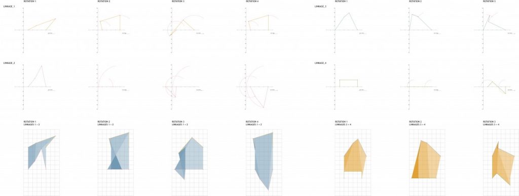
As we moved onto task 2, I started analysing forms of the linkages and combining two sets to test the spatial properties they exhibited.
The rotation of the linkages needed to exhibit some form or motion and resulting change that would offer a variation in form and surface and space, as in the previous study of the kaleidocycle.
The servo was mounted to a clear acrylic frame and I began to run tests of forms using the basic principle of the four bar linkage.
As observed from the tests above, the spatial study extended only to planar elements. I began incorporating rotation and folds to allow for movement in 3 dimensions and multiple axis for each linkage. Both sets of studies provide grounds for further exploration but I will need to be more intentional in the variation of parameters of the subject.
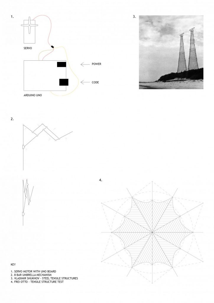
Project 04 saw a move to material prototyping and developing a methodology for building three dimensional forms. I looked into Frei Ottos fabric tensile structures as well as engineer Vladimir Shukhovs steel tensile structures as precedent.
Keeping the automated robotic theme running I also decided to incorporate a servo motor into my design process. This brought a moving element to the prototyping and prompted the research into the umbrella mechanism and three/ four point linkages.
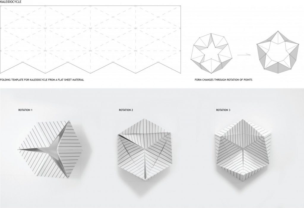
I also explored the Kaleidocycle (flexagon) which are models of linked tetrahedra which turn through their centres. I wanted to incorporate these methods for materials that, through their connection, could change form and produce multiple spatial environments.
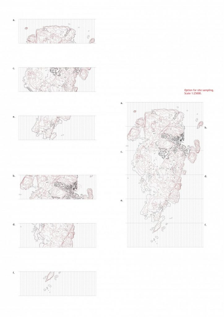
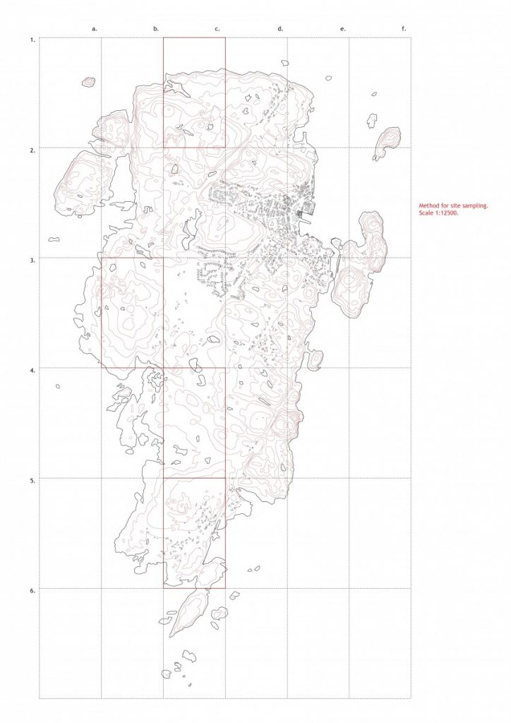
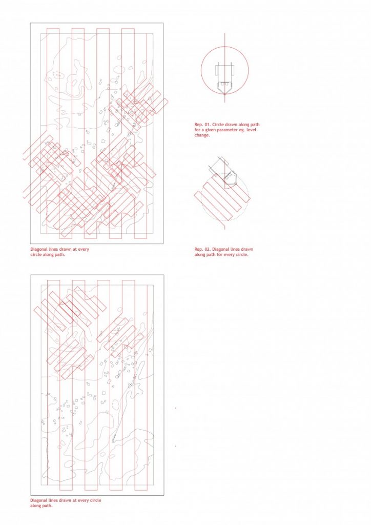
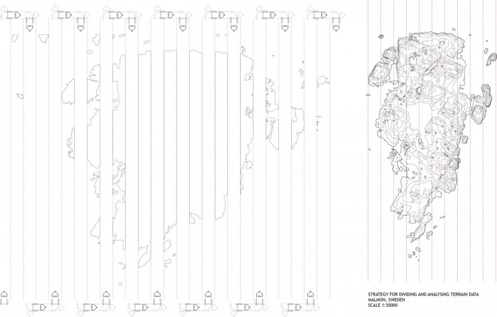
Moving on from the last pin-up I needed a better management strategy for the site data. When the robot reads and responds to the site it needs to be at a scale that the data is useable and realistic for the architectural design to be implemented. Providing a grid system allowed a reading of the entire terrain in greater detail where each grid tile can be blown up and analysed. Consideration was also taken for the dimensions of a manageable testing area for repeated demonstrations and data collection. Below are two possible methods of grid reading of the site. The maps were sampled at 1:500 scale with the second method of grid division.
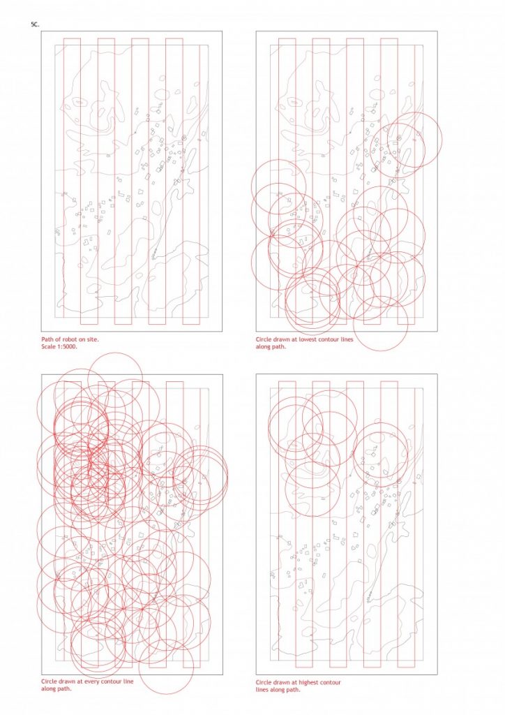
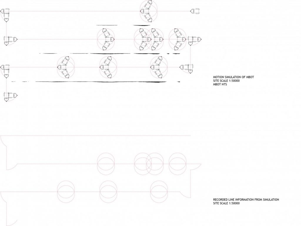
The robot has a narrow range of testing limited to its line and ultrasonic sensors. This provides a linear path of testing at 1cm intervals on the sample map which would be every 50metres in real life. This gives a dimension and scale to any output that will be collected. In the simulation drawings, the robot is to respond to the changes in height at any level changes, changes at the highest and lowest areas. The output is a full 360 rotation of the robot leaving circles as the response. The robot is allowed to respond to its generated data again and draw diagonal lines at a 45 degree angle at every circle. This then gives a criss cross of linear data that the building system of precast members could be assembled upon.
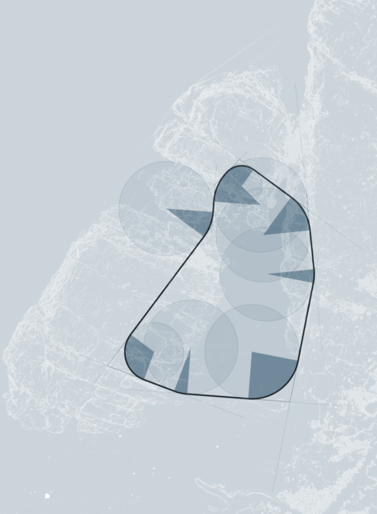
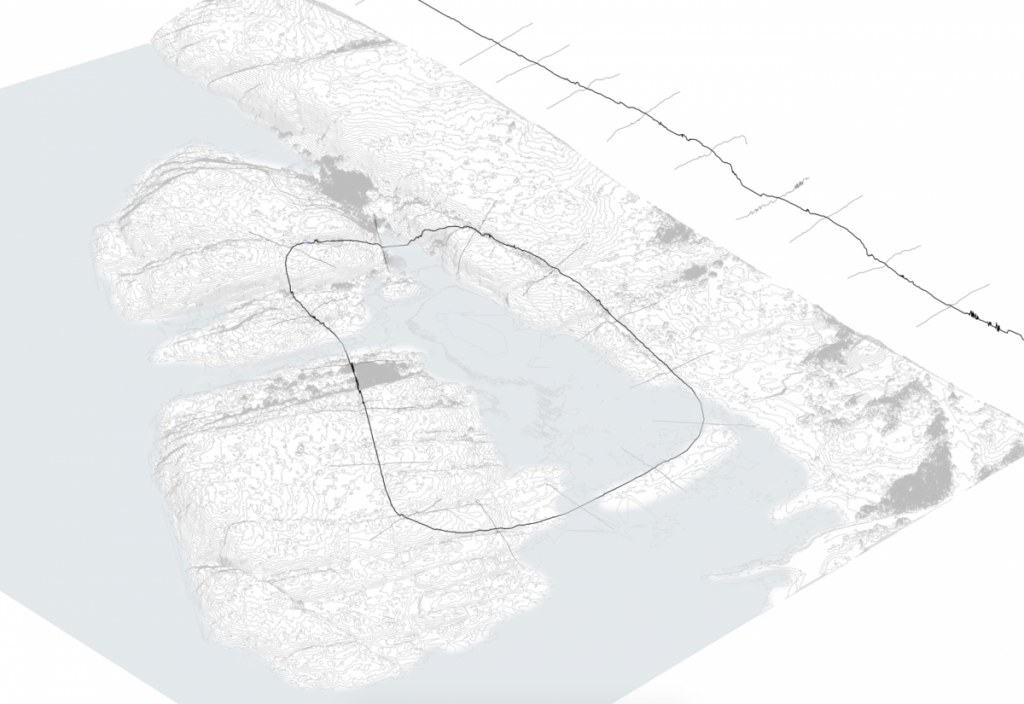
Since the last post, I back tracked a little bit to refine and rationalise the ‘loop’ path. By analysing the steepness of this region in more detail, ridges in the rock are highlighted. I then traced these ridges and extended them to meet the next one, which formed a boundary. I took the inner region of these lines, and gave a fillet at the intersections. This loop is now a series of straight segments and arcs.
Rationalising the path | Plan of Dödviken
A benefit of building along ridges along the site is that it lowers the highest point along the route. This means that the path, which is at the average height of all the points it crosses, is lower. The bridges are a more reasonable height above the water, and the tunnels are at a more reasonable depth within the ground.
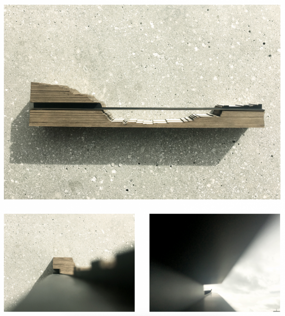
I would like to begin to analyse segments along the route for their materiality and geometry, both along the path and perpendicular to it. This can begin to form rules and inform the program of the camp.
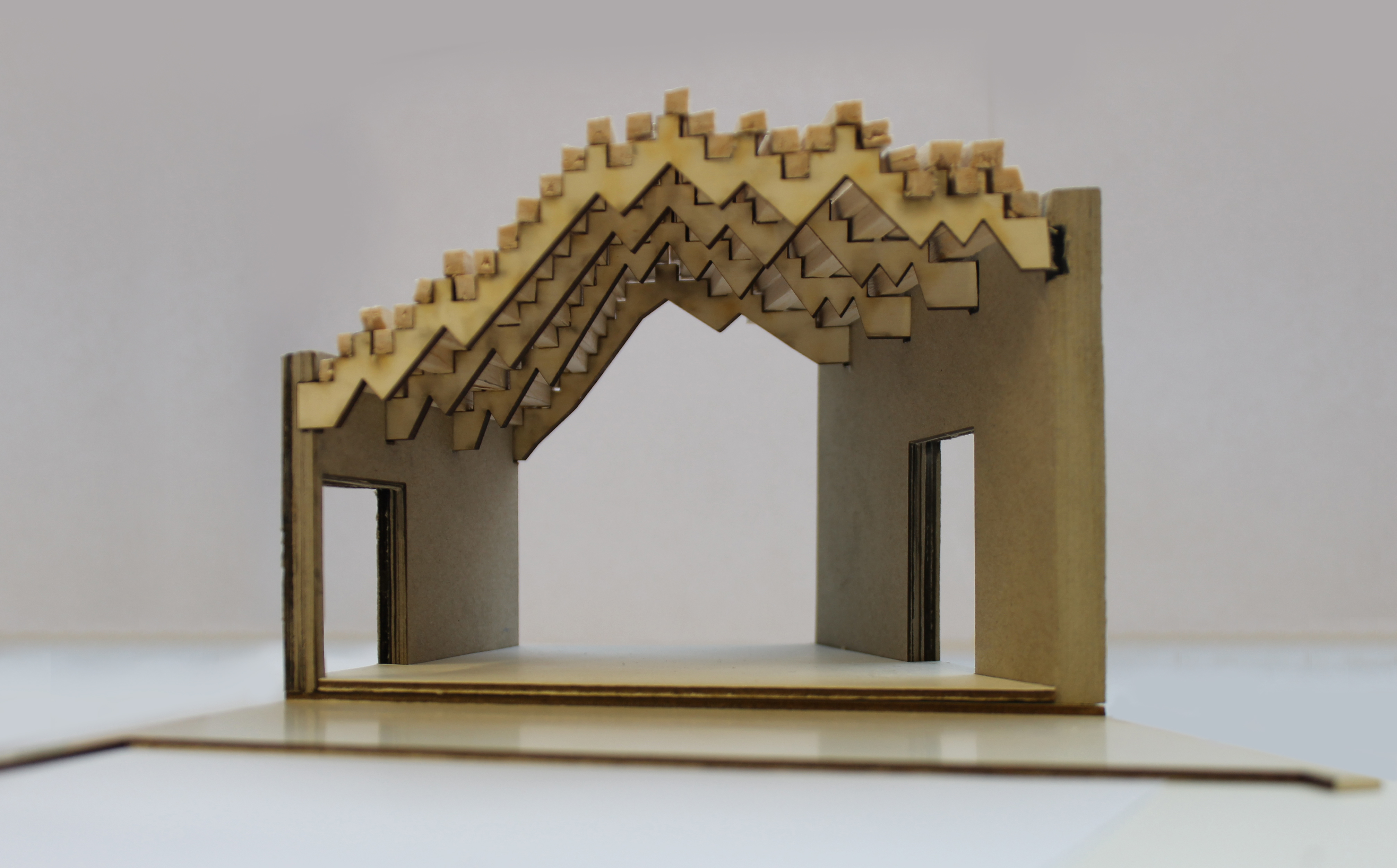
Finally, this model shows a segment along the route where the path cuts through the rock as a tunnel, crosses over the water as a bridge, and continues over the ground as a path.
The robot allows for direct feedback for the design strategy proposal. In oder to fully apply this method of working I formulated a strategy for the summer camp as an initial system of production, construction and form to allow for freedom in testing.
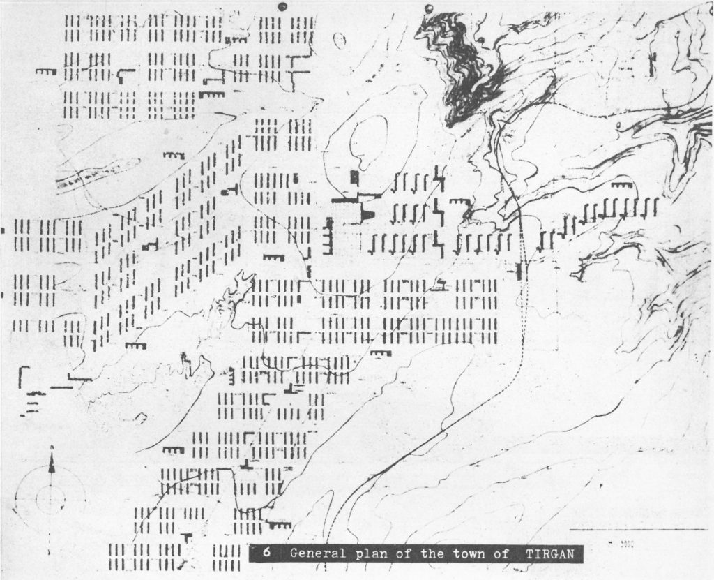
I took the soviet architectural town planning in 1930 by E. May as precedent. The linear markings on the site appears to respond to the context yet also offer an abstract notation of the program of development. The summer camp proposal for Malmon will be about setting up a grid that will be the groundwork for precast members that can easily be assembled and disassembled. Concepts of sustainability and impermanence are suggested.
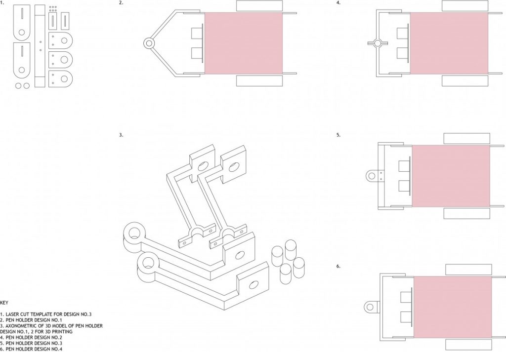
To obtain an output from the robot I 3D printed a set of arms/ pen holders to obtain a line drawing from the site analysis. While the robot scans the site, It would produce a line drawing as a data output. The implementation was dictated by the robots sensors, size and my coding capabilities. I did not achieve an outcome that could be presented or represented the idea. For the final task in this project I will work towards focusing on what data I want as an output and a much simpler application of the robots abilities.
Studio 9_Project 3_Task 2: Occupations and Interventions.
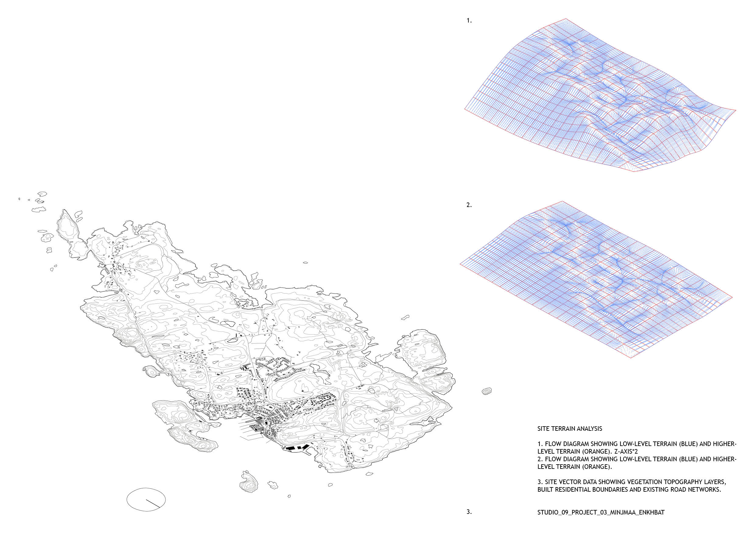
To occupy the site I began by collecting and analysing site data for Malmön. The program QGIS for editing and analysing geospatial information was used to extract the vector information; topography, population and marine geology. A colour png map provided the basis for extracting the 3D terrain data using a python script and into Rhino, with initial topography analysis through flow diagrams in grasshopper. A photographic study was also carried out and compiled into a booklet.
The intervention aspect was based heavily on ABM research – agent based models. An agent is aware of its surroundings and its abilities. When acting in a collective manner they exhibit swarm intelligence, the collective behaviour of decentralised self-organised systems. This means each member autonomously offers its abilities in order to study an overall system. The members, or agents, self-coordinates without a leader and cooperate in solidarity resulting in a self-healing system. This allows members to be added or removed dynamically as the agents will recalibrate in a constant feedback loop.
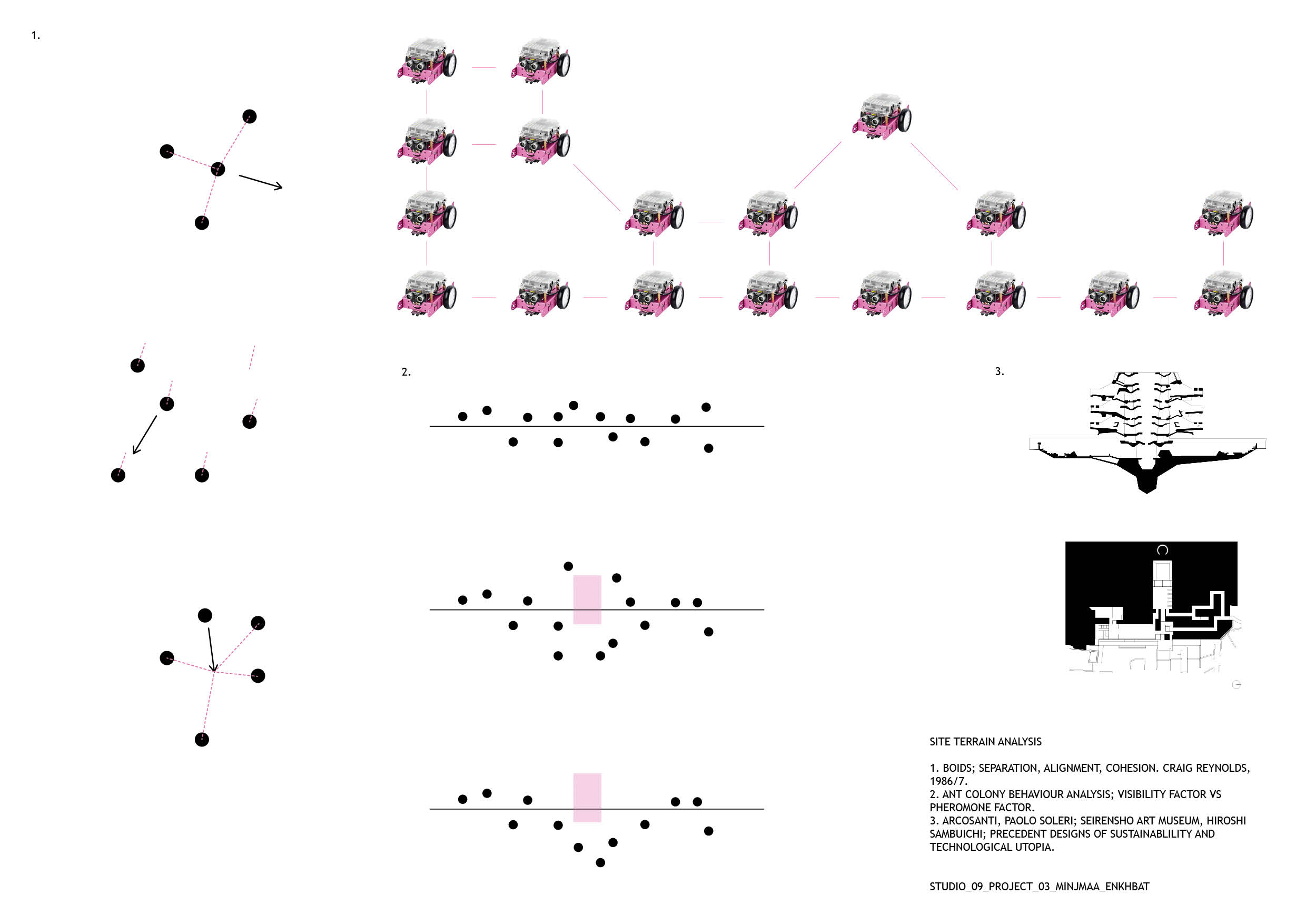
‘Boids’ by Craig Reynolds was the grounds for my research into swarms and flocking behaviours for computer simulations. His theory is a basic flocking model consisting of three steering behaviours; separation, alignment and cohesion. Ant colonies that organise using pheromone and visibility factors were also part of the initial studies.
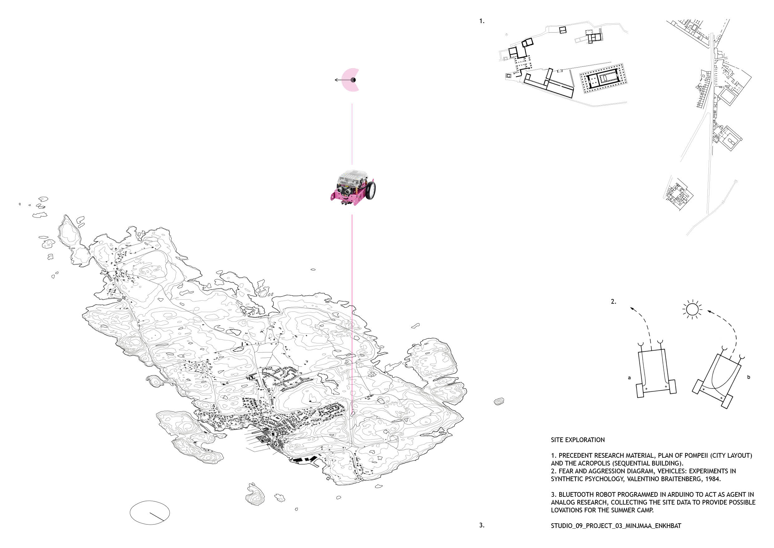
I would like to base project 3 on the collection of site data using agents and subsequently allowing the agents to alter the collected data in order to intervene and implement the summer camp design on Malmön. To engage with this theory in the material dimension, I decided give form to the agent as a mini Arduino robot name Mö. This allows for real-time feedback with the tests I run for the agent simulation on site. Giving robotics agent behaviours has its own research and theory basis. Although Craig Reynolds theory of Boids is a great foundation, I also studied vehicle behaviour and coding in ‘Vehicles: Experiments in Synthetic Psychology’ by Valentino Braitenberg. Processing and Arduino will be the main programming softwares, with C and Java as scripting languages. The Nature of Code on youtube and Github, as well as Studio 09’s own processing tutorials have been great learning platforms for this.
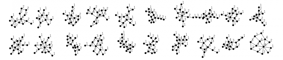
The 9 projects below were collected as precedents for project 3.
These plans and sections are a representation of two strings of thought; i. an exploration of form and approaches to setting; ii. city making and sequential building. The first set of projects play with ideas of control, vistas and the act of an icon in the landscape. They tackle form and building materials in an experimental manner using the environment and new technology as key tools. A simple question of building up or down and along the terrain is also brought to question. The second string of thought is concerned with city making and sequential building with studies of the layout of the city of Pompeii, the Acropolis of Athens and futuristic plug-in cities.
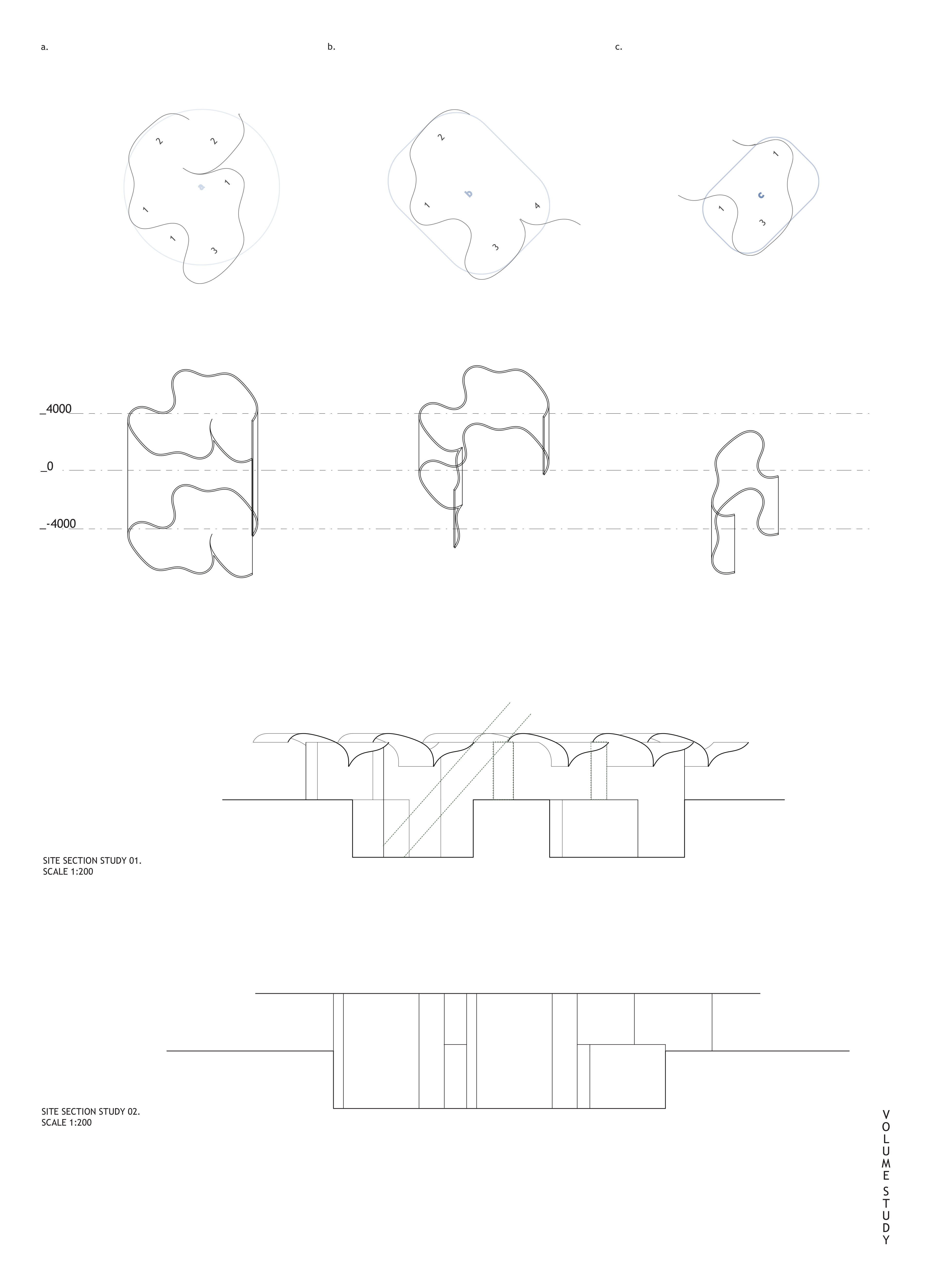
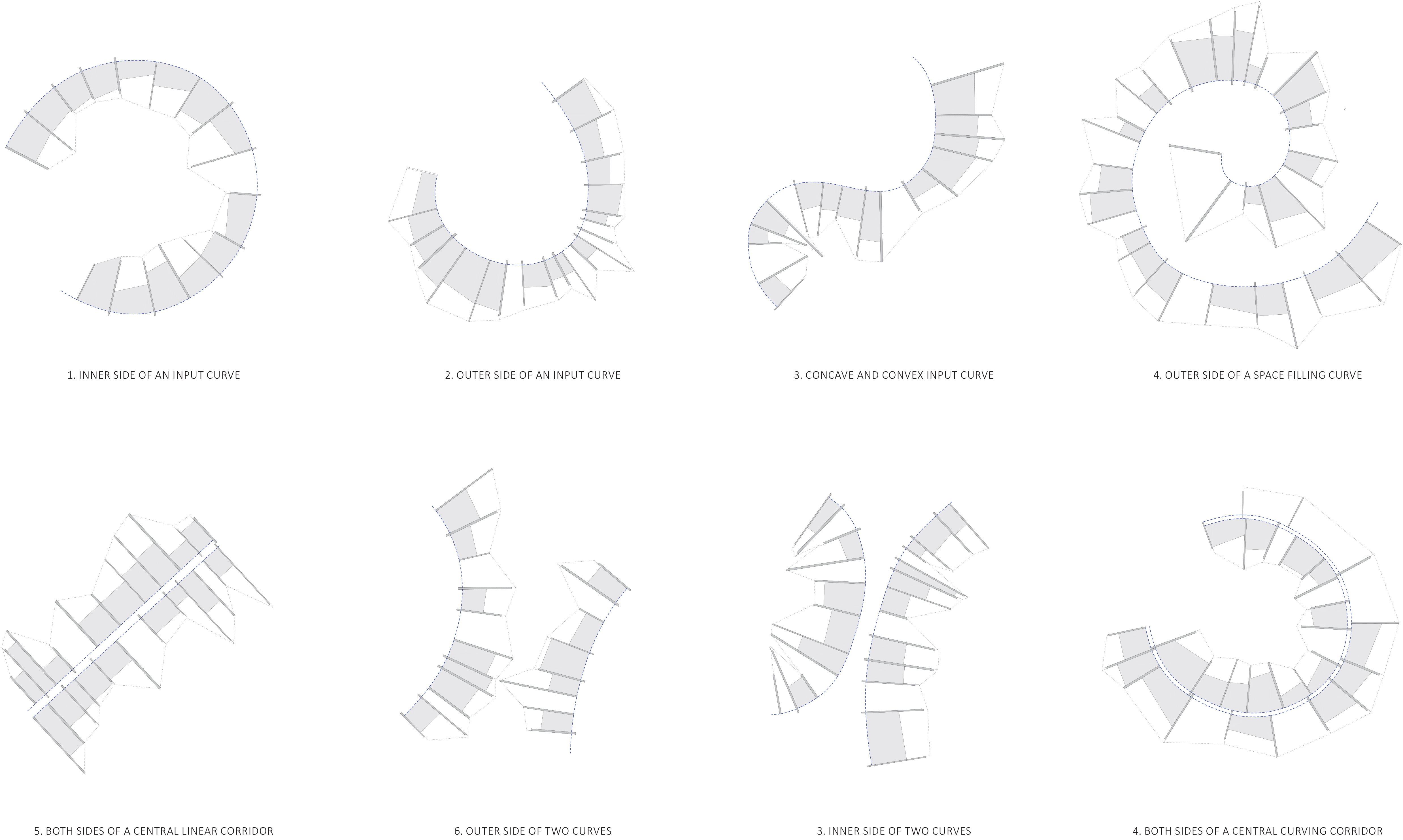
After experimenting with a range of different input curves to see the different outcomes produced, I began to analyse the different types of spaces produced depending on the magnitude and type of curvature. From this I classified 5 different situations below, and started to visualise how the differing geometries affected the views within the spaces, the views out, and the conditions of the spaces.
From this I selected three of these conditions and started to explore the materiality and thickness of the spaces. I became interested in forced perspective and how I could apply this to the generated spaces to make shallow spaces feel deeper and vice versa. But also distort and effect the users experience of the space in different ways.
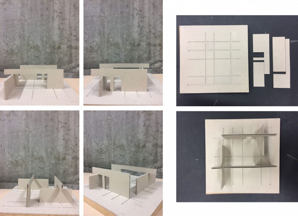
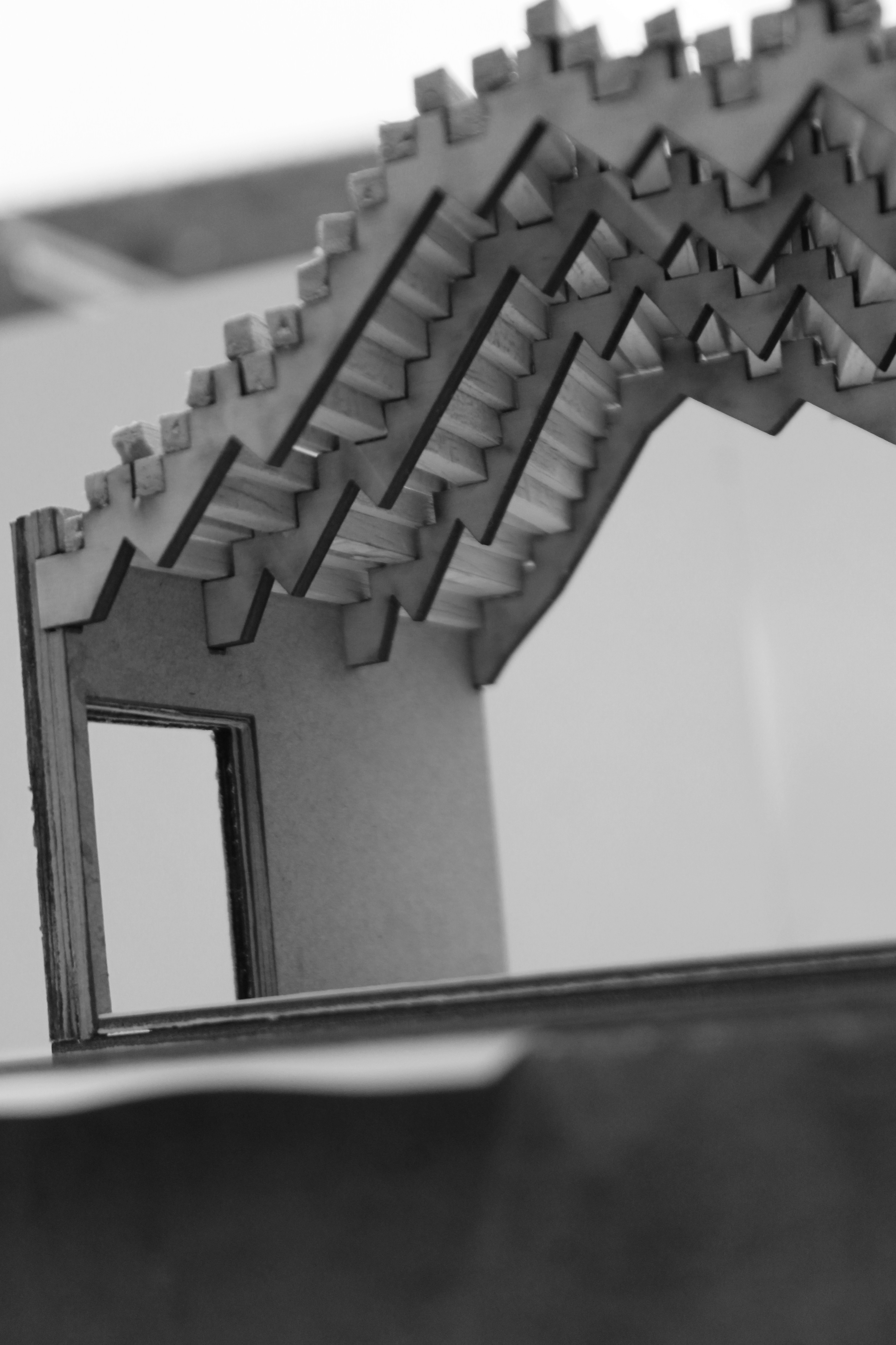
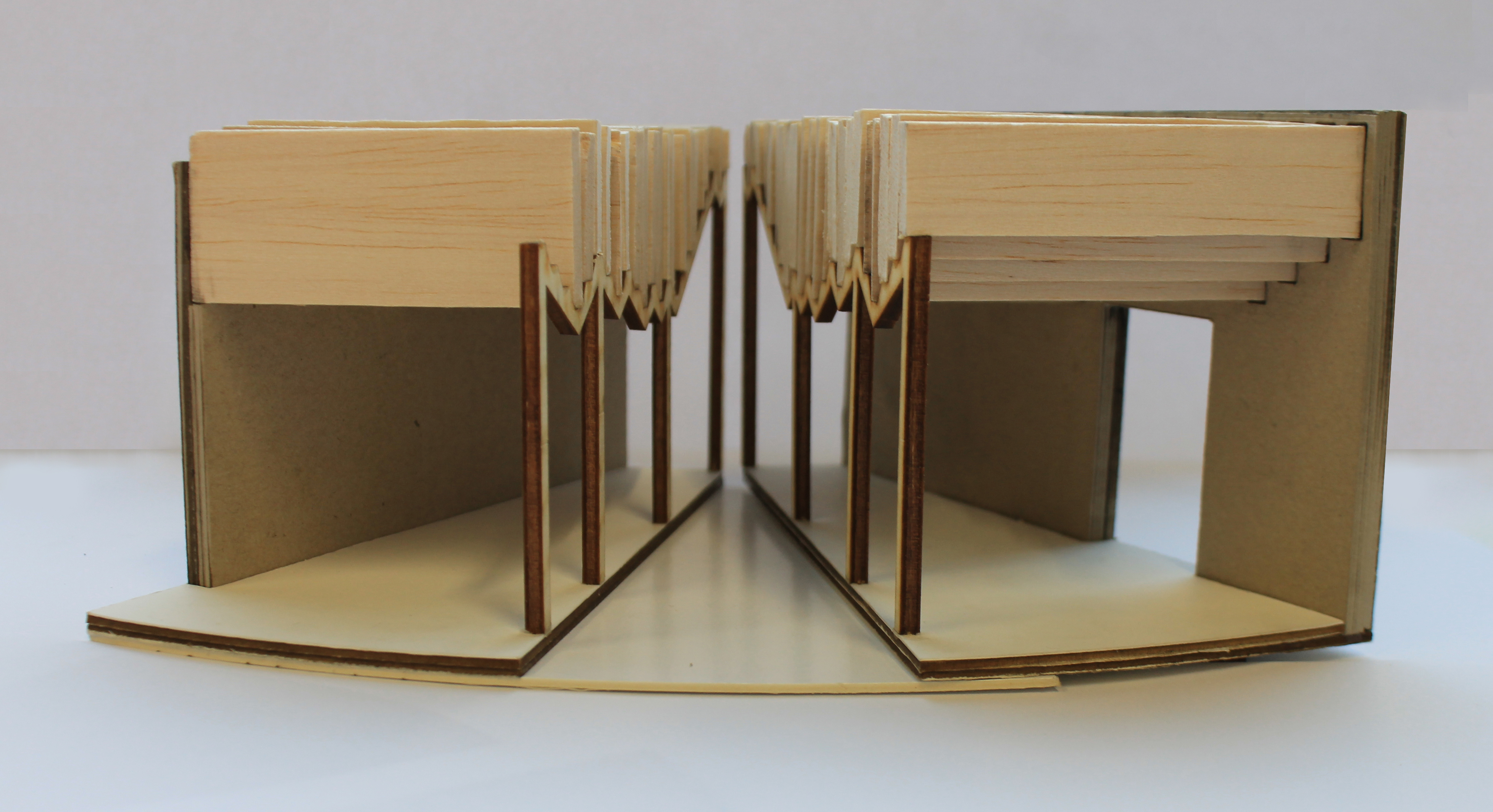
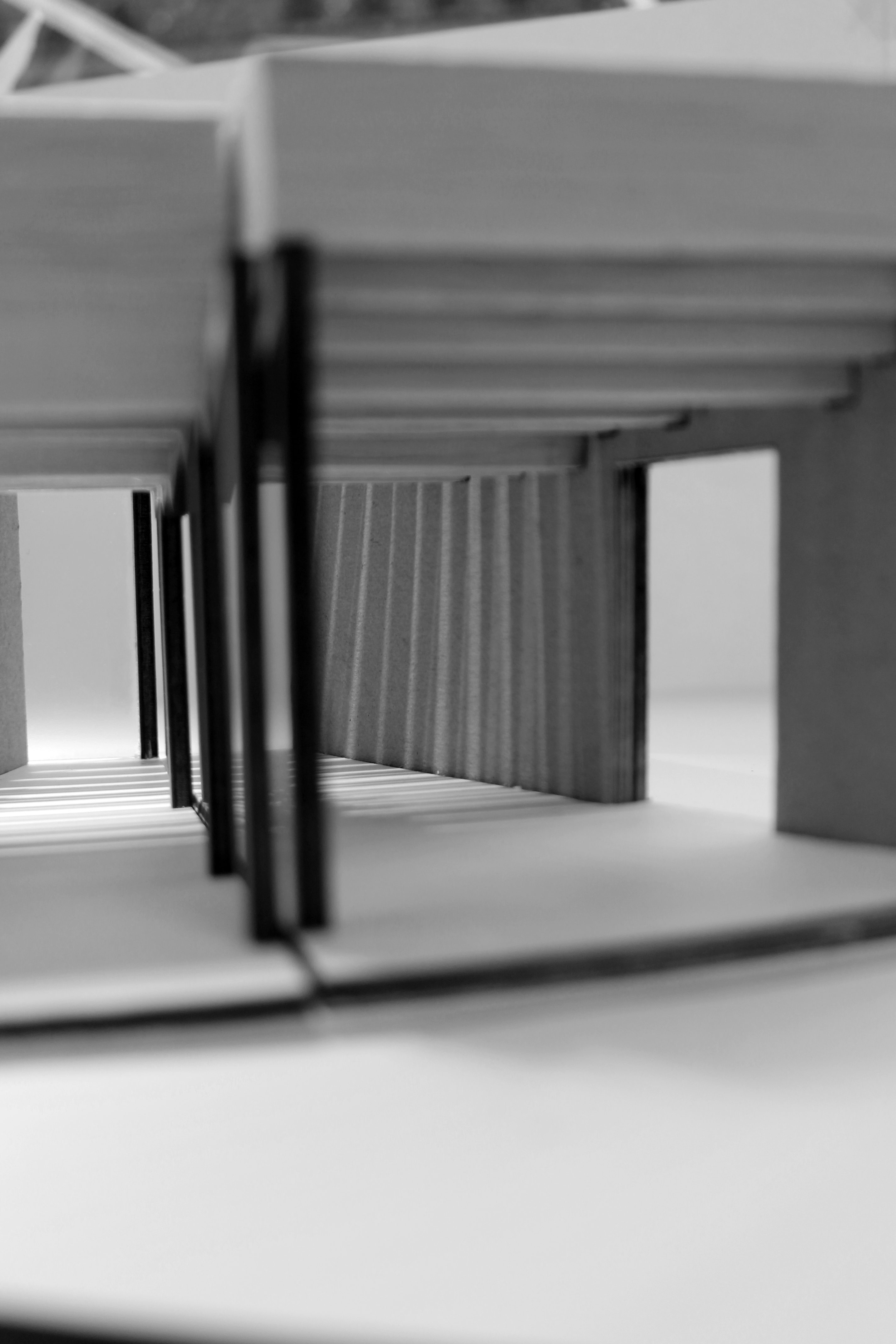
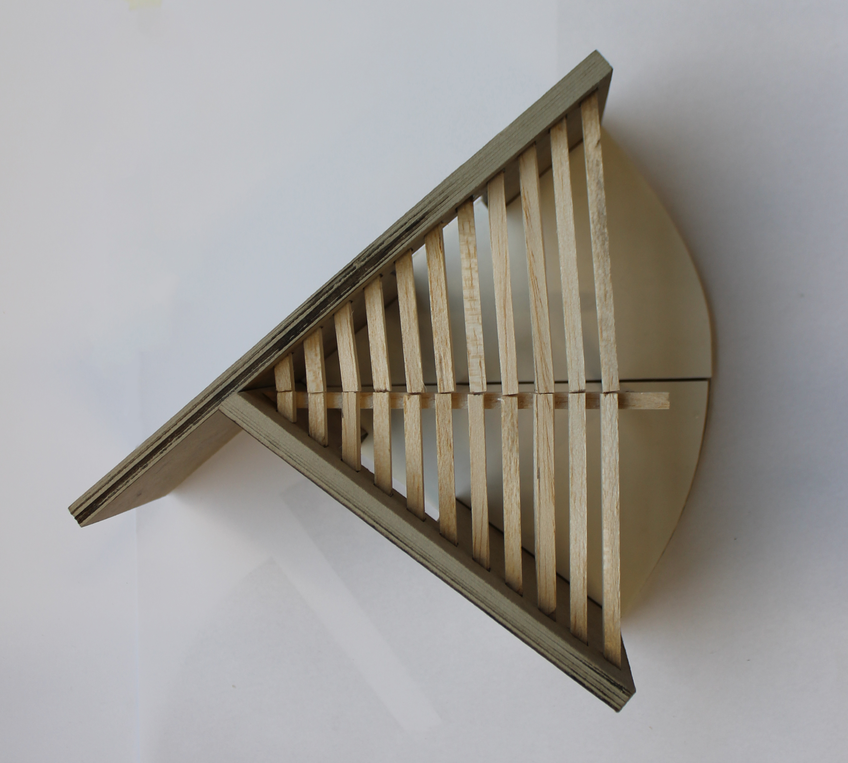
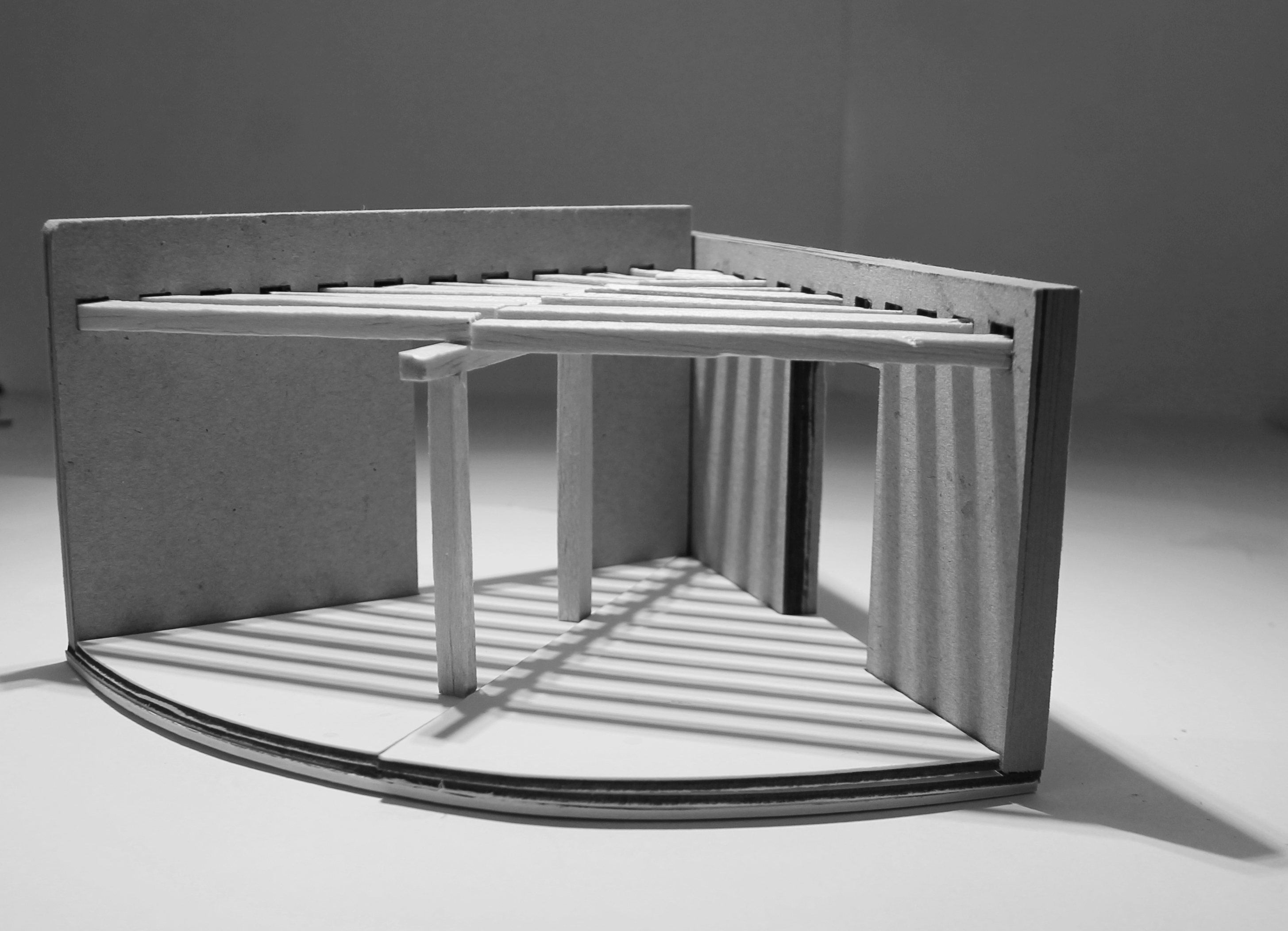
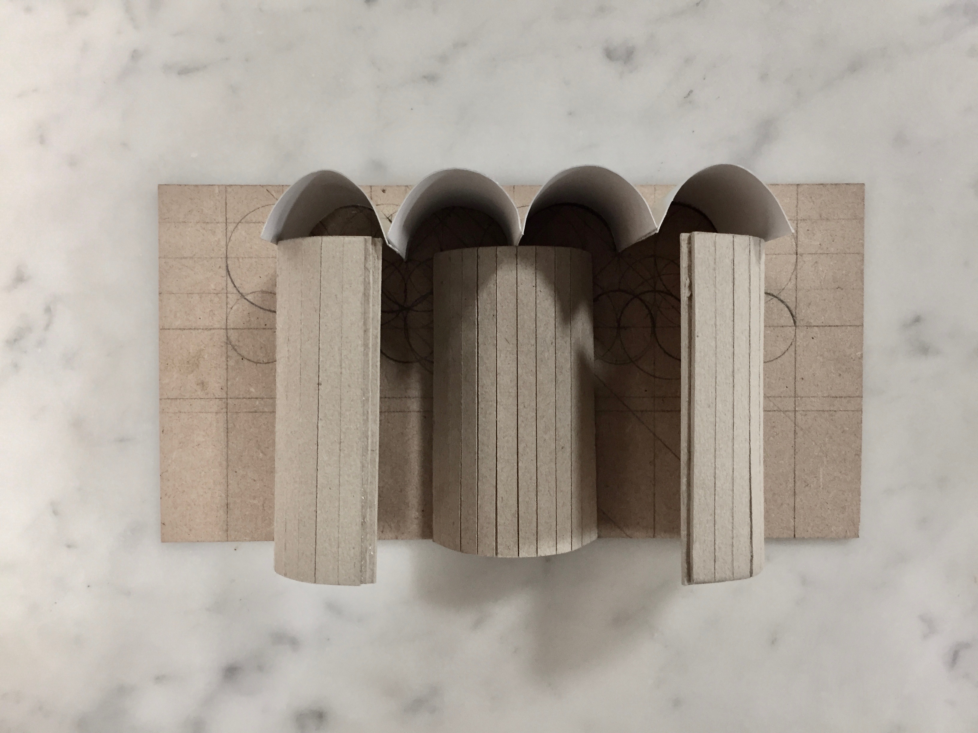
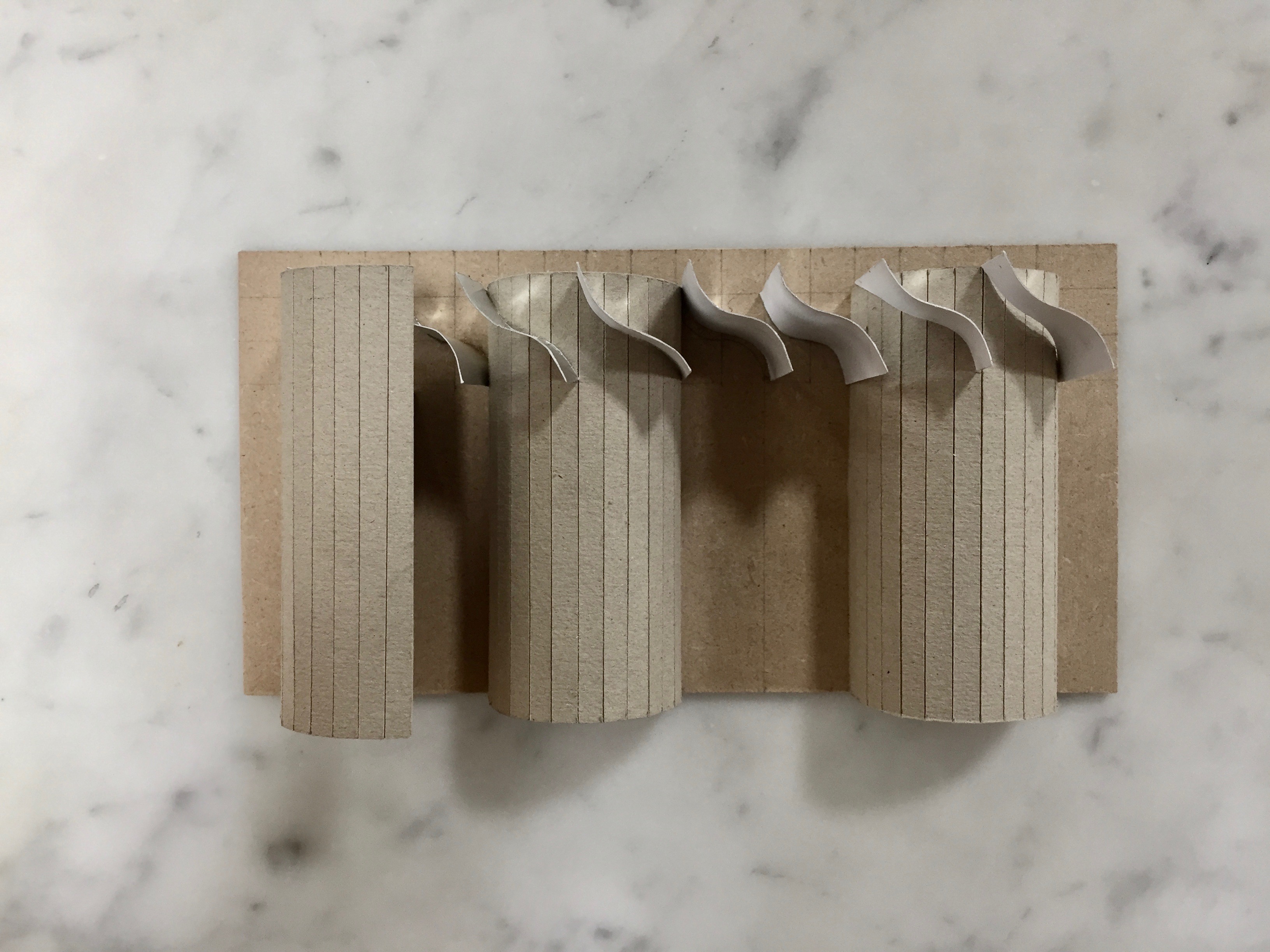
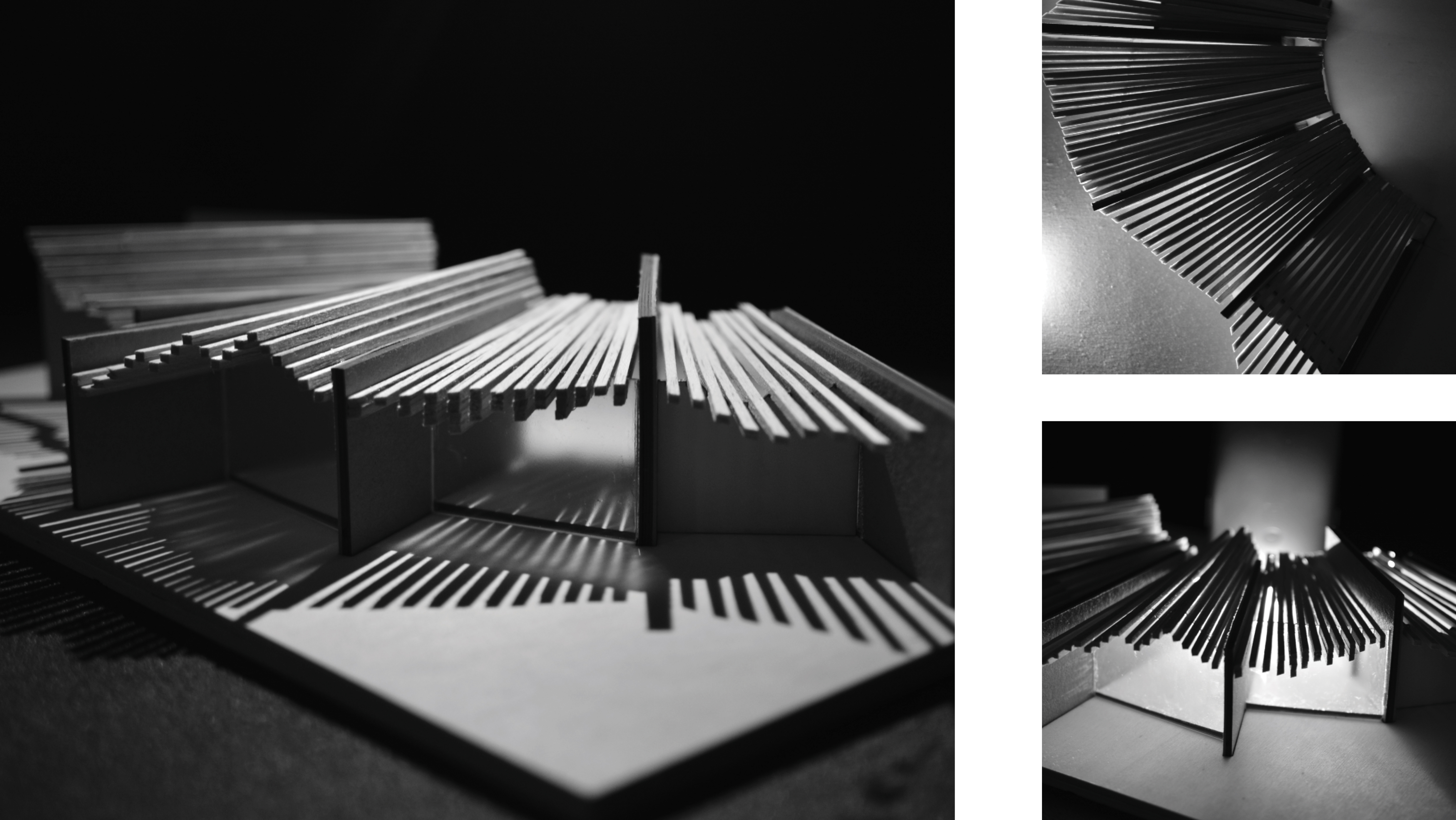
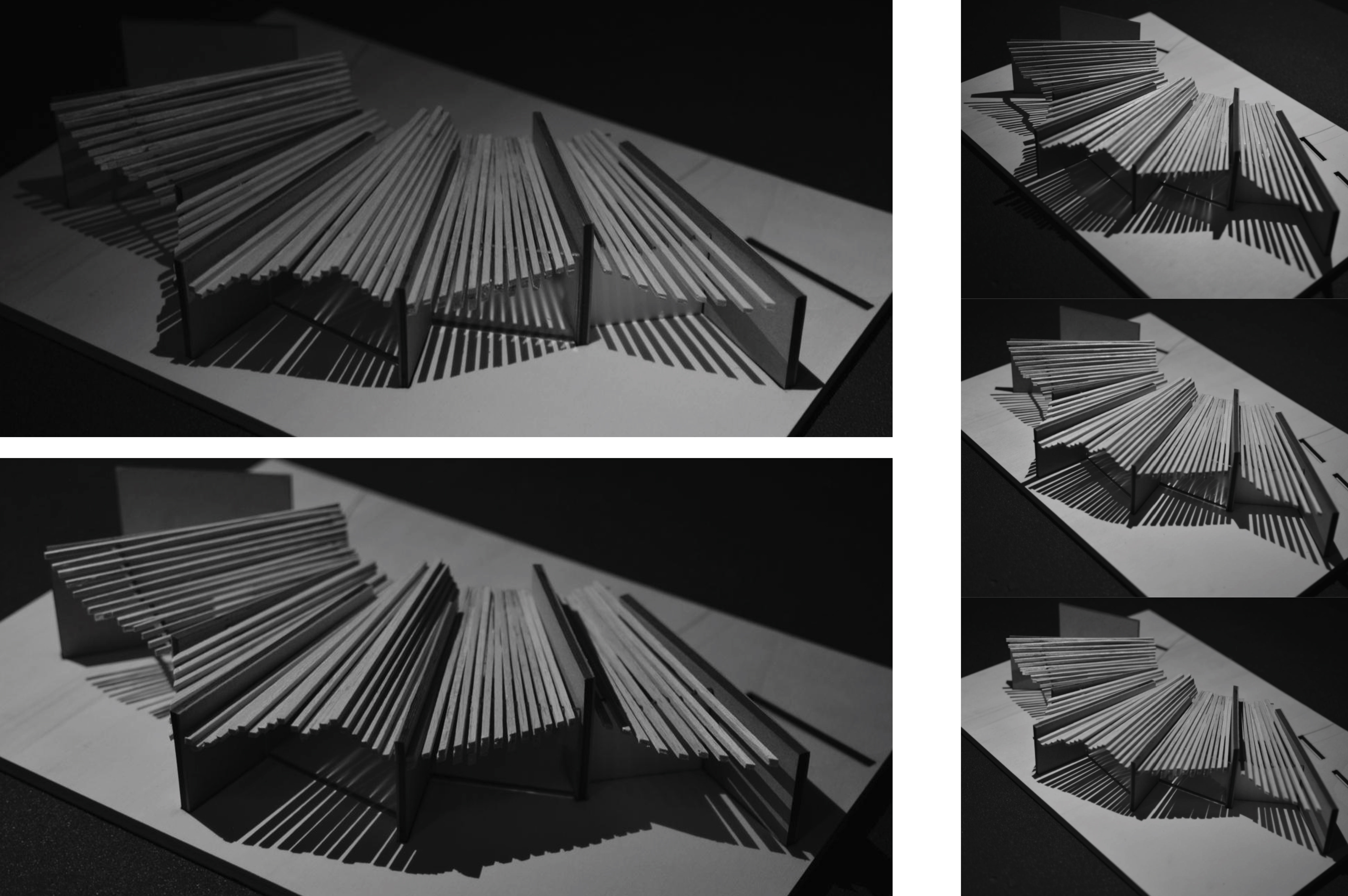
Within the three sectional models below, I explored both in section and perspective. Looking in section at how the beams and and roof could connect and sit within the walls, but also how the spacing could change to play with forced perspective. Then the sectional models would be combined to allow myself to visualise the views within the spaces and the views out from them. I took a step back from the previous model where I was looking at a continuous roof system and looked at each of the 3 modules individually to look at different ways I could structure the roofscape and play with the lighting of the spaces.
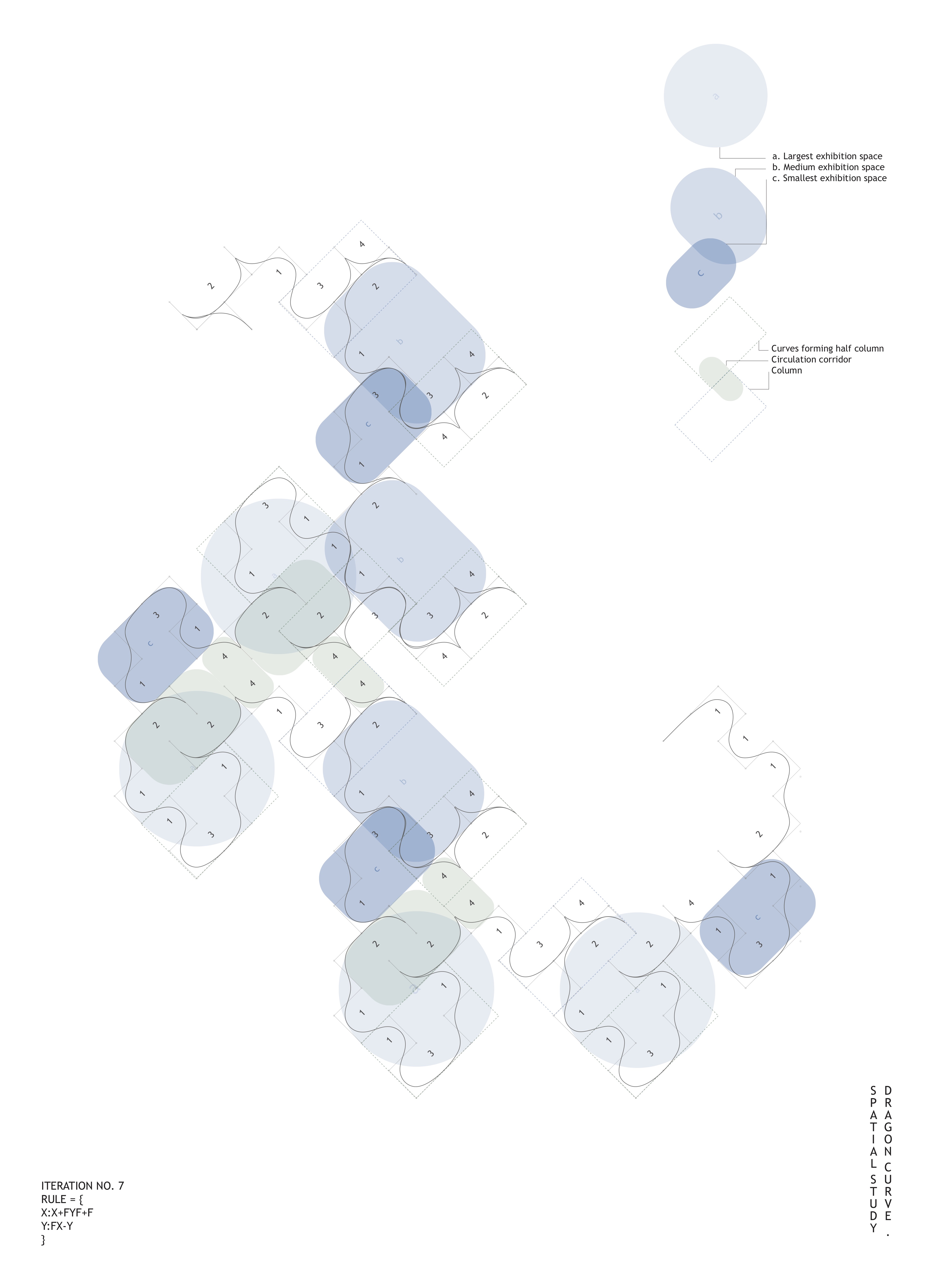
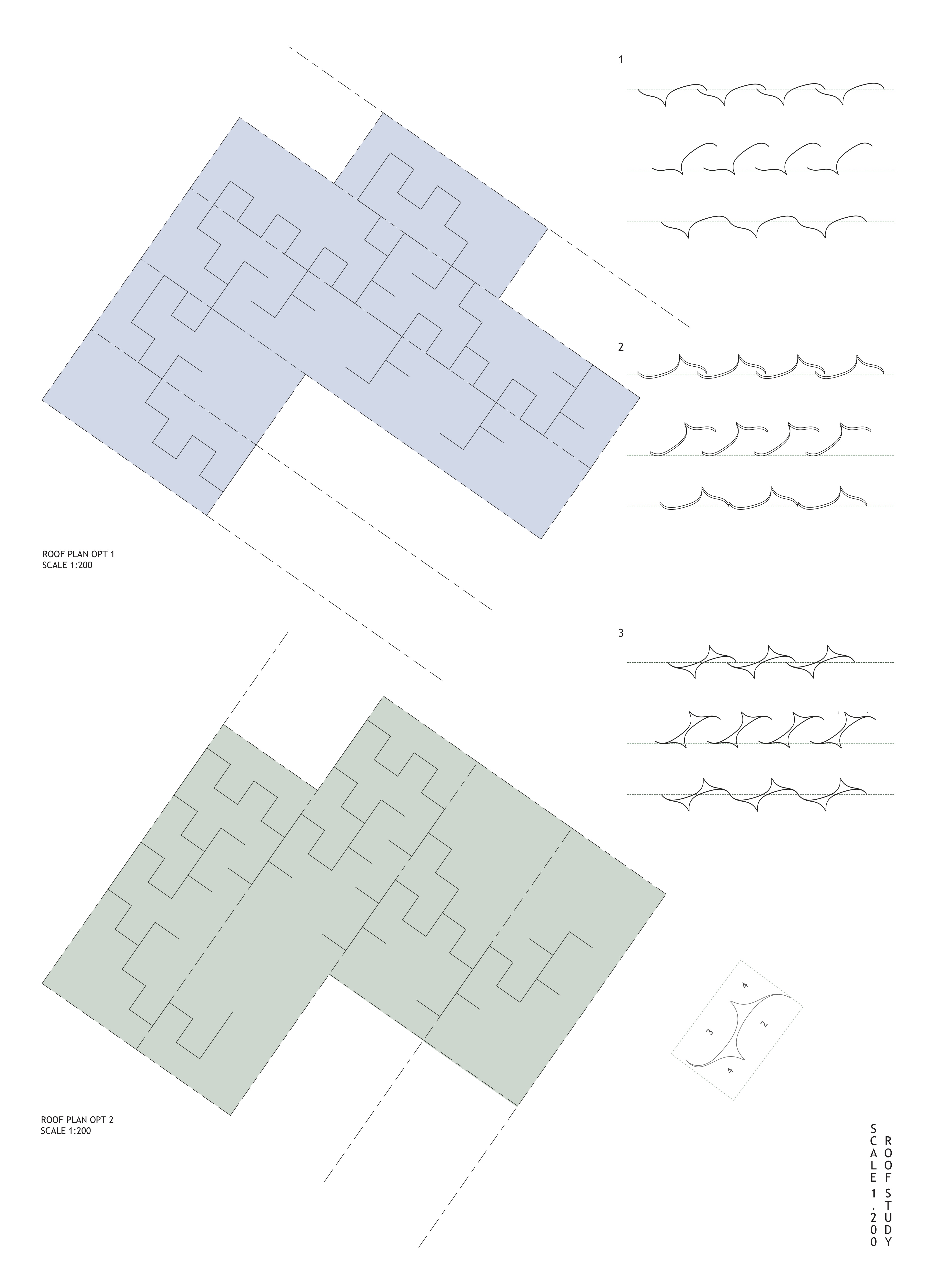
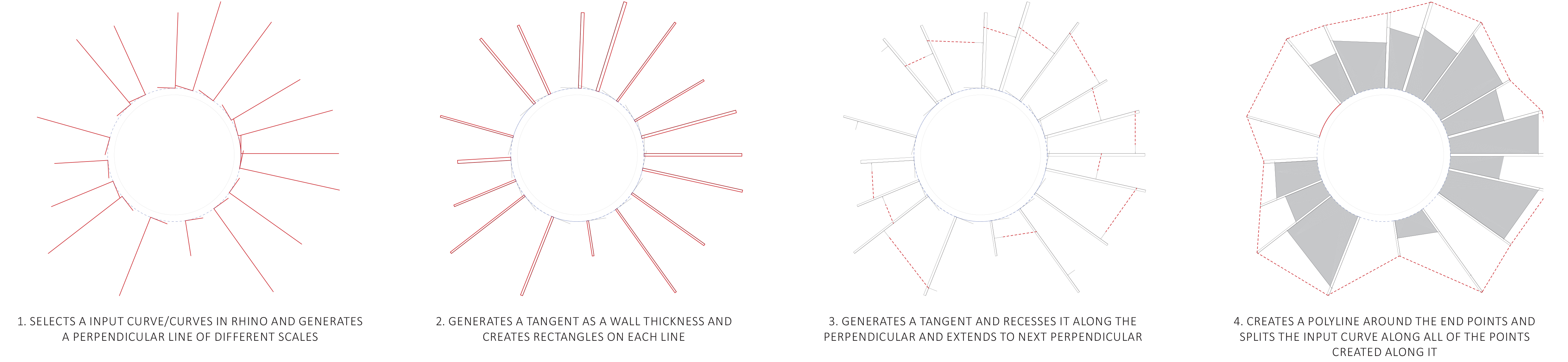
To begin the process of thickening the section within the project, I traced the path of the generated curve to identify four instances; 1, 2, 3, 4. Grouping the repetition of these instances, three distinct spatial conditions with aspect to the program were identified: exhibition – a, b, c; structure – column; circulation – corridor/ buffer spaces. Working in parallel with the roof structure, the control points and the path of the curvature is used as the defining grid for the roof. An instance of the curve geometry was used to generate the profile for the roof.
Each of the identified groups hold a combination of spatial characteristics such as flat, concave and convex surfaces. Without giving a set program to these, there is an opportunity to play with volume and the relationship to the ground and roof to provide a series of spaces with unique architectural qualities and views.
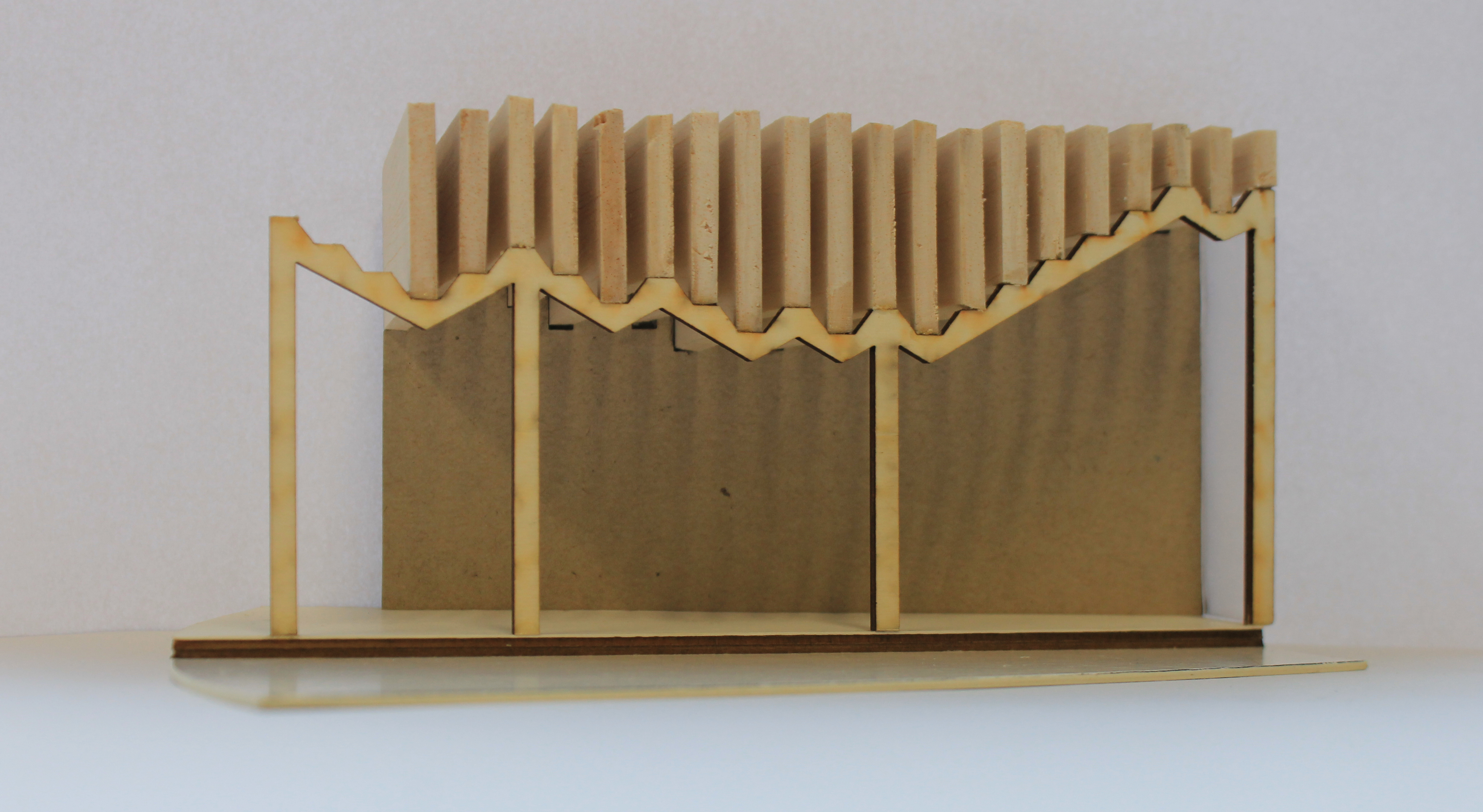
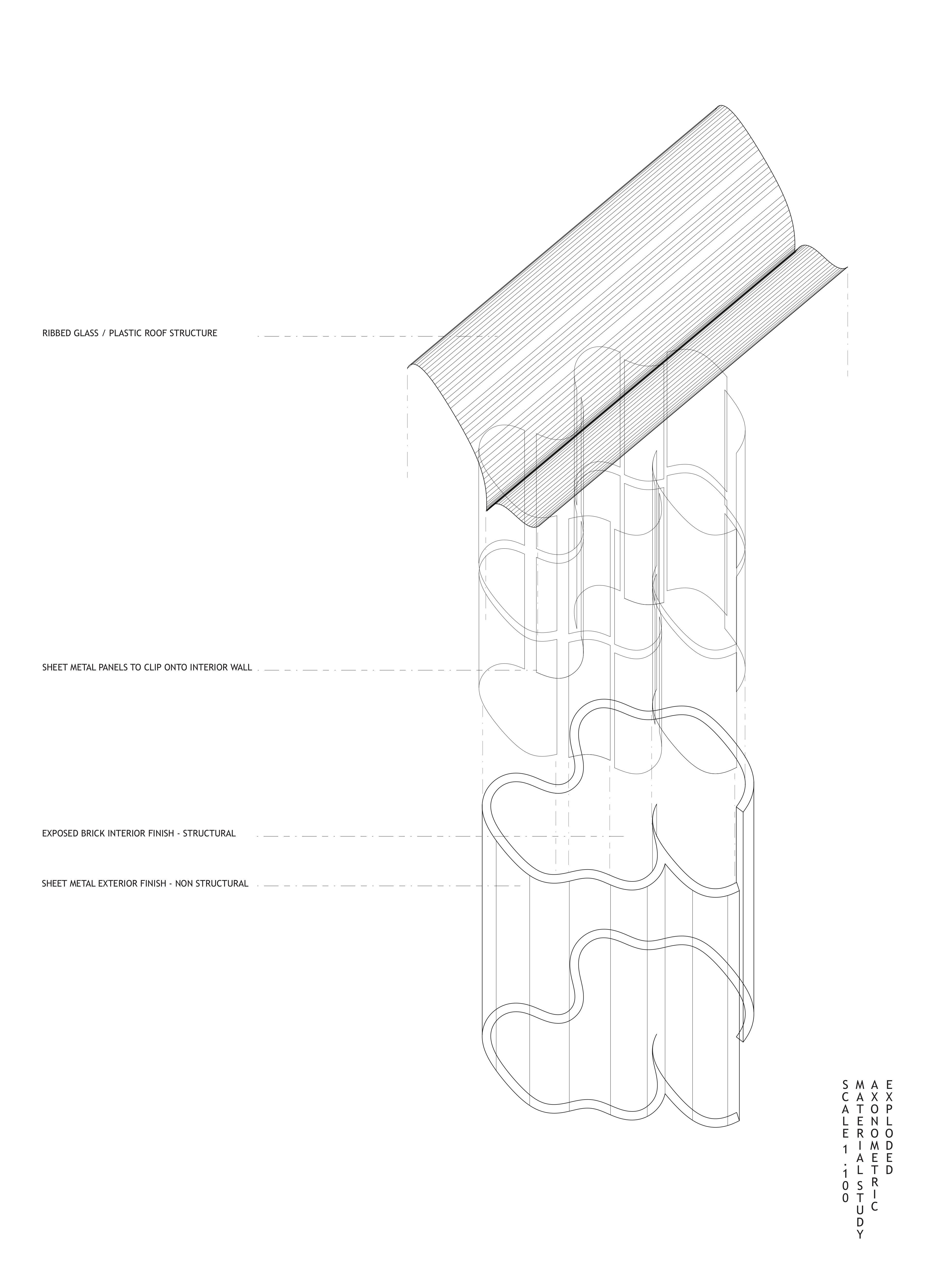
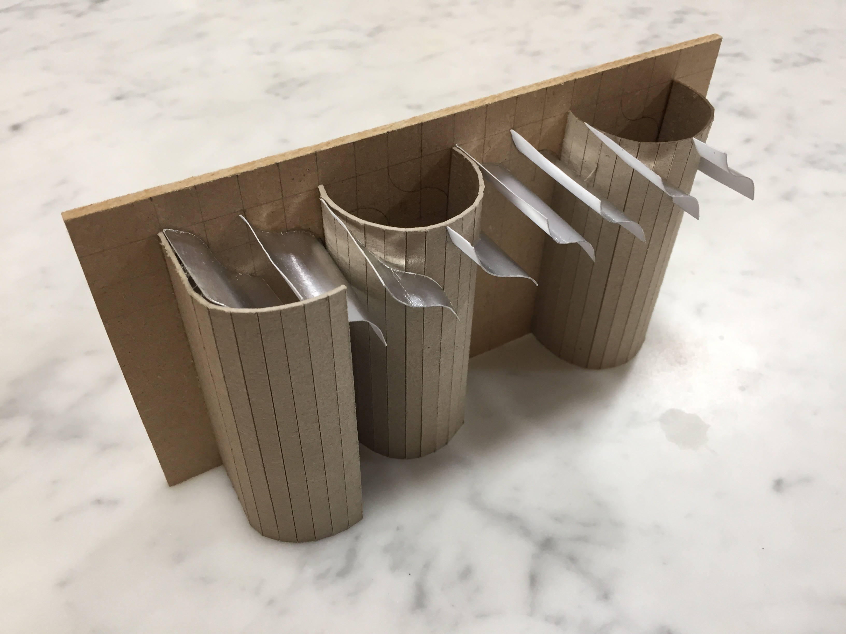
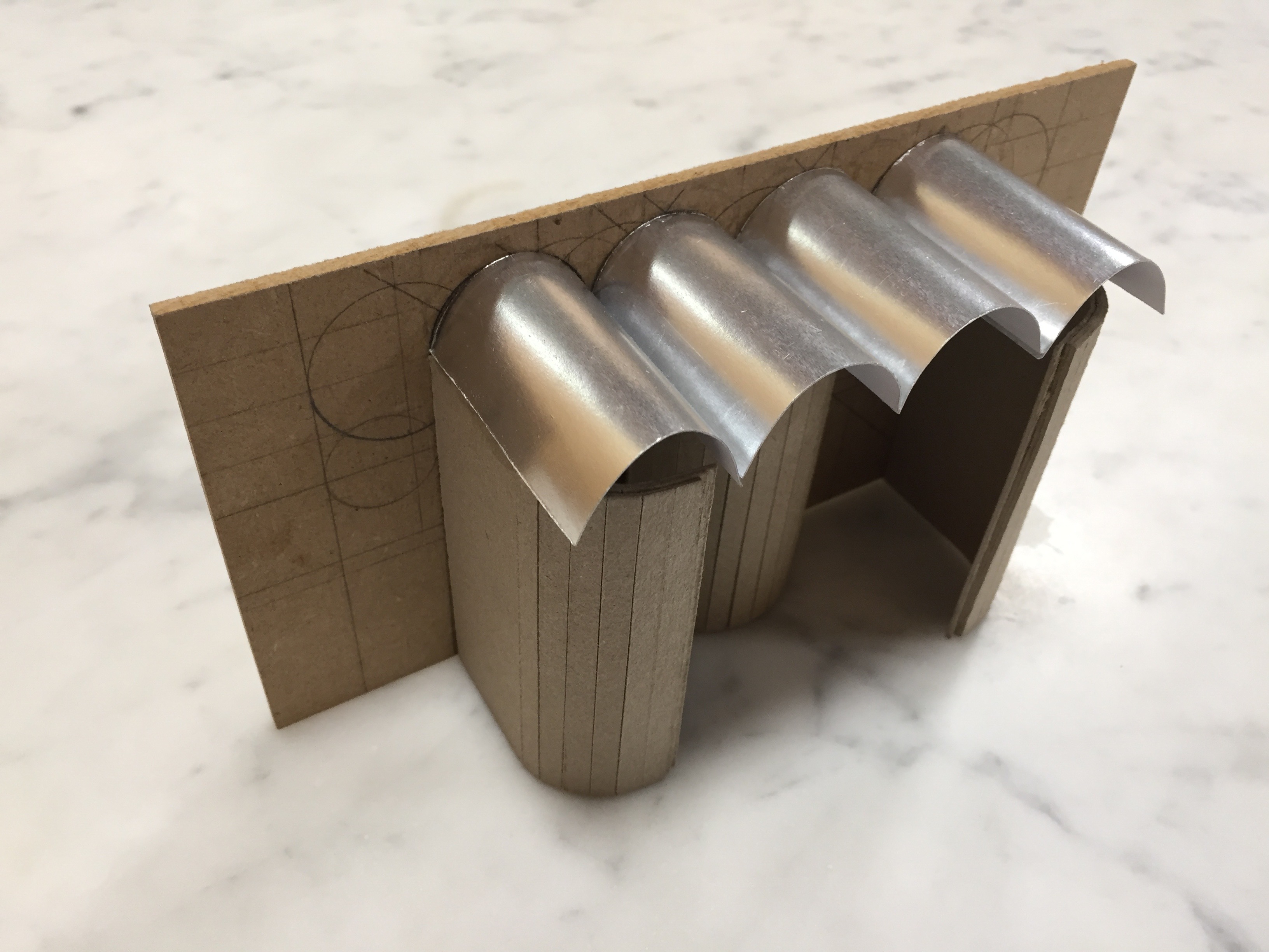
Adding thickness to the sections brings about the question of materiality. Keeping the idea of reflectivity and blending in the landscape, a sheet metal finish along the length of the exterior would enforce the sense of continuity. An exposed brick interior could be offset with sheet metal panels to provide different experiences of the space. The sectional model/ drawings, at a scale of 1:50 explore the spatial and tectonic characteristics of the roof and curve such as light, movement, thick and thin.
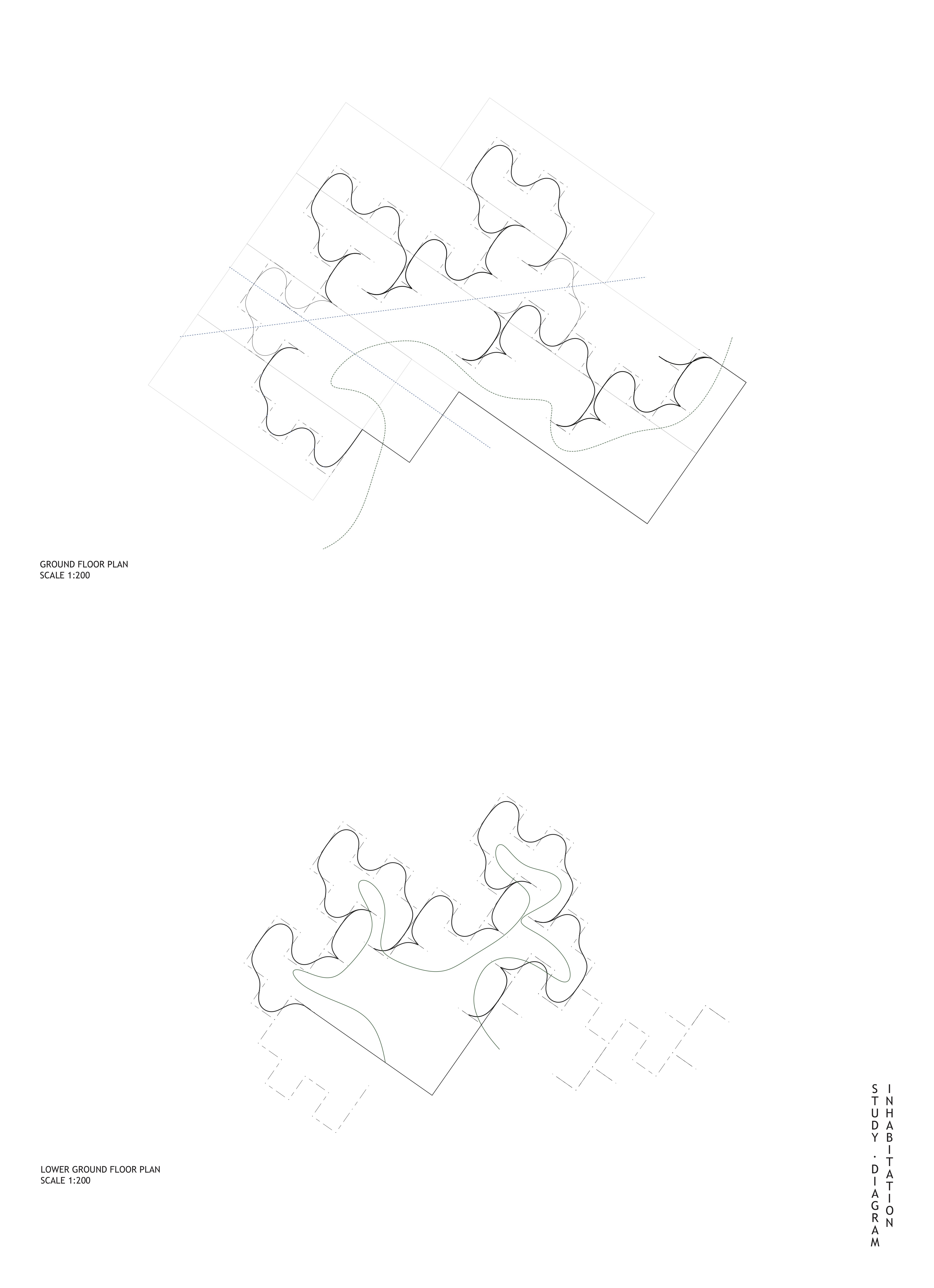
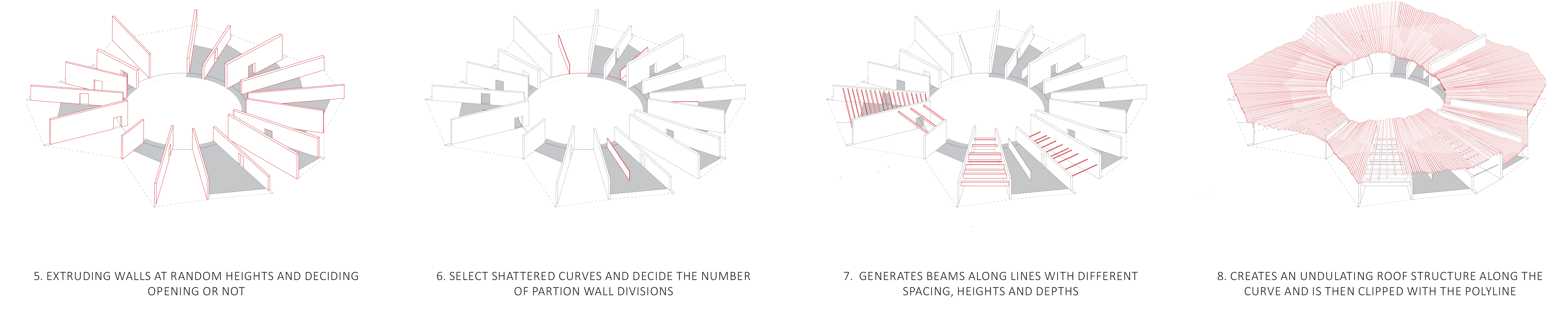
After producing the axonometric development drawing , I used this as a snapshot to analyse how the code was generating spaces and controlling circulation. But most importantly to reflect on how the walls, beams and roof were working together through manipulation of the code. I started to alter the logic of the code to create a controlled circulation route through the spaces. By randomly deciding whether to shift a wall and creating an opening, or leave the wall untouched.
I then also explored how different input curves could create different spaces and variations by using the same script.
Below is an example of one of the many unique generations that can be produced on the exact same curve. If used on different input curves I could create even more unique variations.
I started to look at the roof form in more detail by considering how it could vary in different ways to affect the environment and experience of the space below. I would then use this to dictate what spaces could be used for. I considered how the spacing and arrangements could be altered to let through different amounts of light, or no light if you want to project video installations. They could even be used as acoustic buffers in tall spaces. Whilst I was exploring the variations of roof form and the transparency of the walls to shut off and expose views, I still wanted the roof form to appear as one cohesive system.