
Studio 9: Architectural Notations
KTH Royal Institute of Technology Architecture School
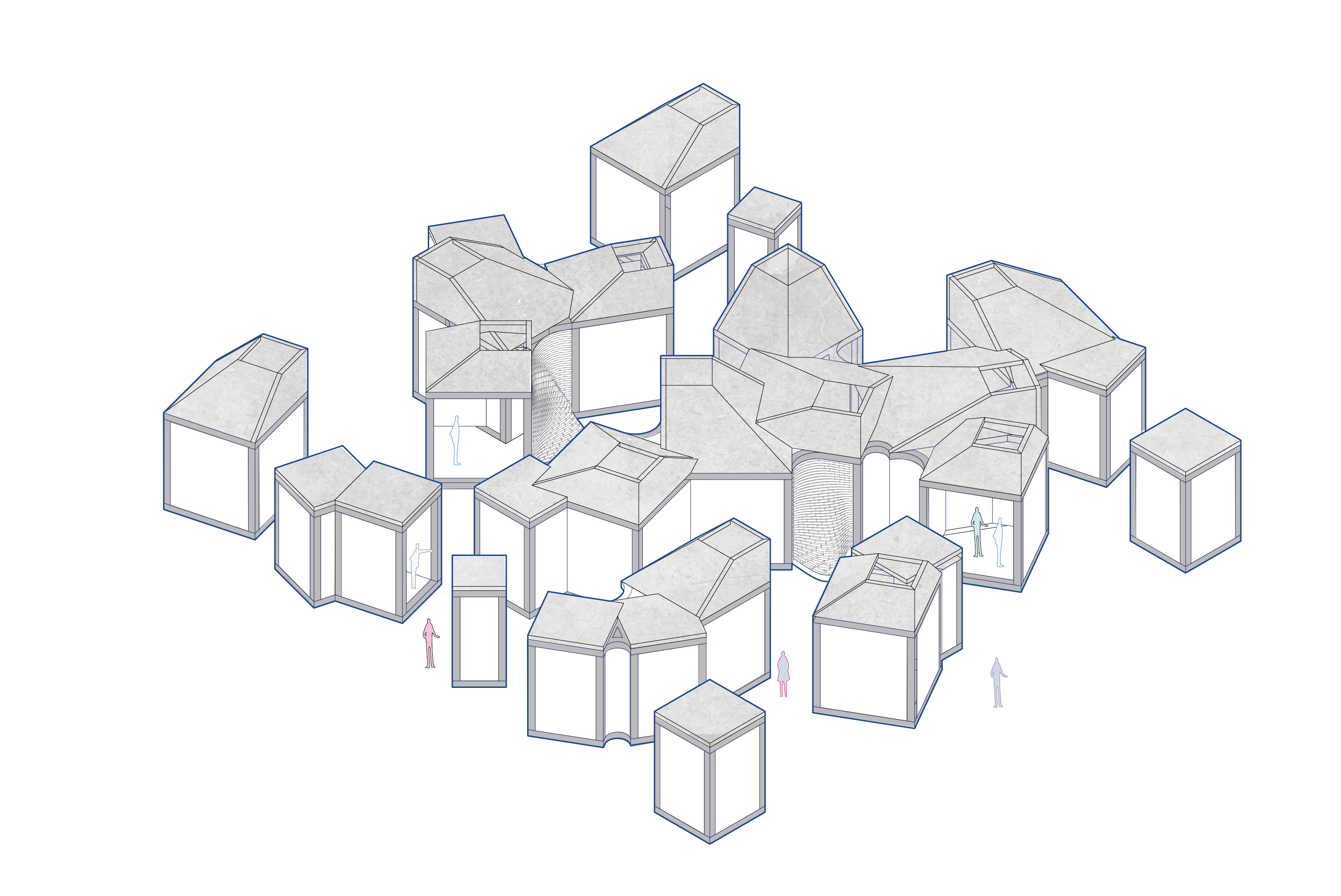
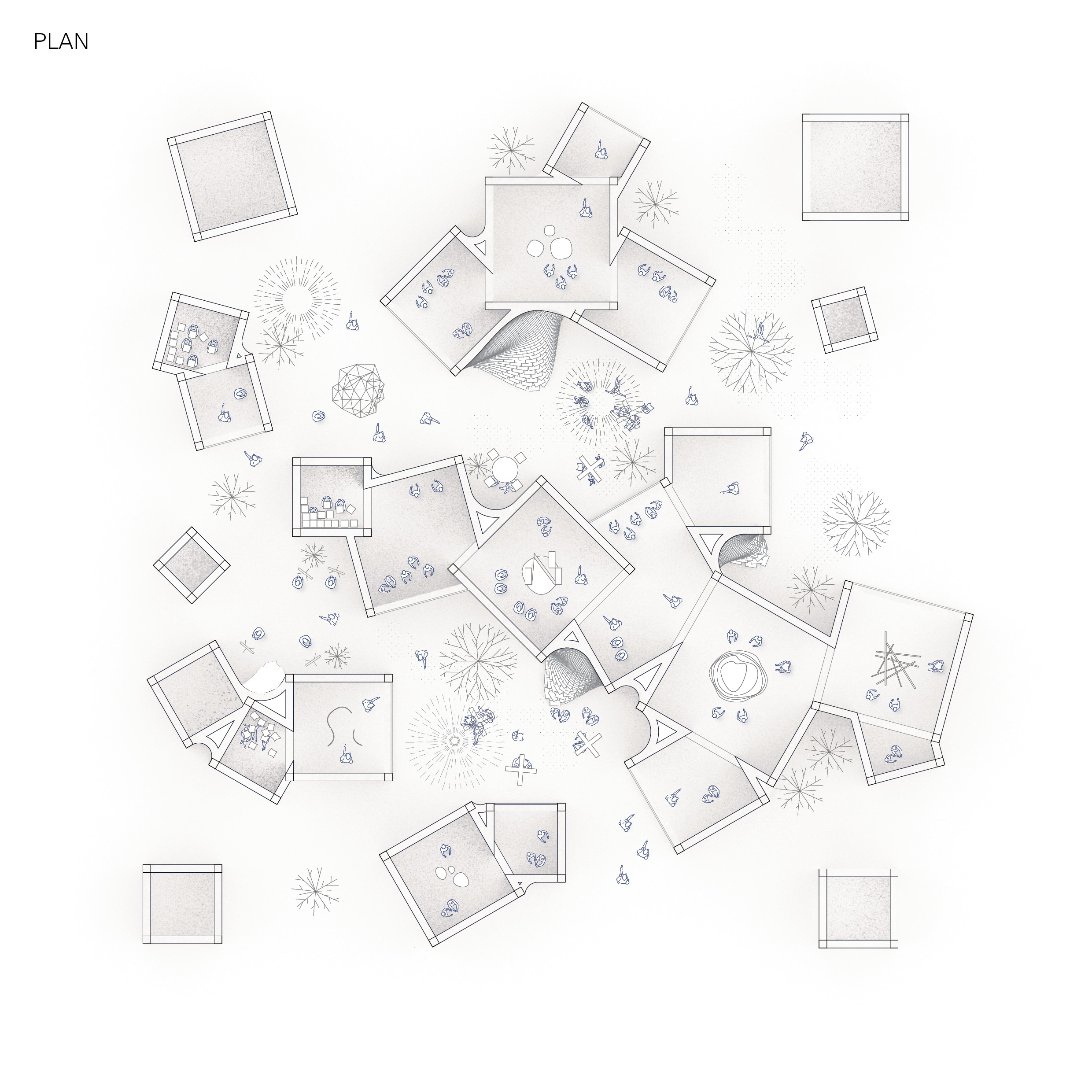
Since the last task, I had a look at re-ordering the code so that the circles are extruded first, and then performing a boolean on the cylinders. This has the benefit of more variety in the heights of the rooms, and more interesting 3D intersections.
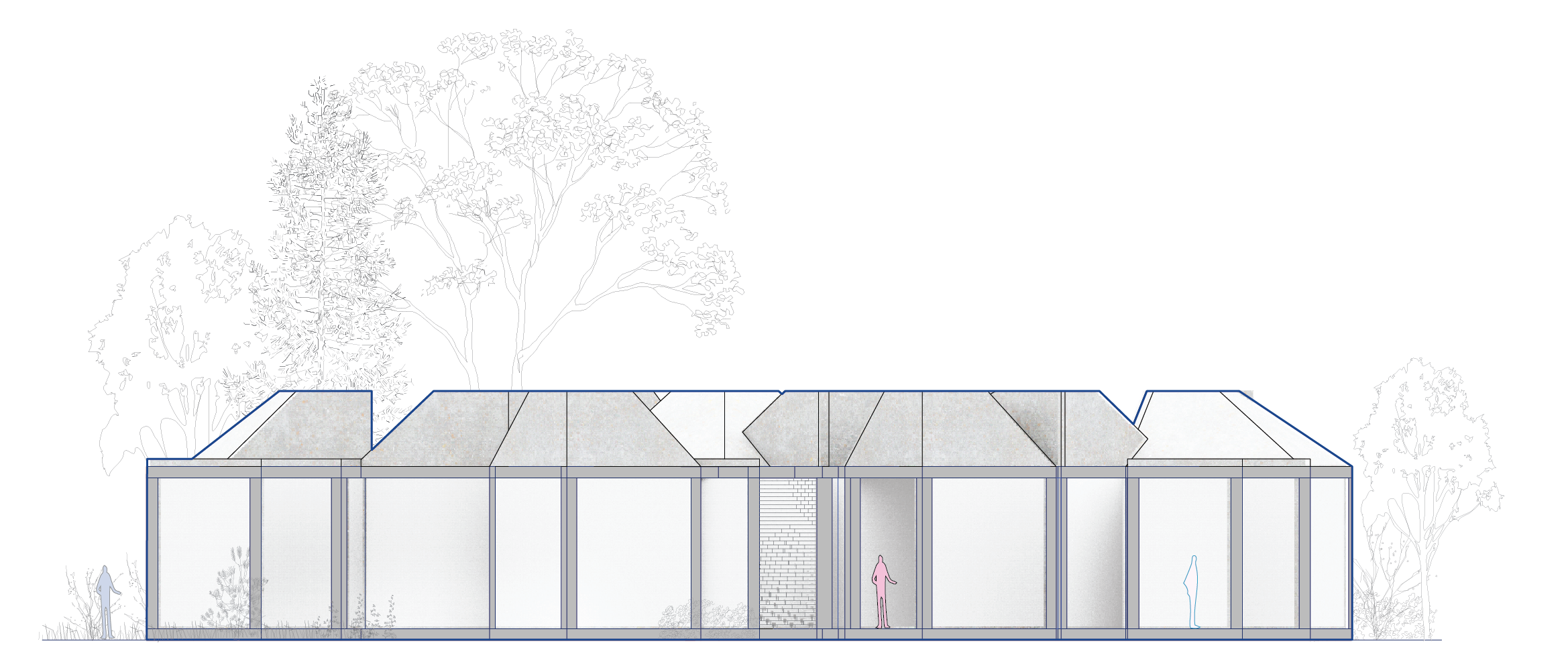
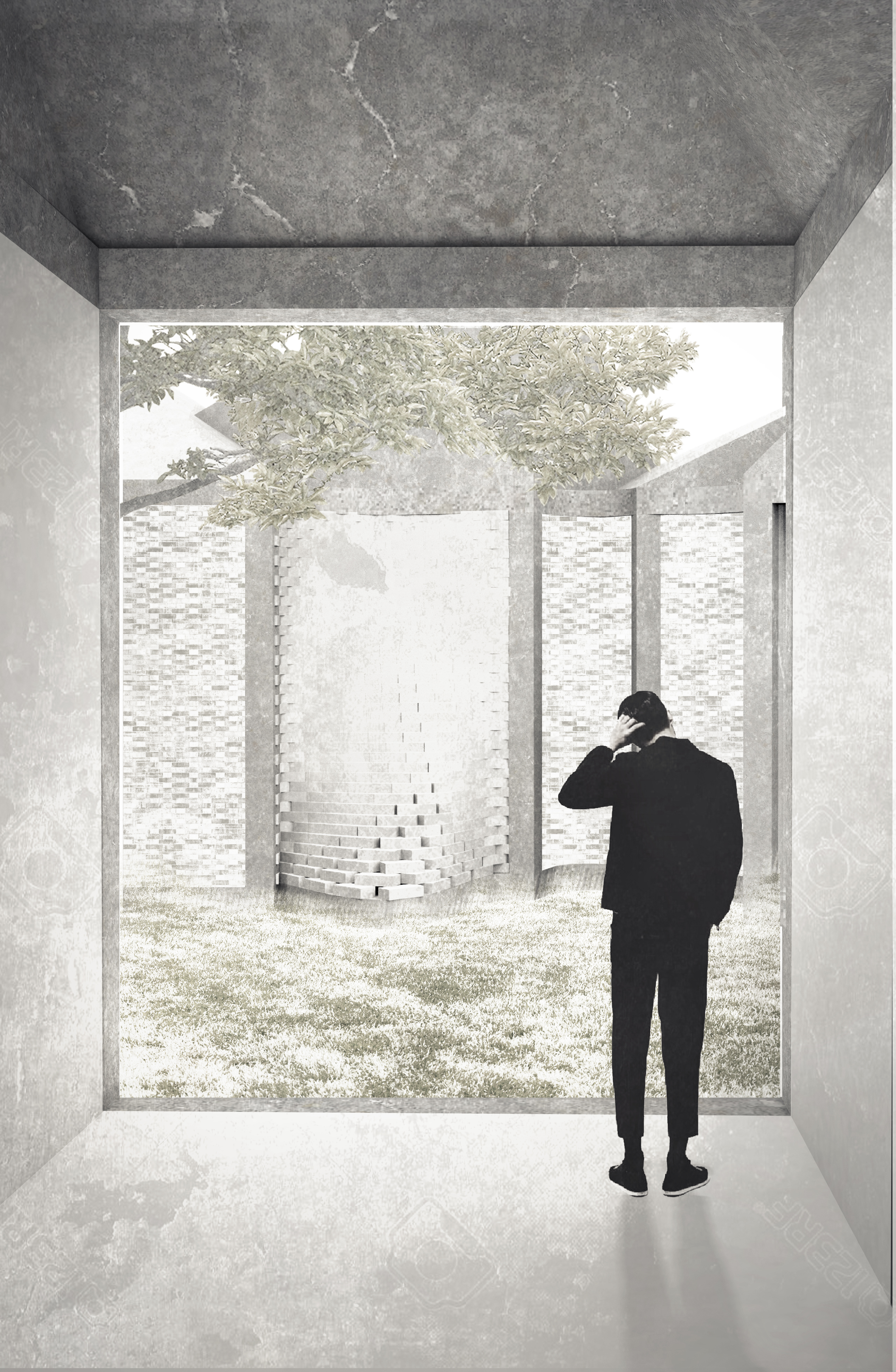
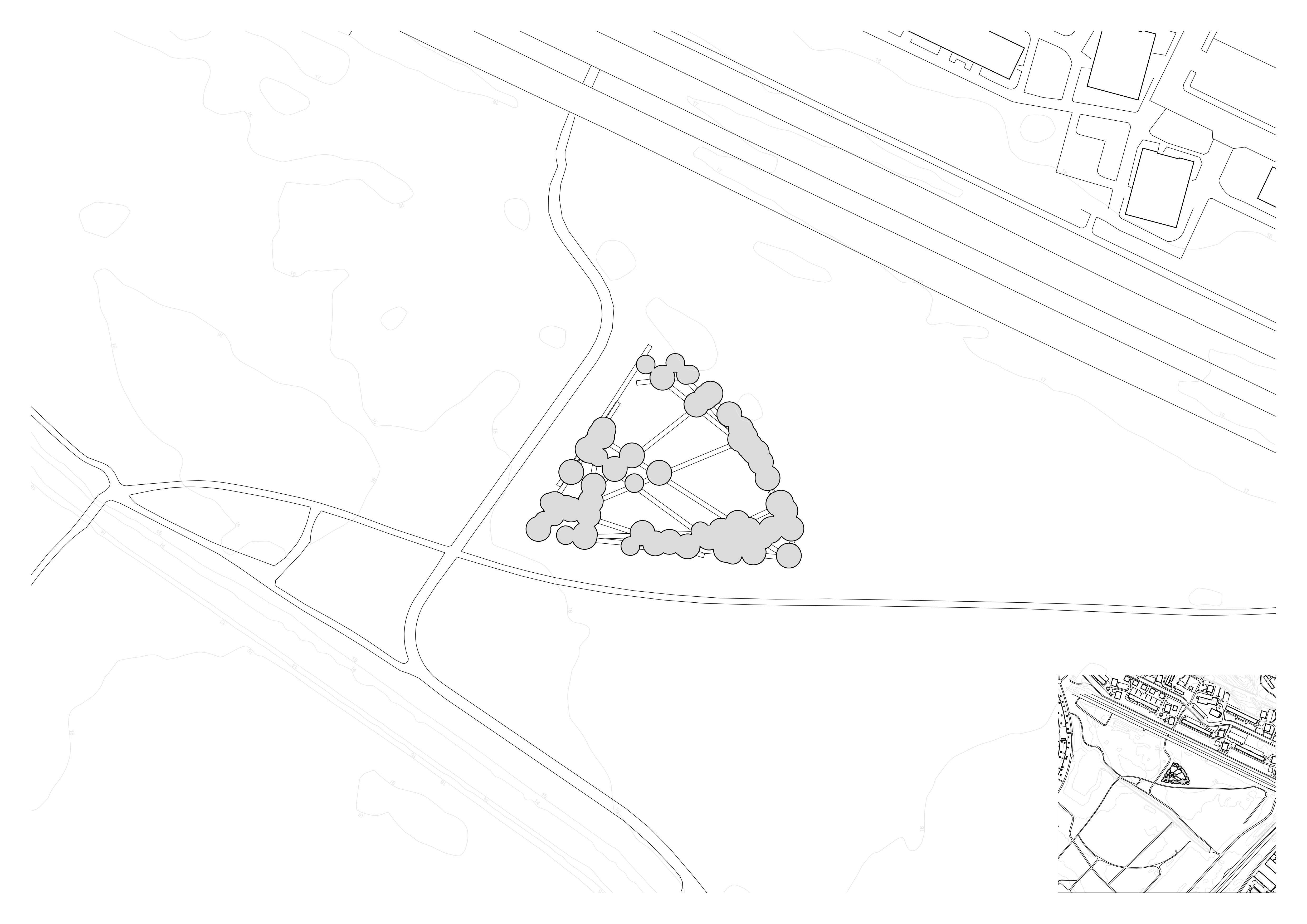
Looking back at the site, I chose a boundary that had multiple paths leading into it, with the idea that when wandering along the site one can wander in and out of the konsthall. The generated paths are a combination of internal corridors and external paths, providing a sheltered route as well as the option to move outdoors between the clusters, like paths through the park.
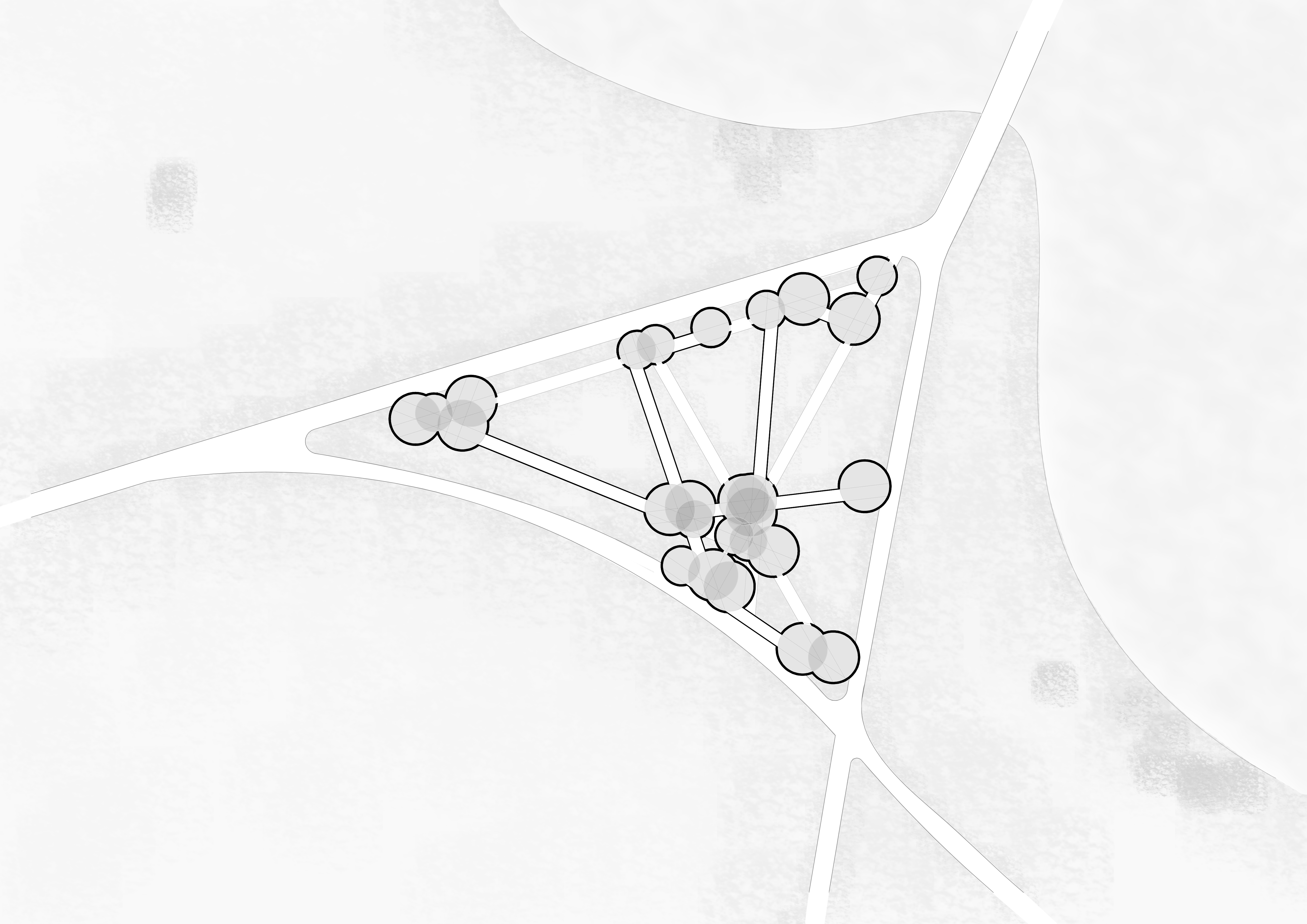
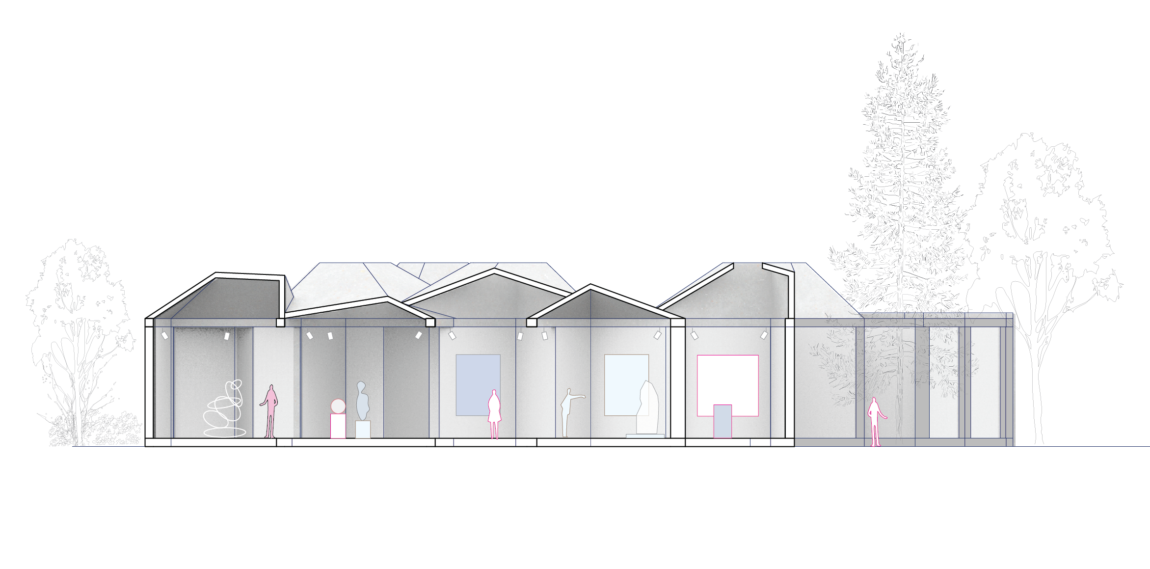
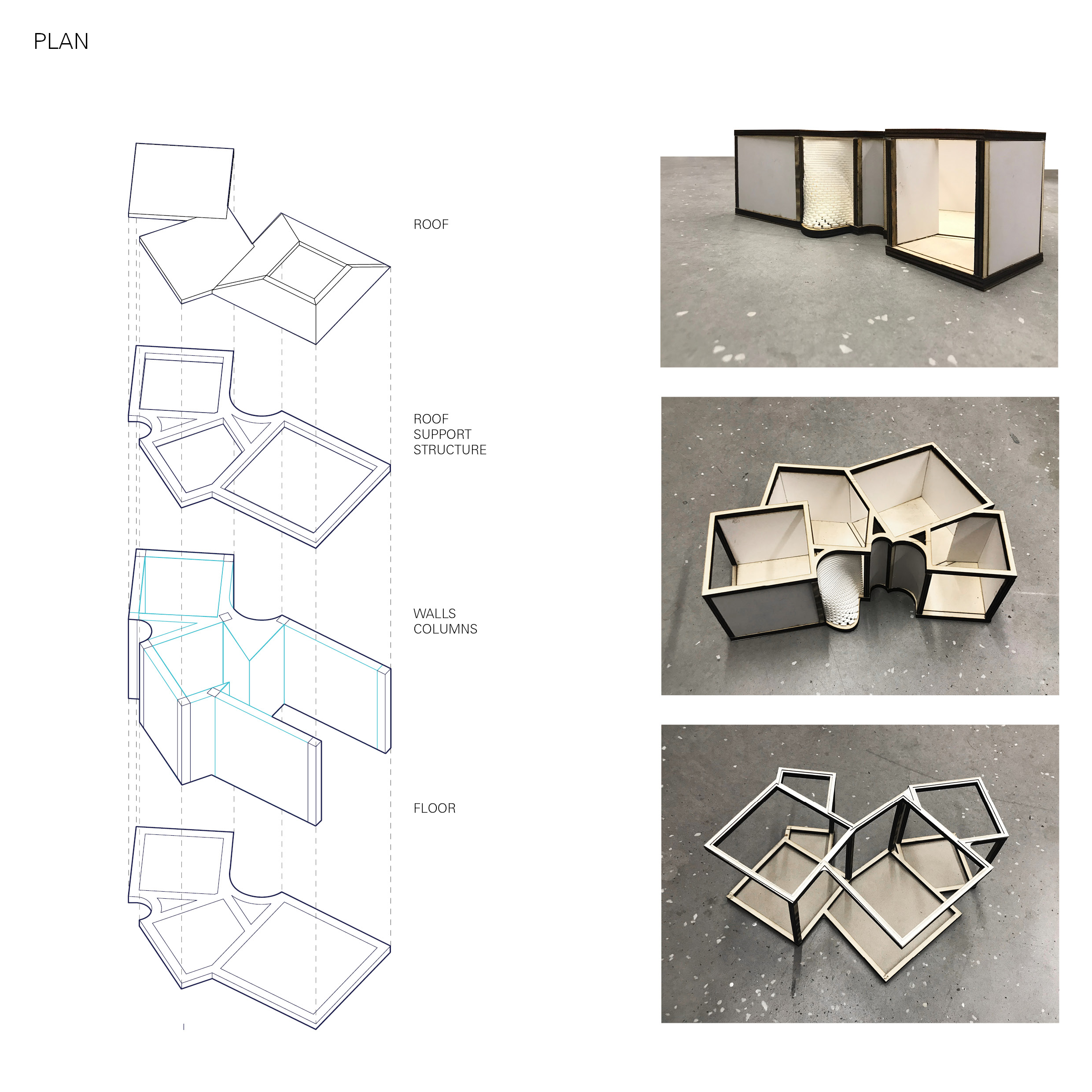
The circles, which are still clearly visible in plan, provide an opportunity to further express the direction of the paths that generate them. By adding a linear structure to the roof, following the direction of one of the paths, a simple but interesting ceiling is created. Where the circles overlap, it creates a more intricate lattice.
The alignment of the roof structure makes the paths even more legible, and the roof provides an opportunity to bring natural light into the spaces.

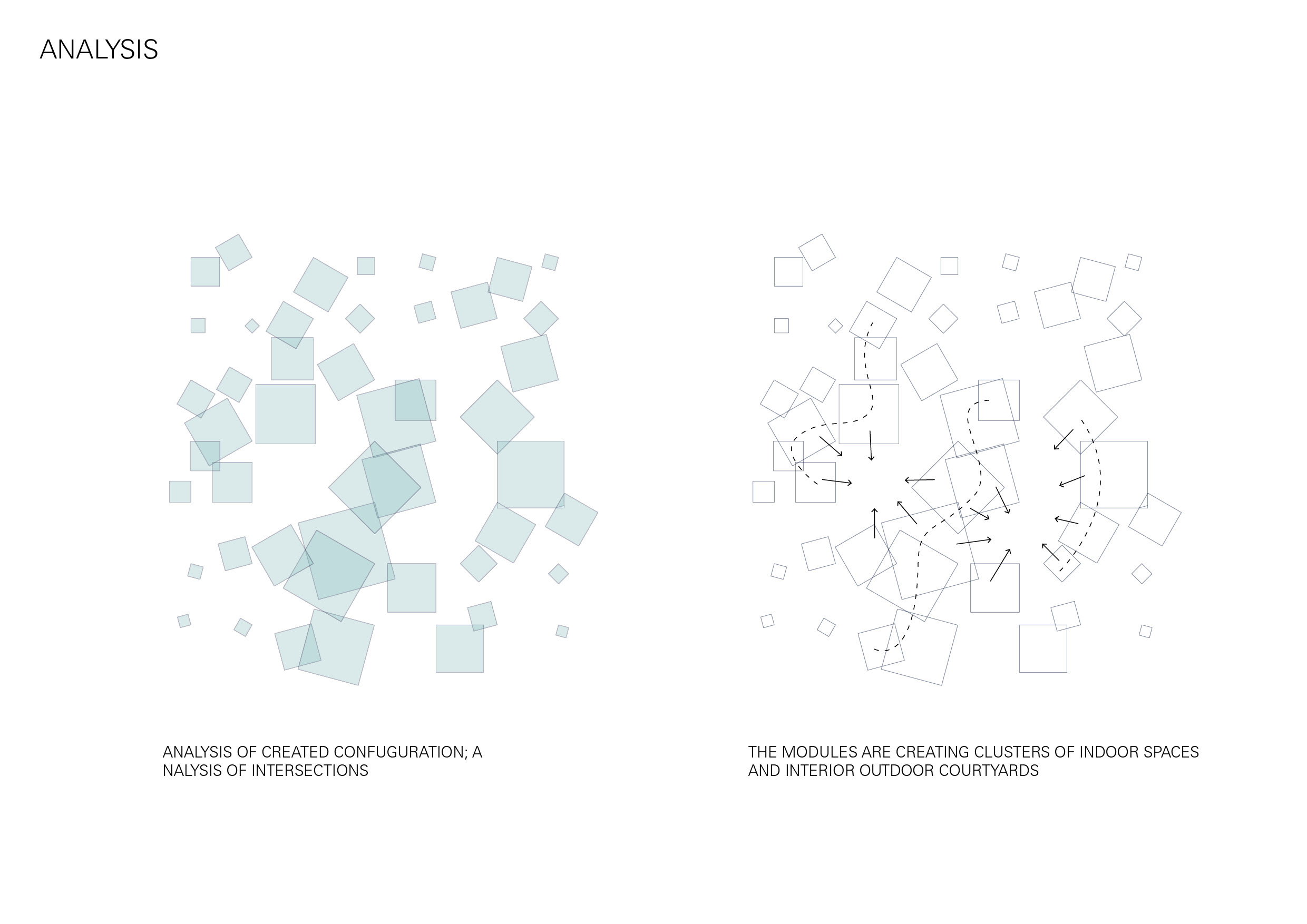
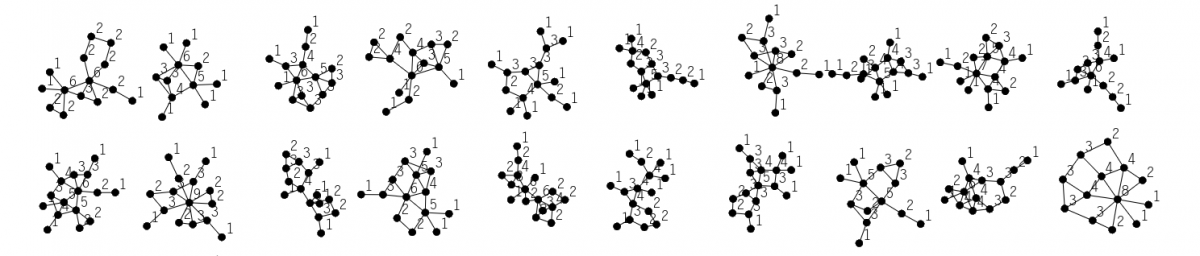
Looking at spatial configurations of existing plans, I found layouts interesting that had more unconventional circulation patterns. In particular the spaces that were formed through the resulting overlaps or intersections.
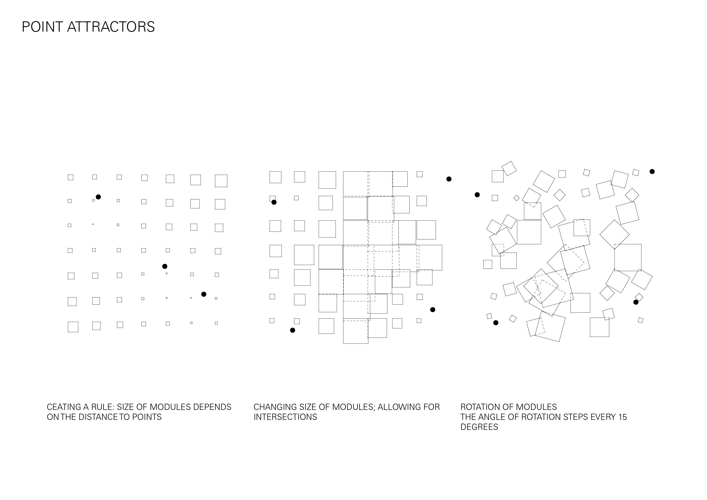
I began by looking at the spaces created when horizontal and vertical walls were randomly arranged in a uniform grid. Developing this further I introduced a wider variety of rotations and intersections to see how this would impact the spaces in-between.
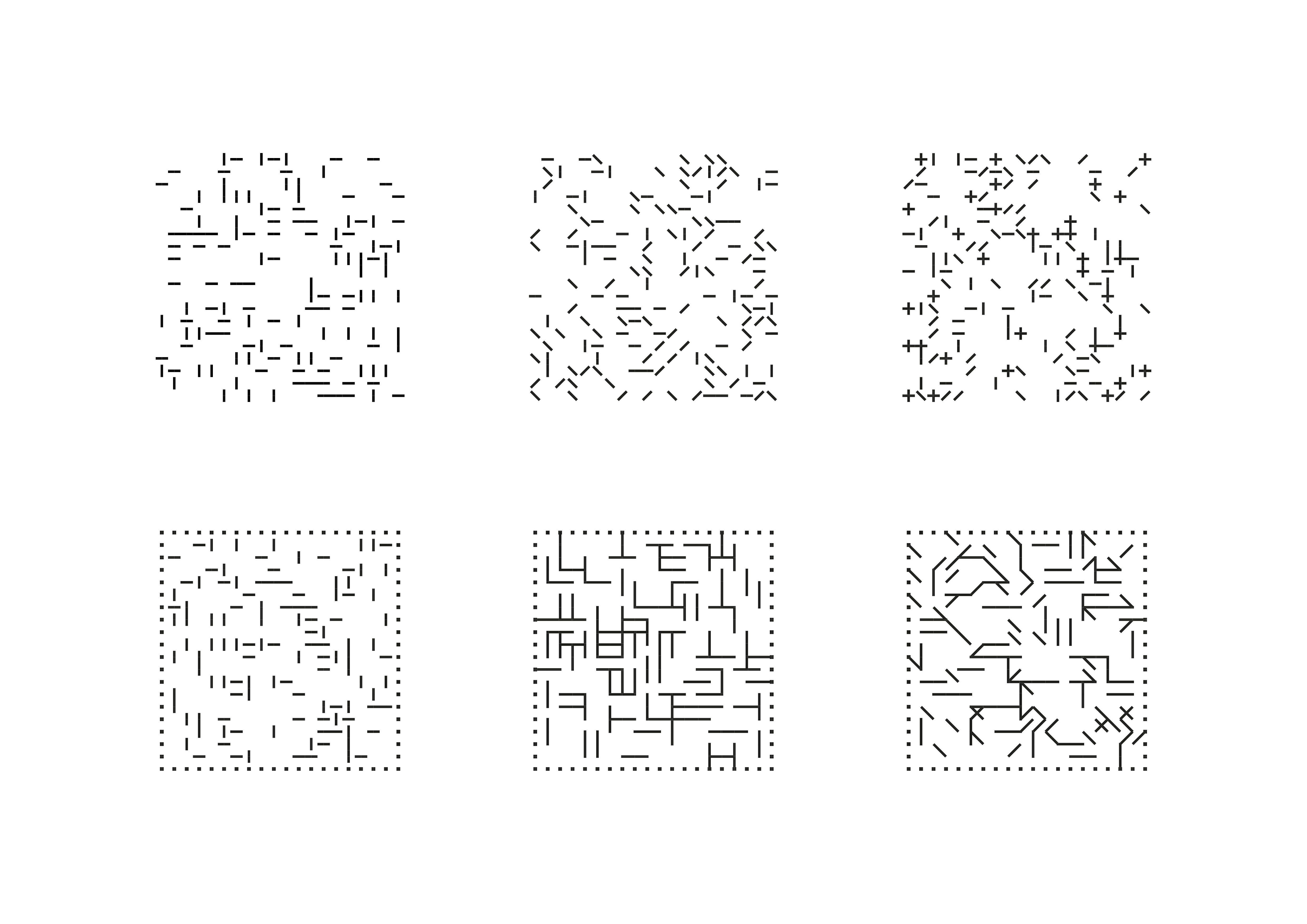
In an attempt to escape the rectangular boundary I experimented with sequences of squares and circles in different sized grids, creating spaces from the overlapping boundaries. By merging these varying scaled shapes as if they were layered, I was able to begin to create a more hierarchical spatial pattern.
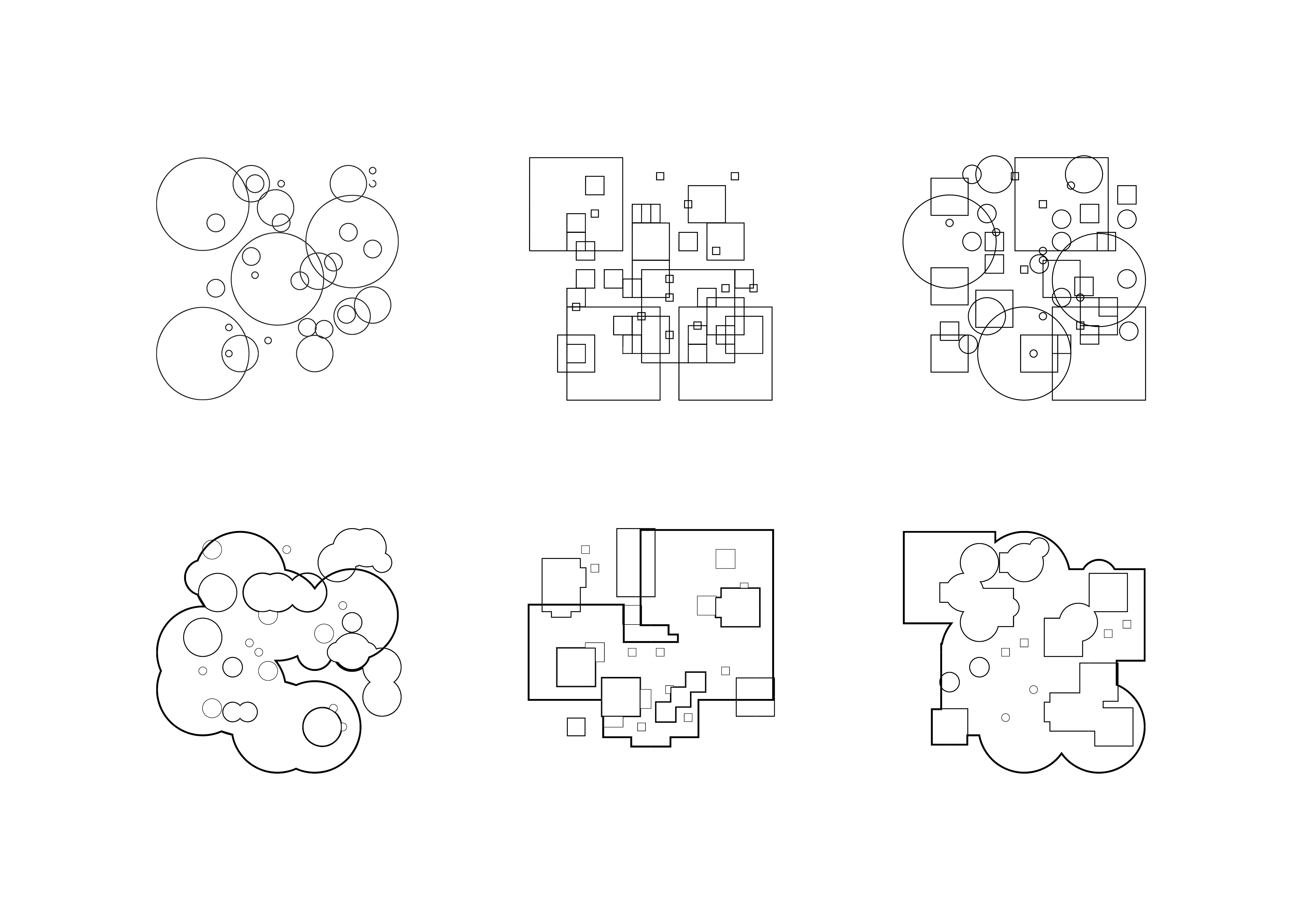
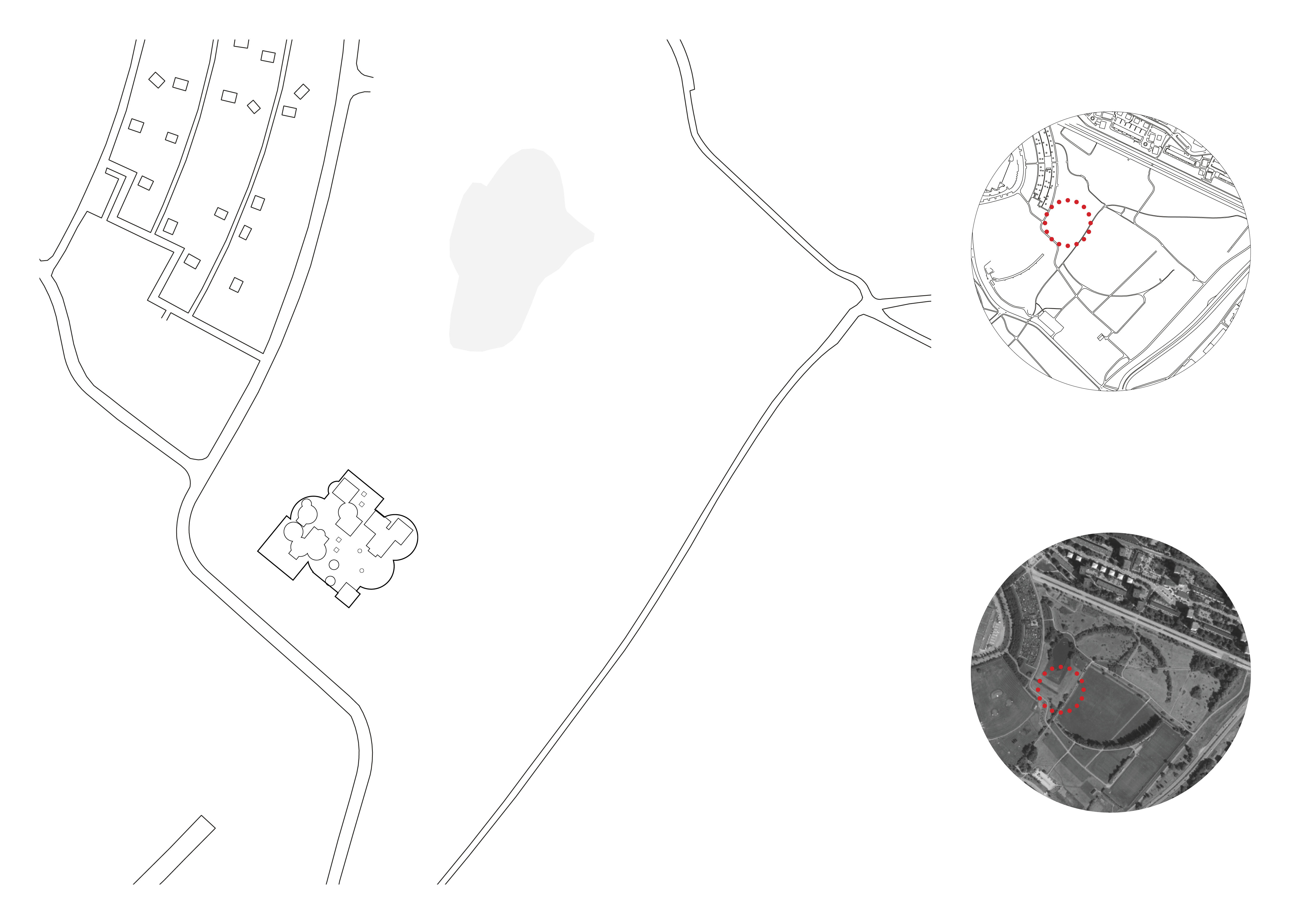
Additionally, I began looking at how one of these patterns could be placed on a site, and will explore further how aspects of the site could be implemented as parameters for my future code.
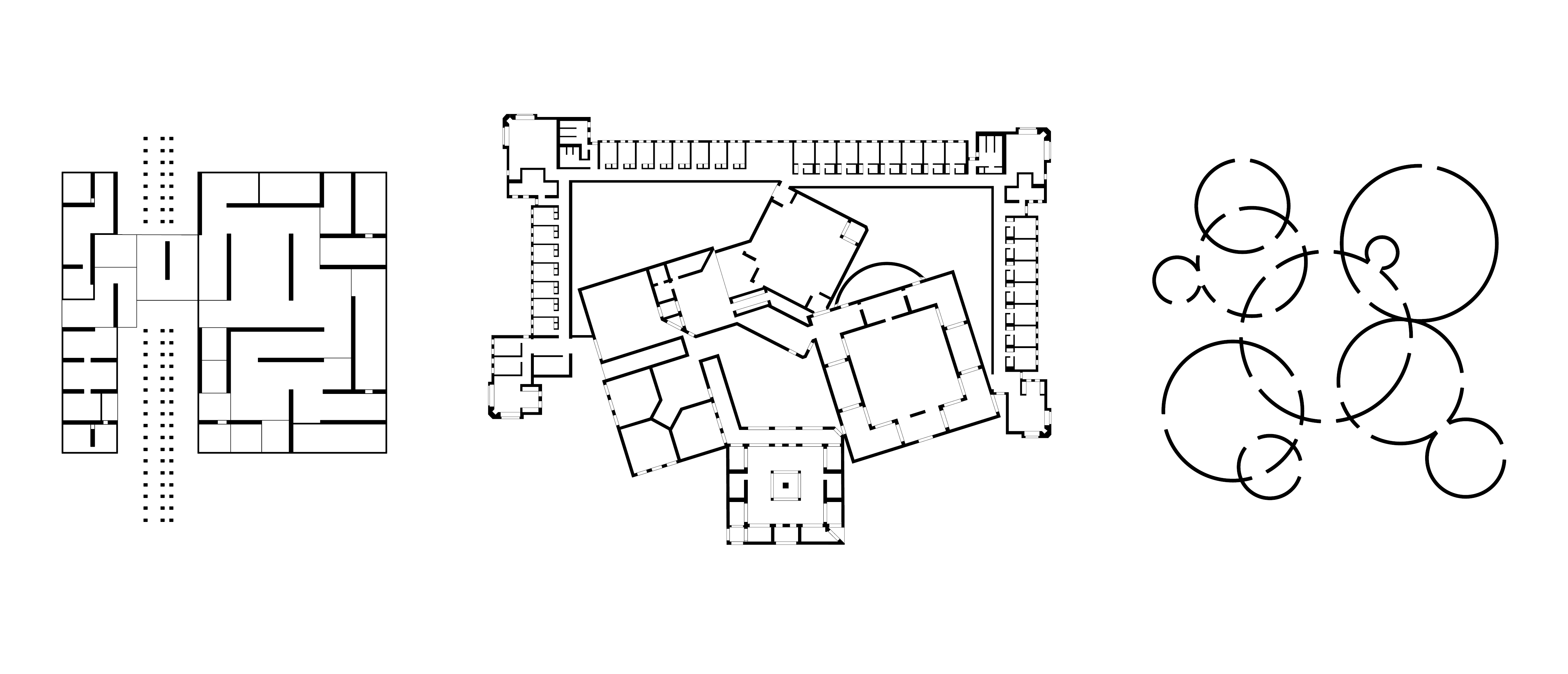
I was inspired by the ”calculated randomness” of plans like Fujimoto’s Children’s Center for Psychiatric Rehabilitation, where the programmed elements seems to be randomly shuffled.
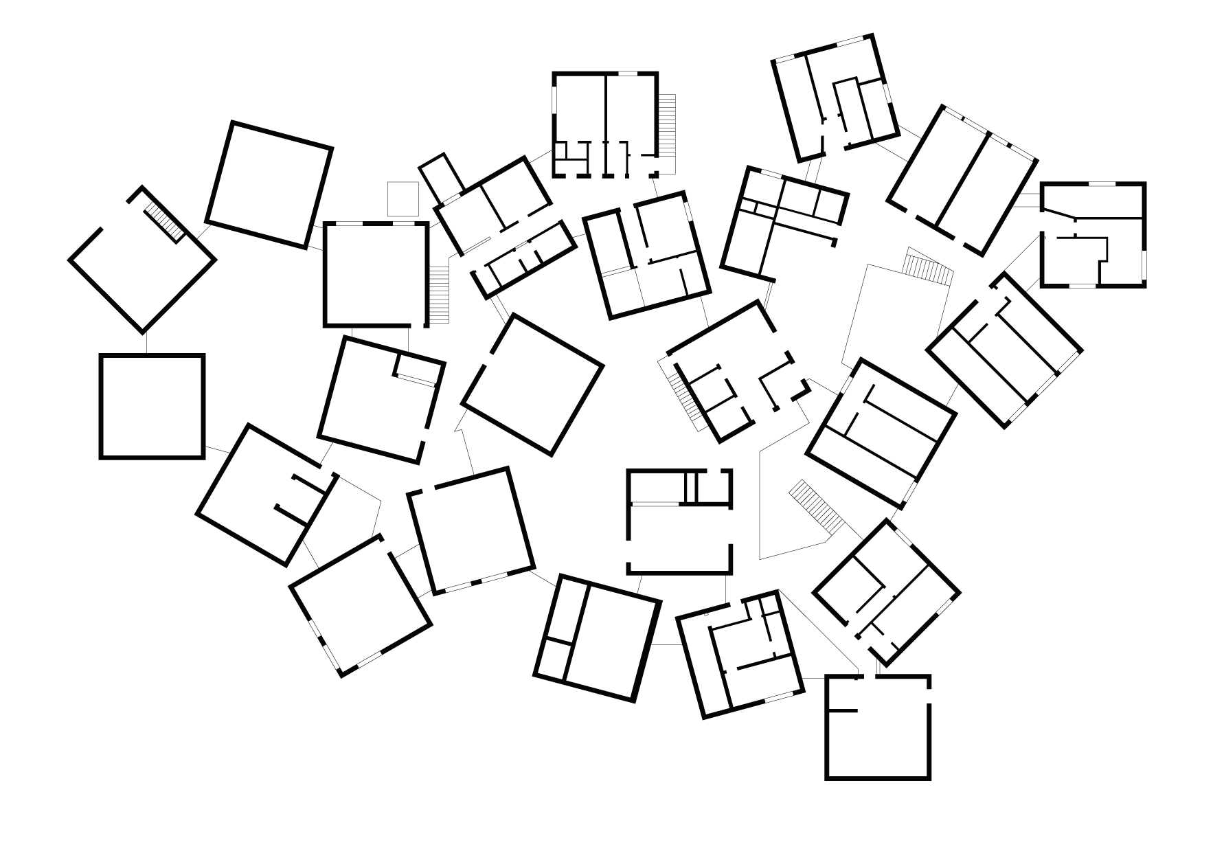
With set parameters – conditions for form, construction, utility, site and so on – in combination with automatic randomizing many different propositions of such plans could be generated through programming, and maybe result in finding unexpected configurations.
I created a program that could shuffle objects like walls, rooms, pillars by placing them randomly on a predetermined area and assign each a randomized angle (A_001). This generated plans that was totally random, and though I could change the values of angle and plane, the arrangement of the elements was uncontrollable.
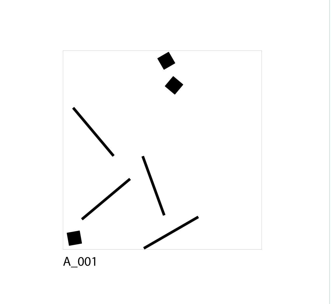
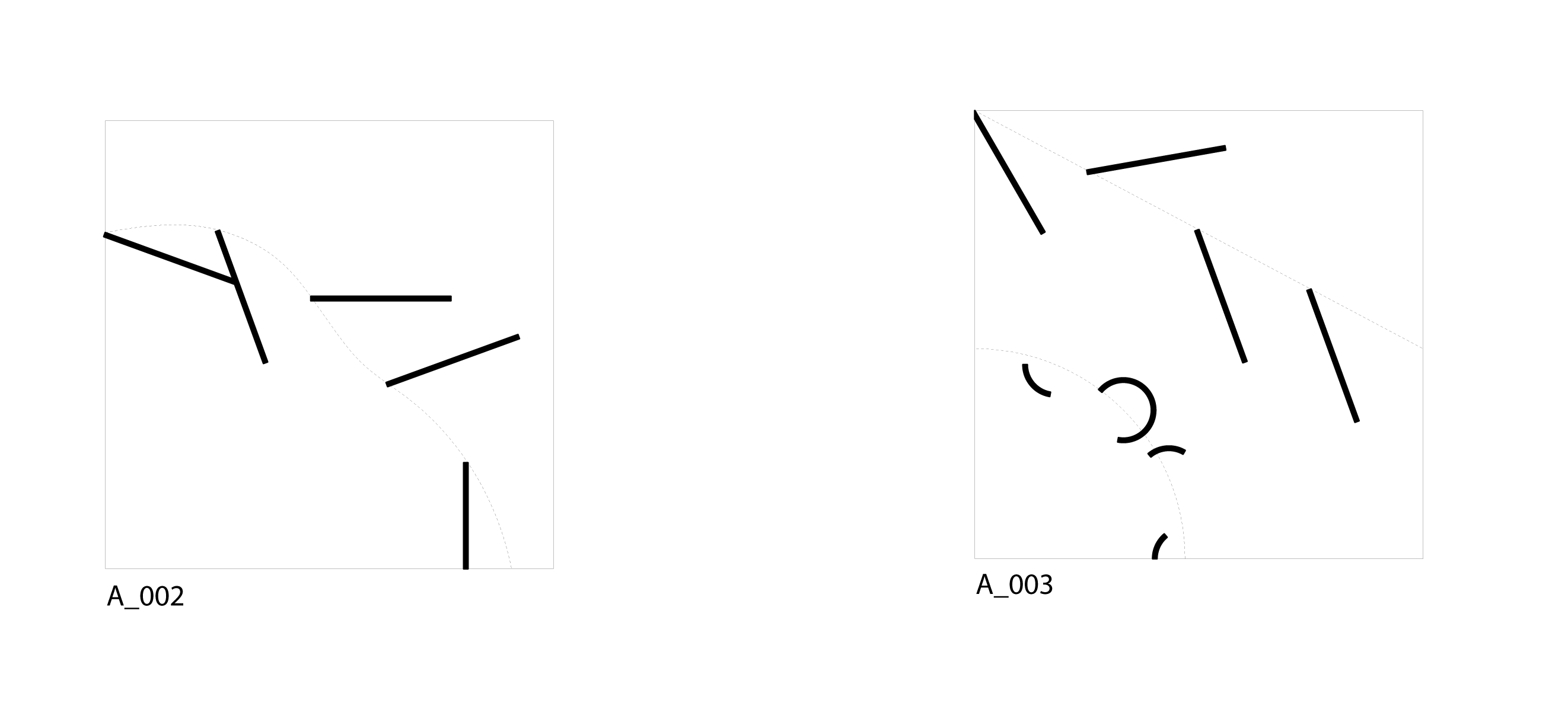
From that I tried to add controlling parameters by using predetermined objects like curves to add a level of intention, though still keeping the randomness of angles (A_002 – A_003).
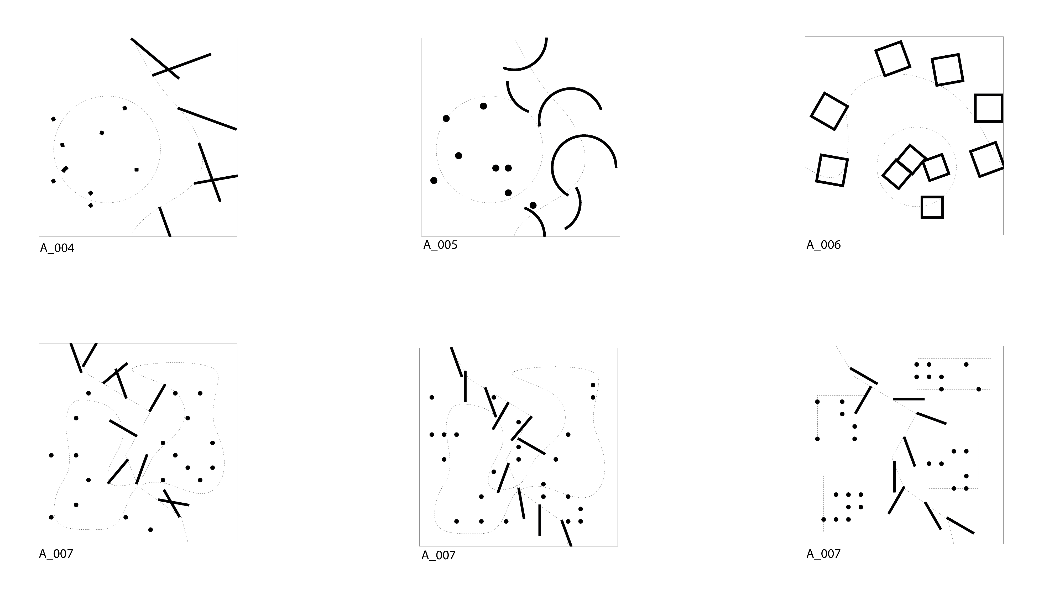
By constraining the random shuffling within smaller areas the outcome could be further controlled. By using a combination of these two methods (within area and along curve), and experimenting with different types of elements, I could generate outcomes that were generally controlled and still quite unpredictable each time (A_004 – A_007).
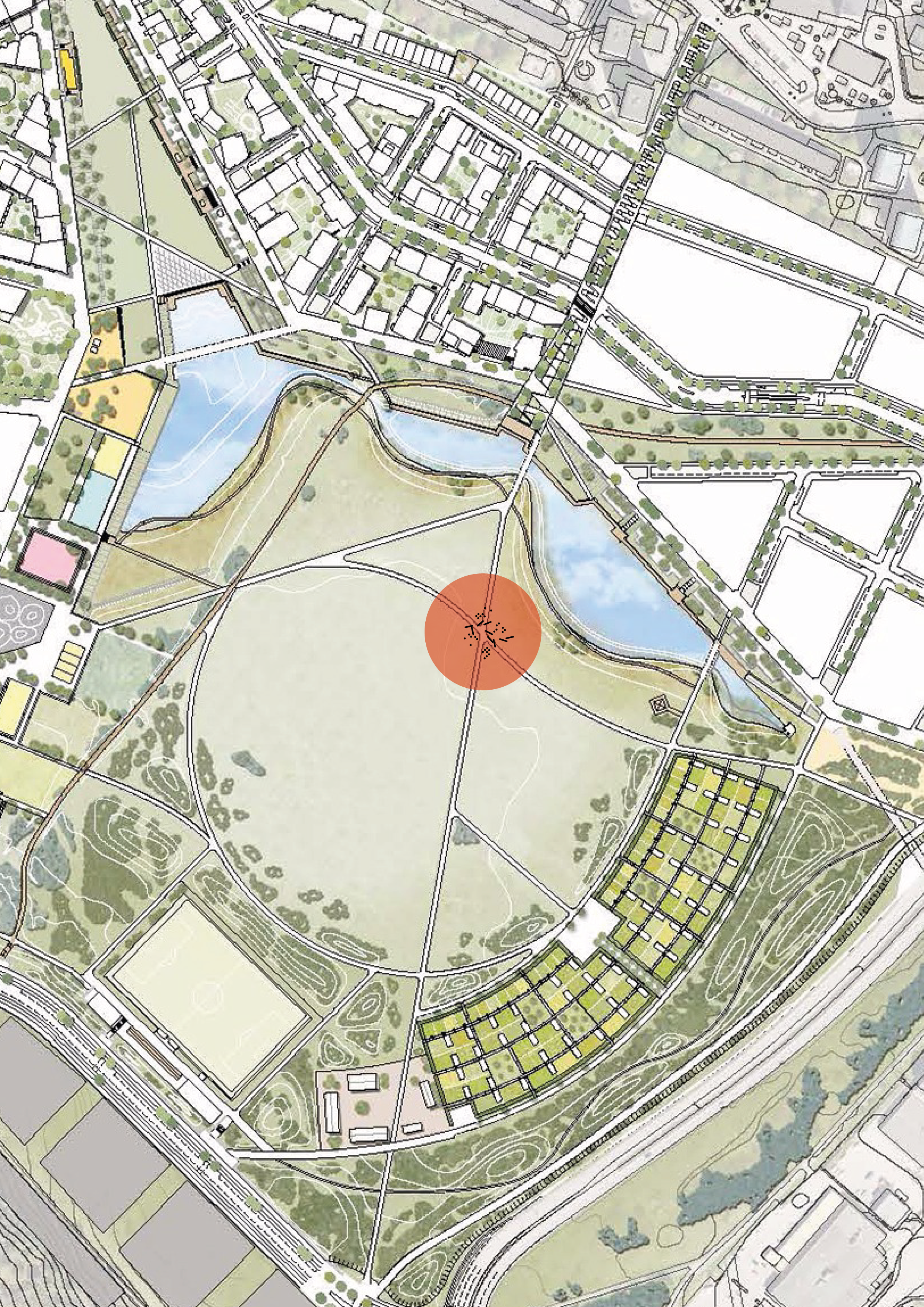
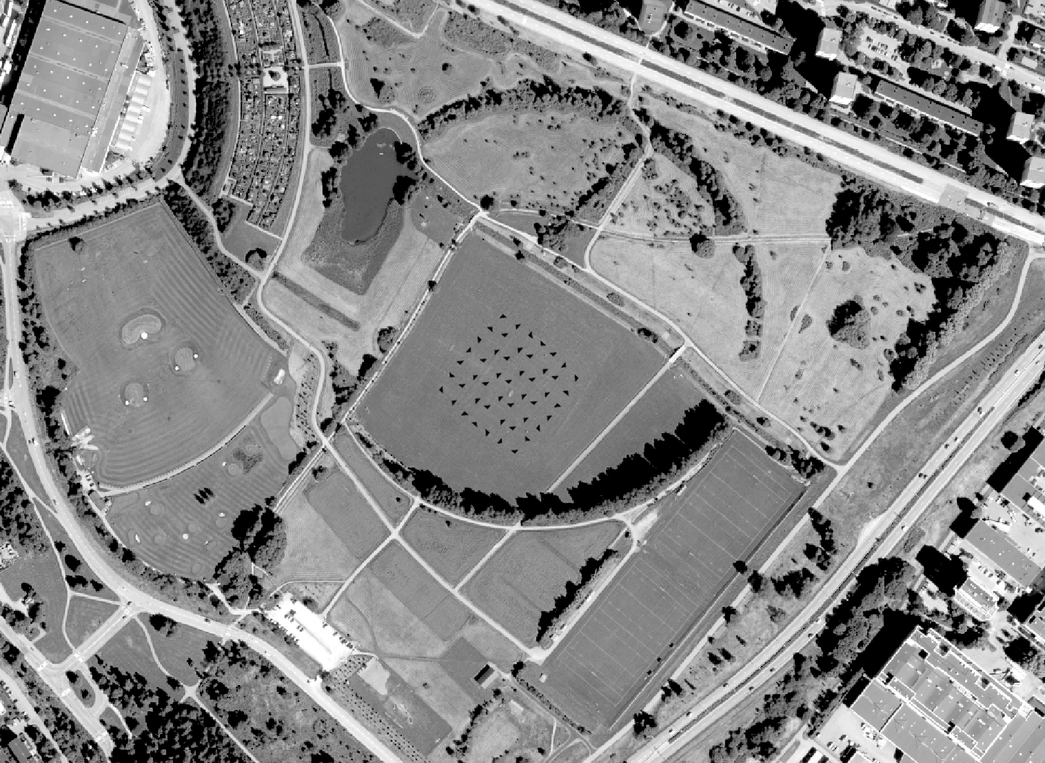
I chose the site from the map of future developments of Årsta and Årstafältet. I am intrigued by the crossroads on the field, since I think they can be used as parameters in the system, as one of the constants that can control the randomness.
In the first assignment I brought some plans that showed a clear modular structure that had subtle varieties and explicit rhythm in its spatial configuration. With this in mind I aimed to replicate a simple element such as a rectangle or a triangle in different rotations but always in a modular fashion. 
My initial experimentations developed into interesting meshes and rhythmic niches that were very useful for my project intentions. However, after the third or fourth variation I realised that these simple for loops were quite limited in their application for what I wanted.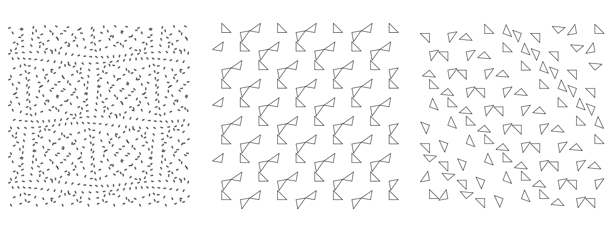
After shifting my attention to right-angled triangles I decided to make and external layer that would serve as the entrance/exit to my plan. Identical on all four sides, it showed some interesting configurations that could direct circulation and exhibition. On the inside I attempted to create a situation as close to random as possible while still keeping a fixed rhythm and relationship between the elements.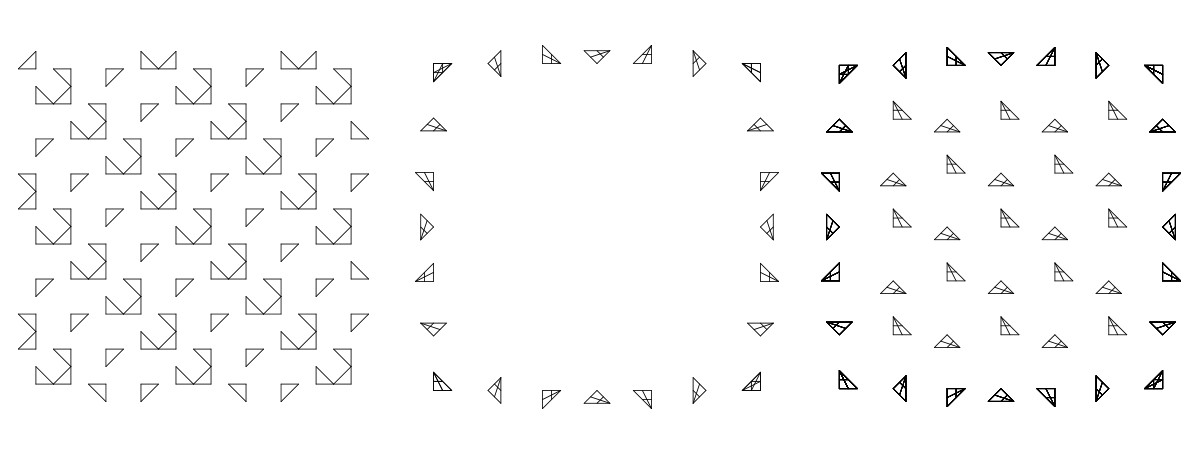
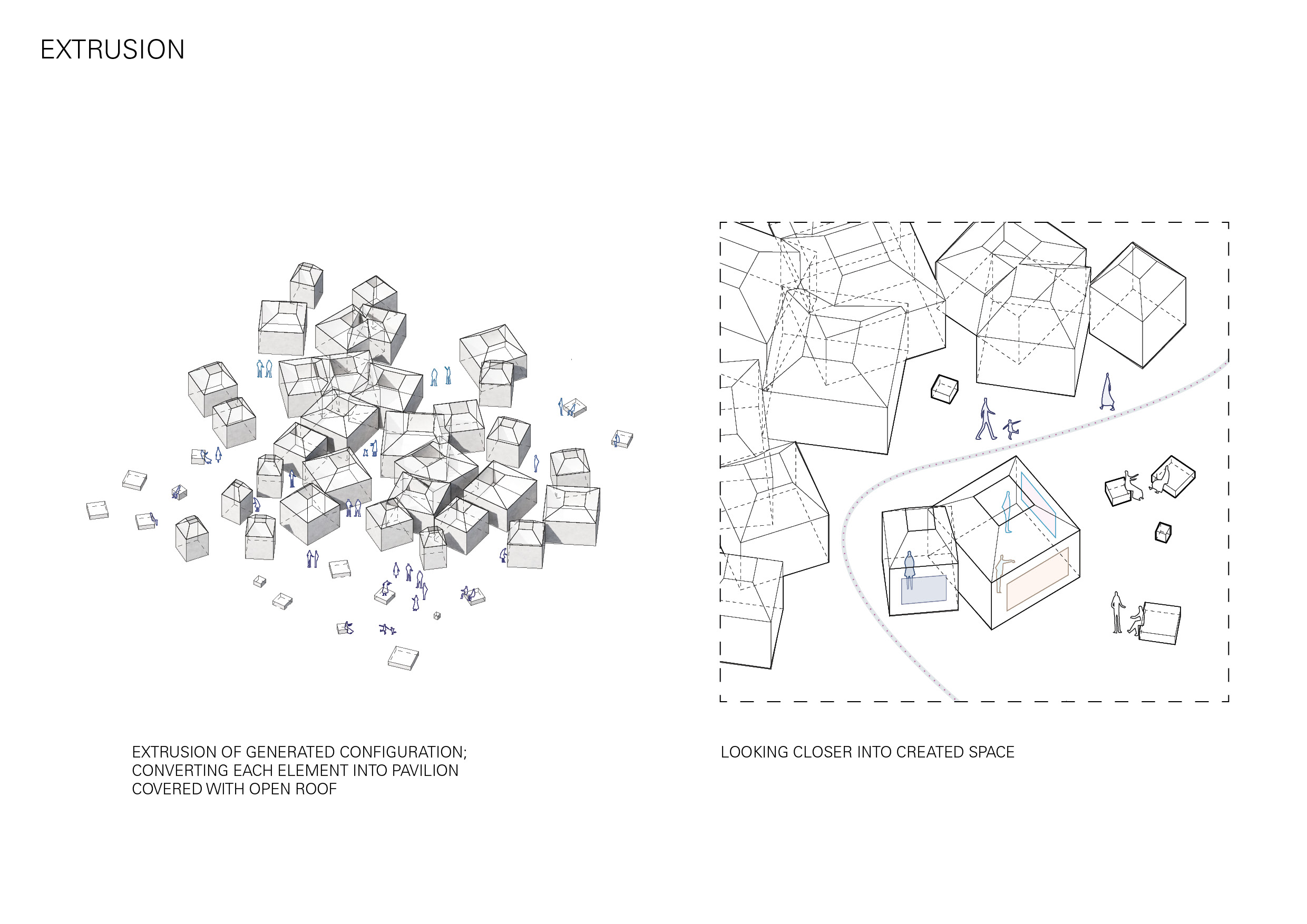
Although I was held back somewhat by my limited Python skills, I found the result very interesting, especially considering these elements as small installation spaces with a lot of circulation between them; almost like a pavilion. For future endeavors, I plan to randomize the spatial configuration some more, as well as creating randomized scales of the same element, which could in turn give me some interesting Boolean differences and relationships with the site.
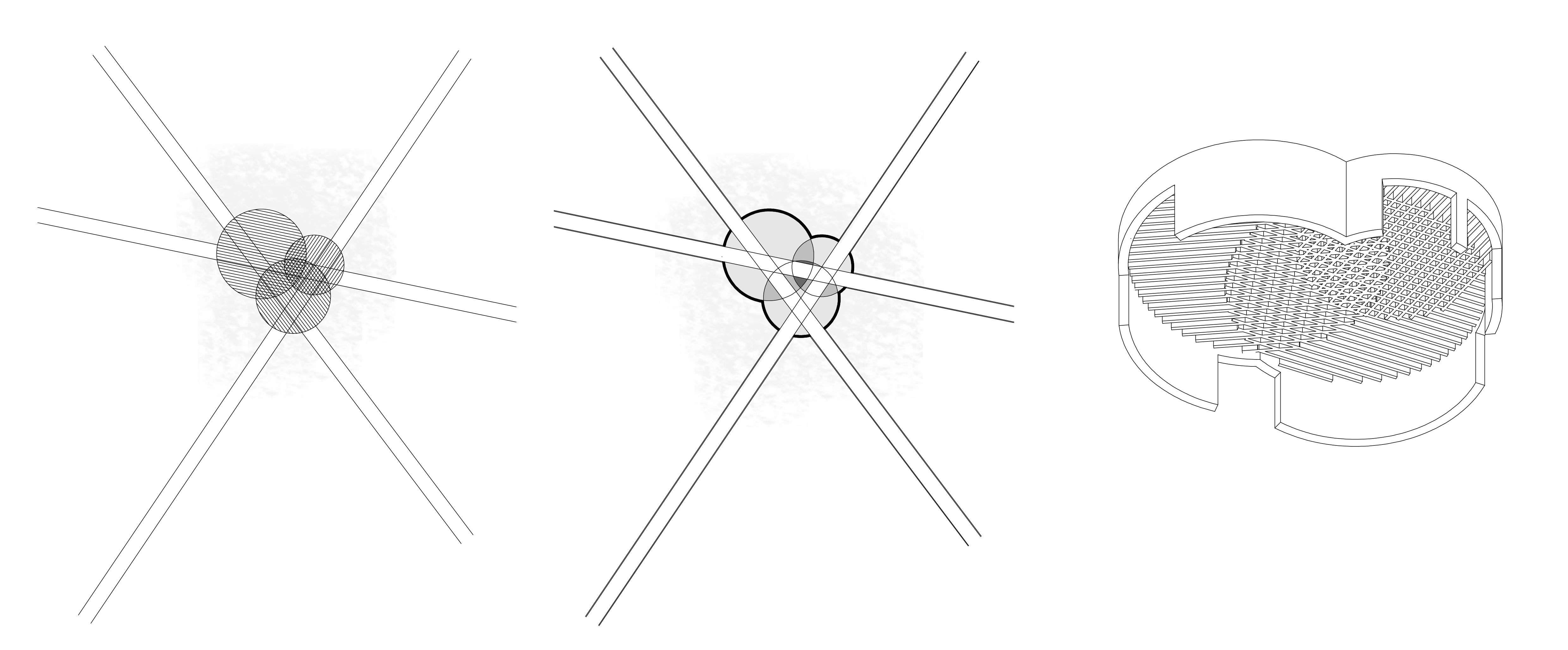
When looking at configurations of precedents, I found two aspects particularly interesting. One was the direct, linear spaces that appear as occupied pathways, and the other is the overlapping of simple geometries to create a dynamic form.
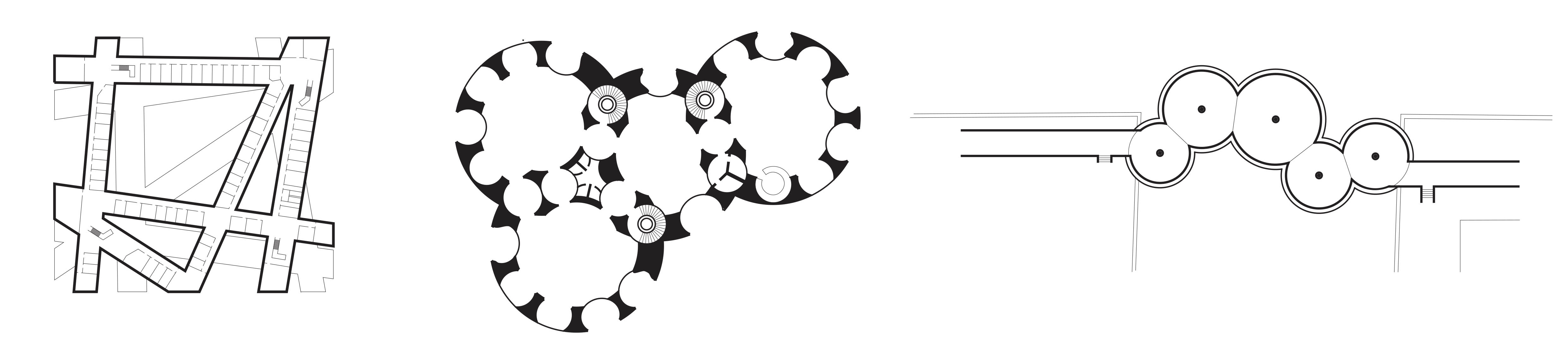
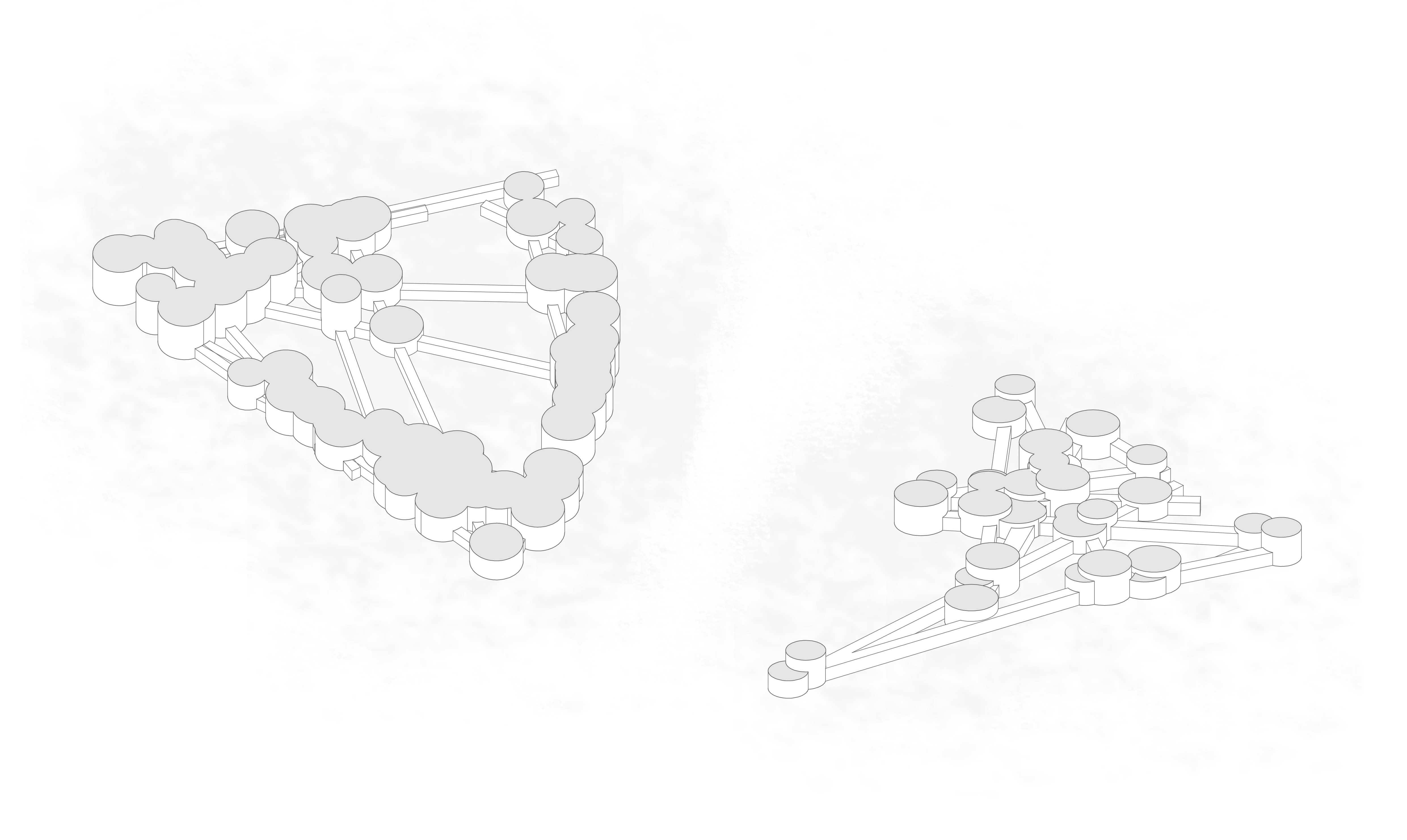
I feel like the first one is a missed opportunity for some interest or excitement in locations where these paths meet. I began by working with a simple box boundary, dividing the boundary into points and connecting them. These then cross over each other, and I have added circles at the intersections.
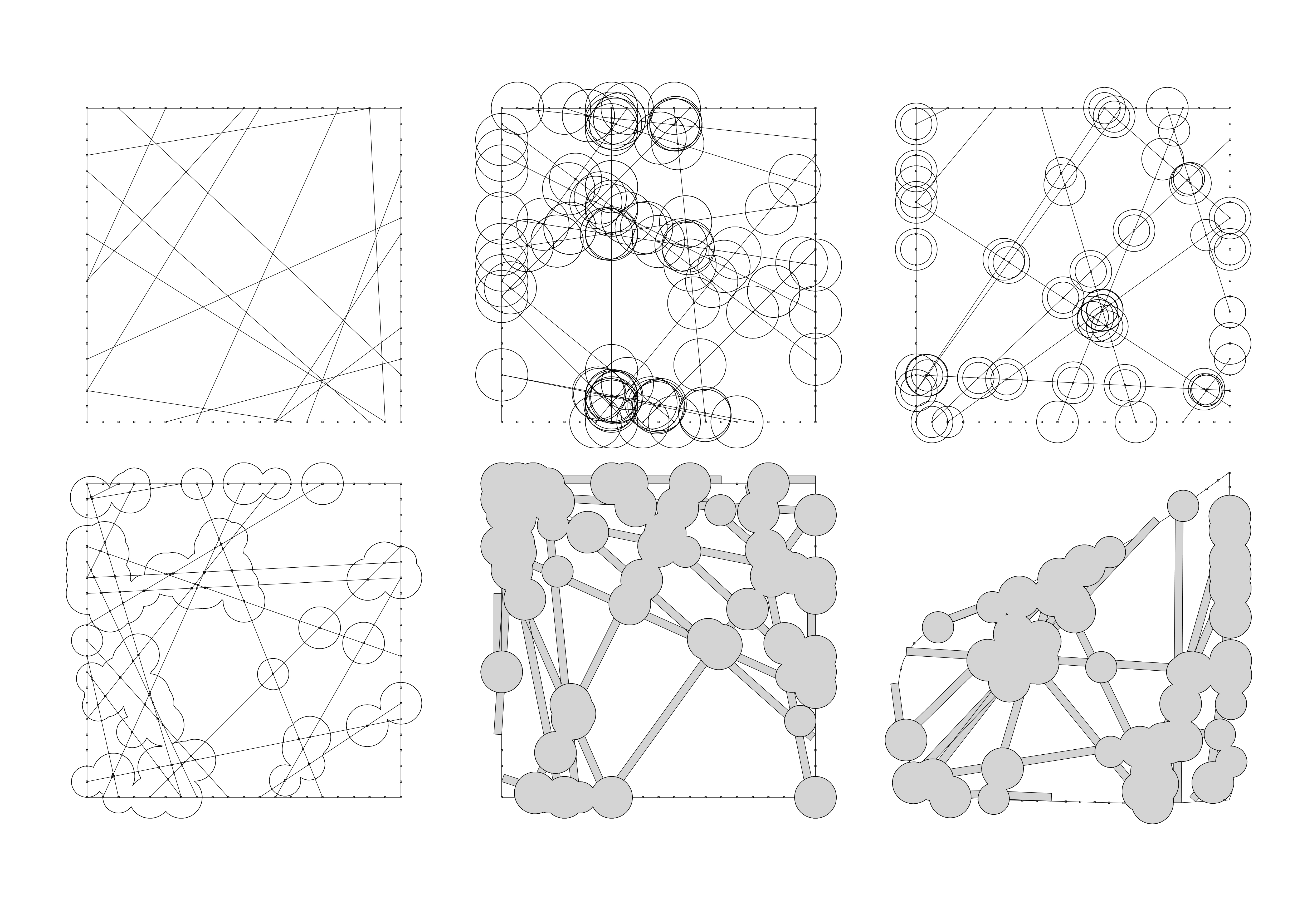
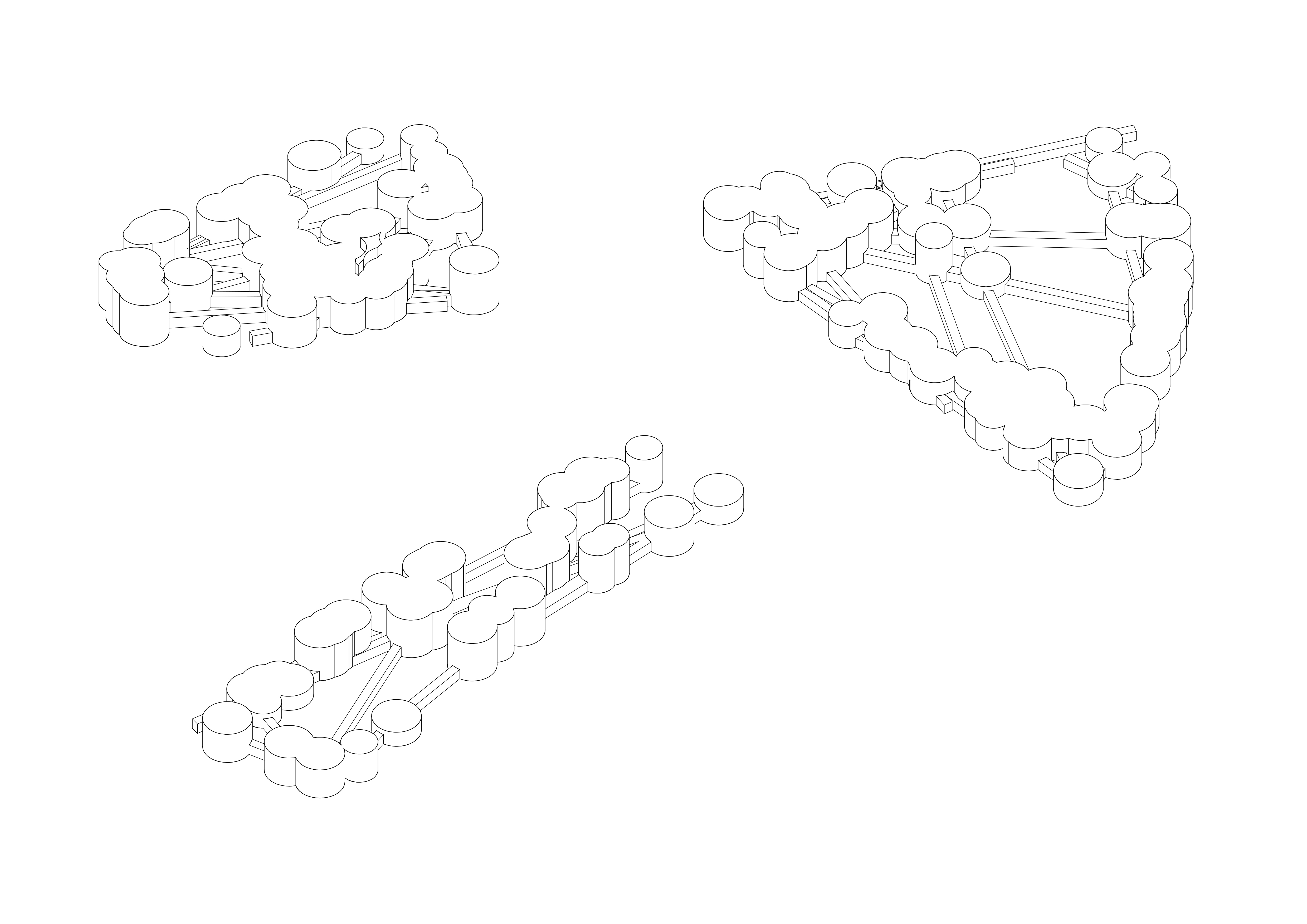
By randomising these circles, cleaning up the overlap and forming paths out of the lines, I have created a configuration, which can then be applied to any boundary curve. In 3D, it starts to form something like this:
And finally, an example on site:
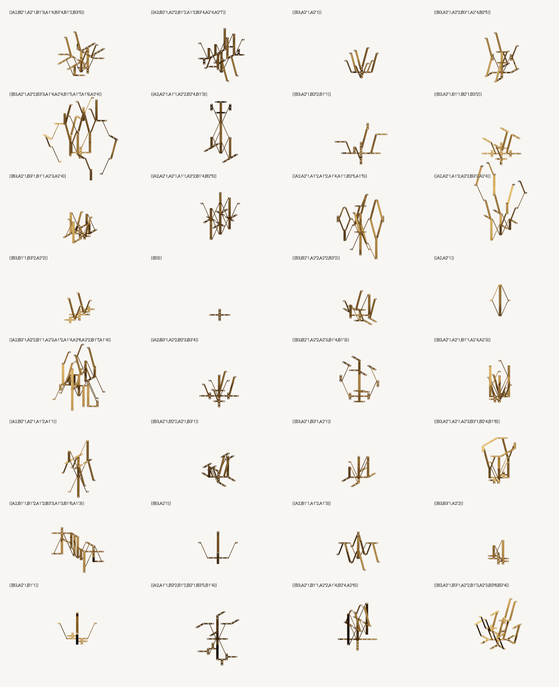
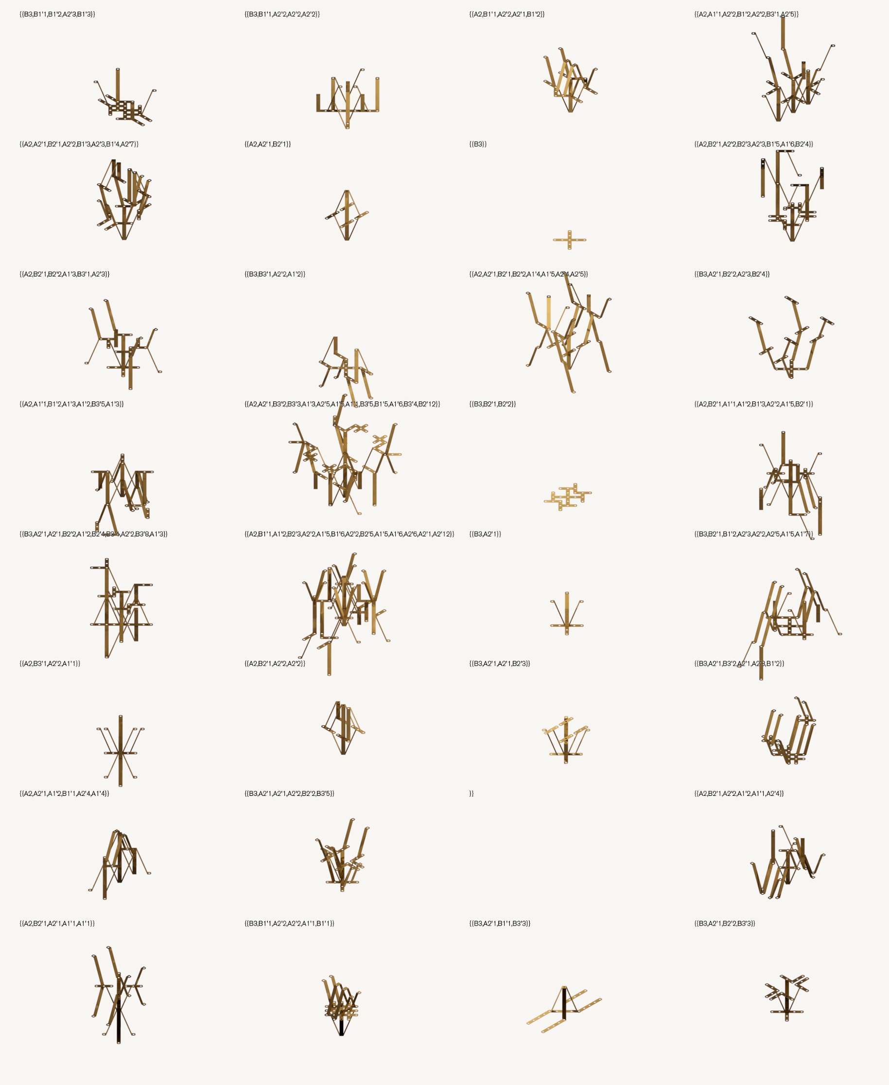
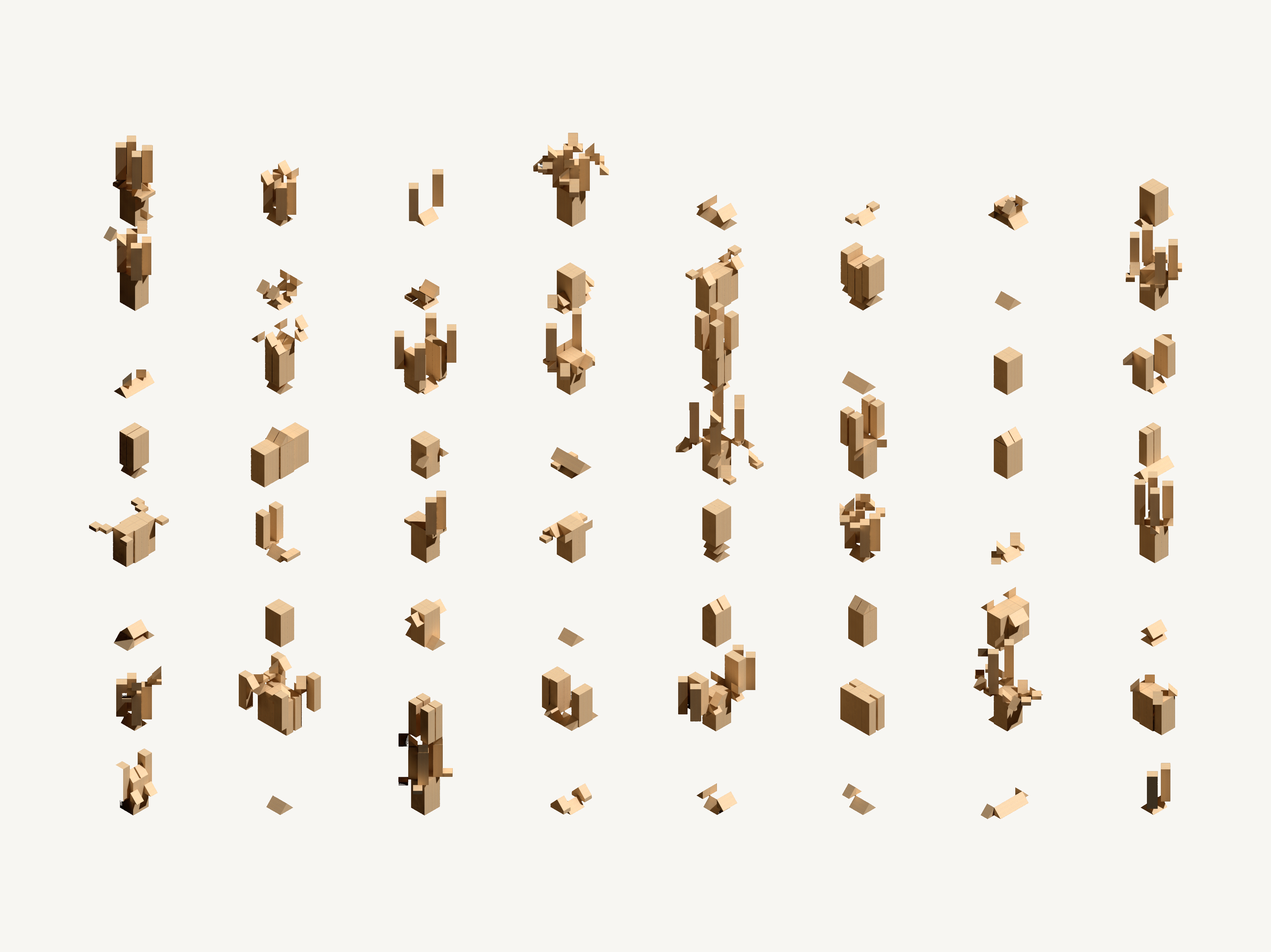
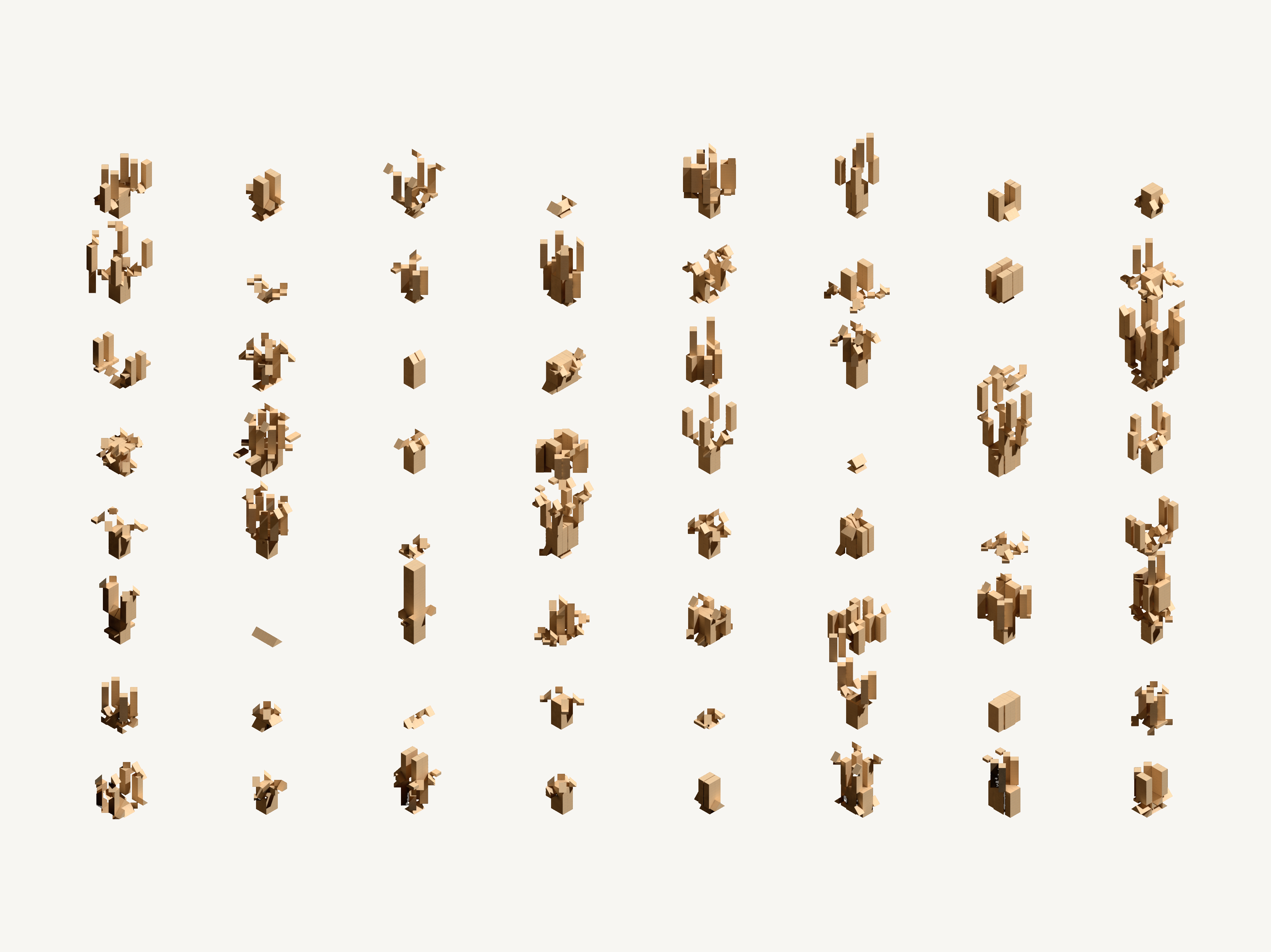
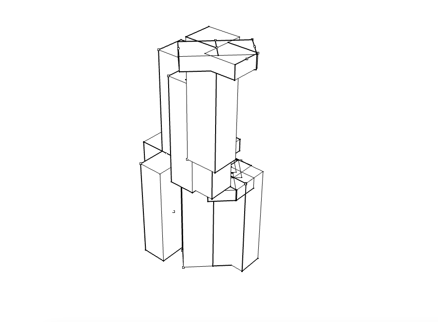
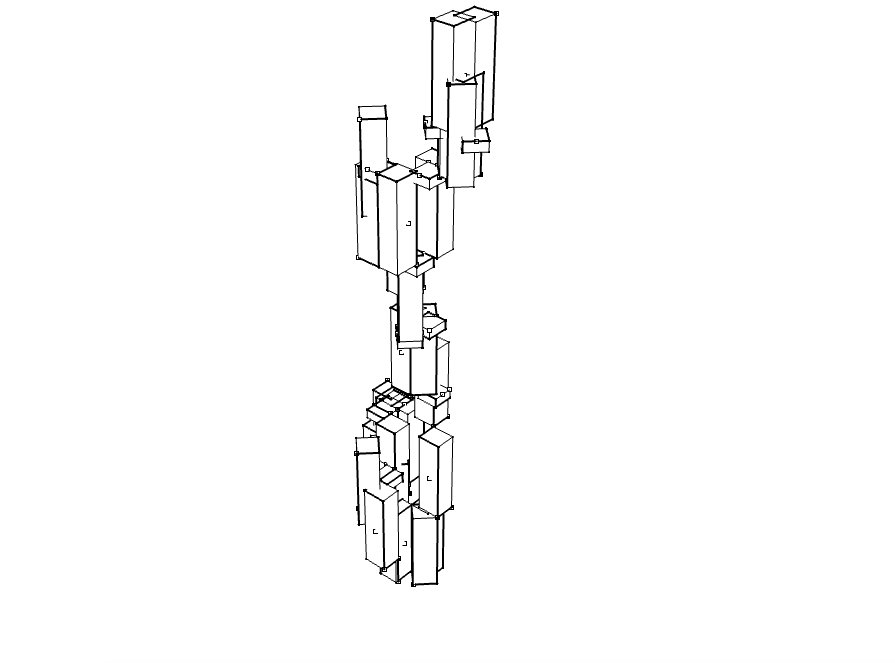
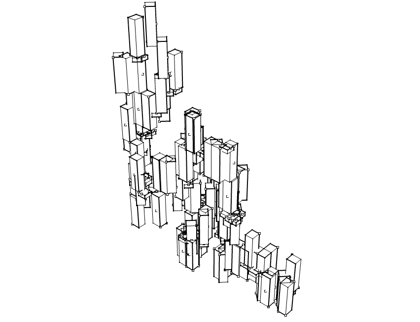
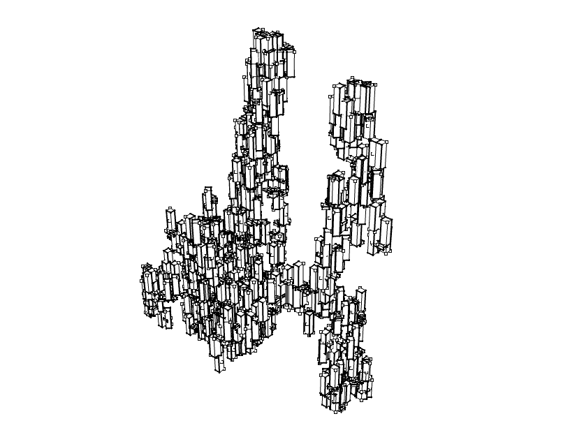
Rule-Based Component Aggregation with Constrained Rotation, Reflective Symmetry and Collision Detection | September-October 2017
This project resulted in the development of a geometrically general but compositionally constrained system for component aggregation in the Rhinoceros 3D / Python environment. Components and connection points are defined as blocks in Rhinoceros, and parameters for aggregation rules, rotation constraints and levels of symmetry are given as Python variables.
Random Populations and Notations
Random Populations
Studies
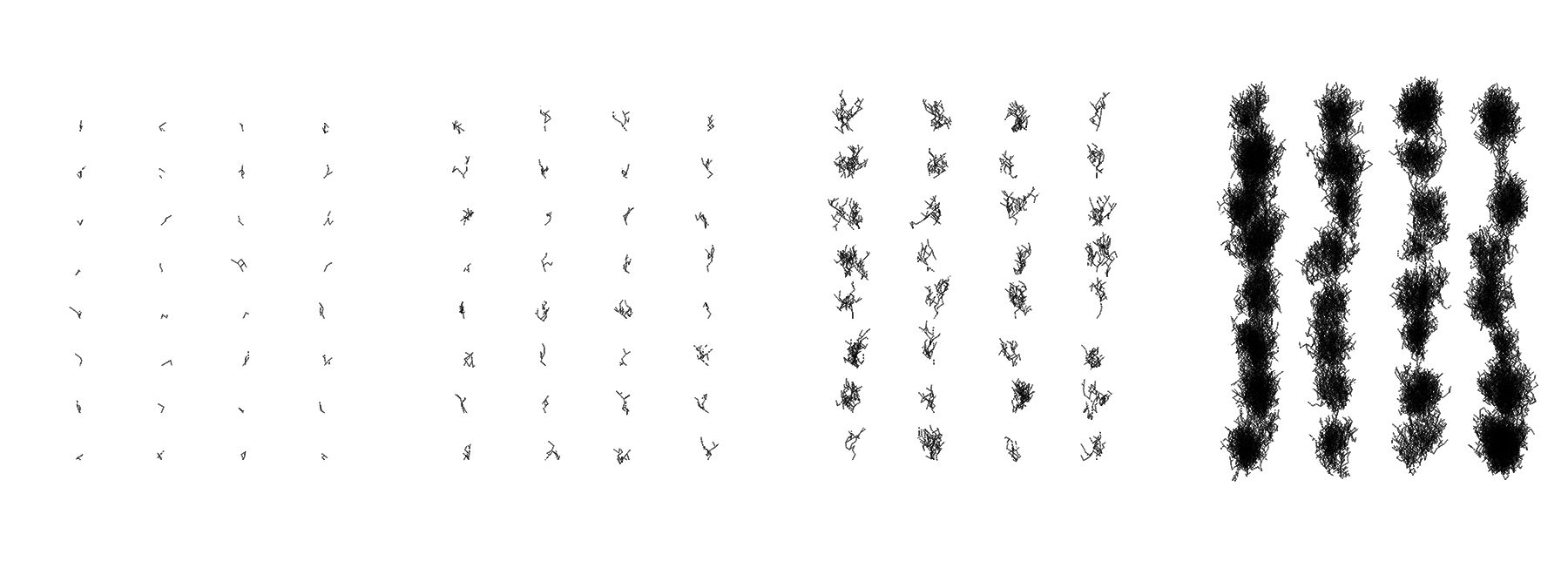
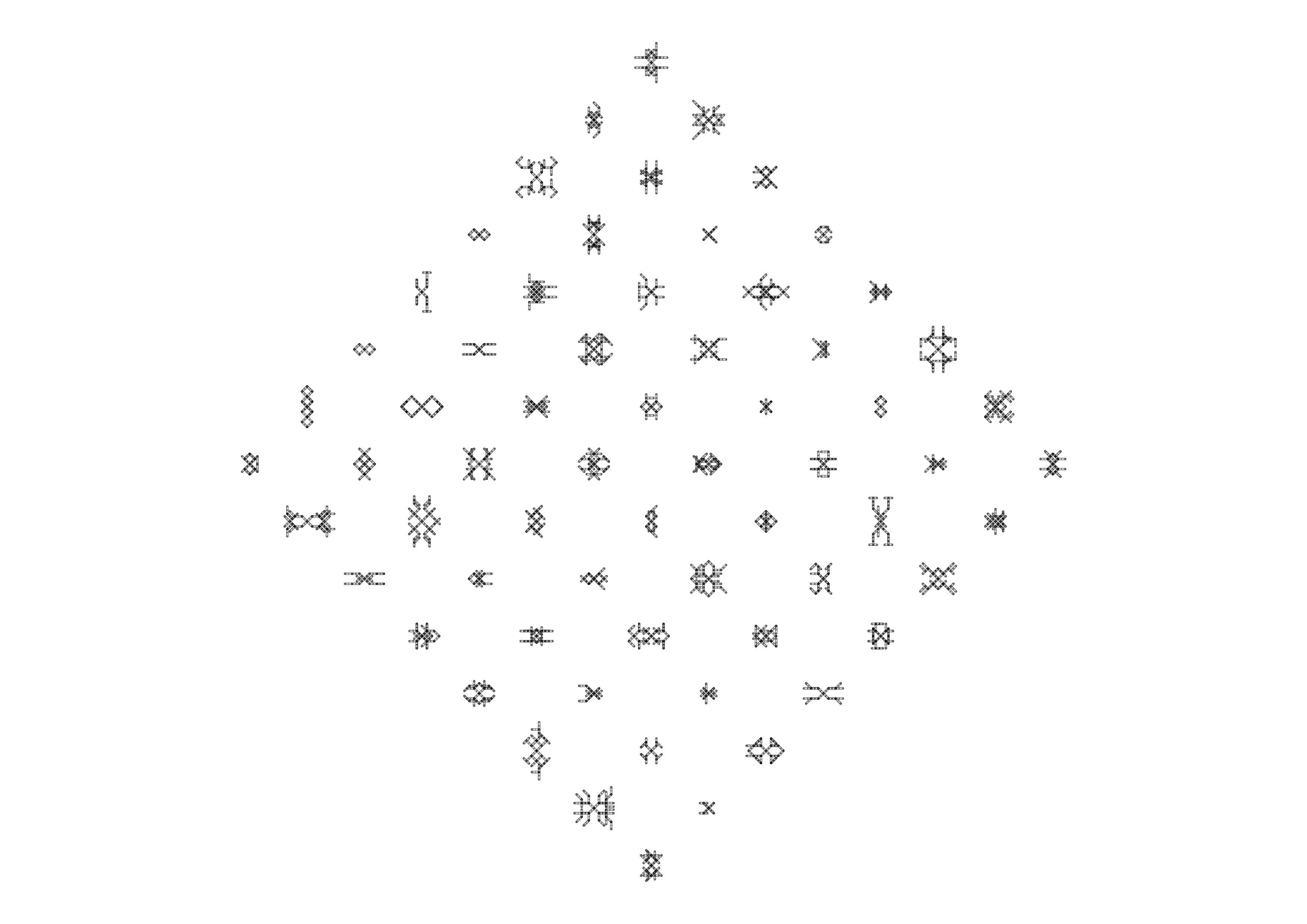
Iterative Cursor Growth
Below you will find all the webinars by David Rutten, the creator of Grasshopper:
Introduction to Grasshopper with David Rutten:
David Rutten’s Introduction to Grasshopper Webinar:
Advanced Topics in Grasshopper:
