Manipulating the roofscape

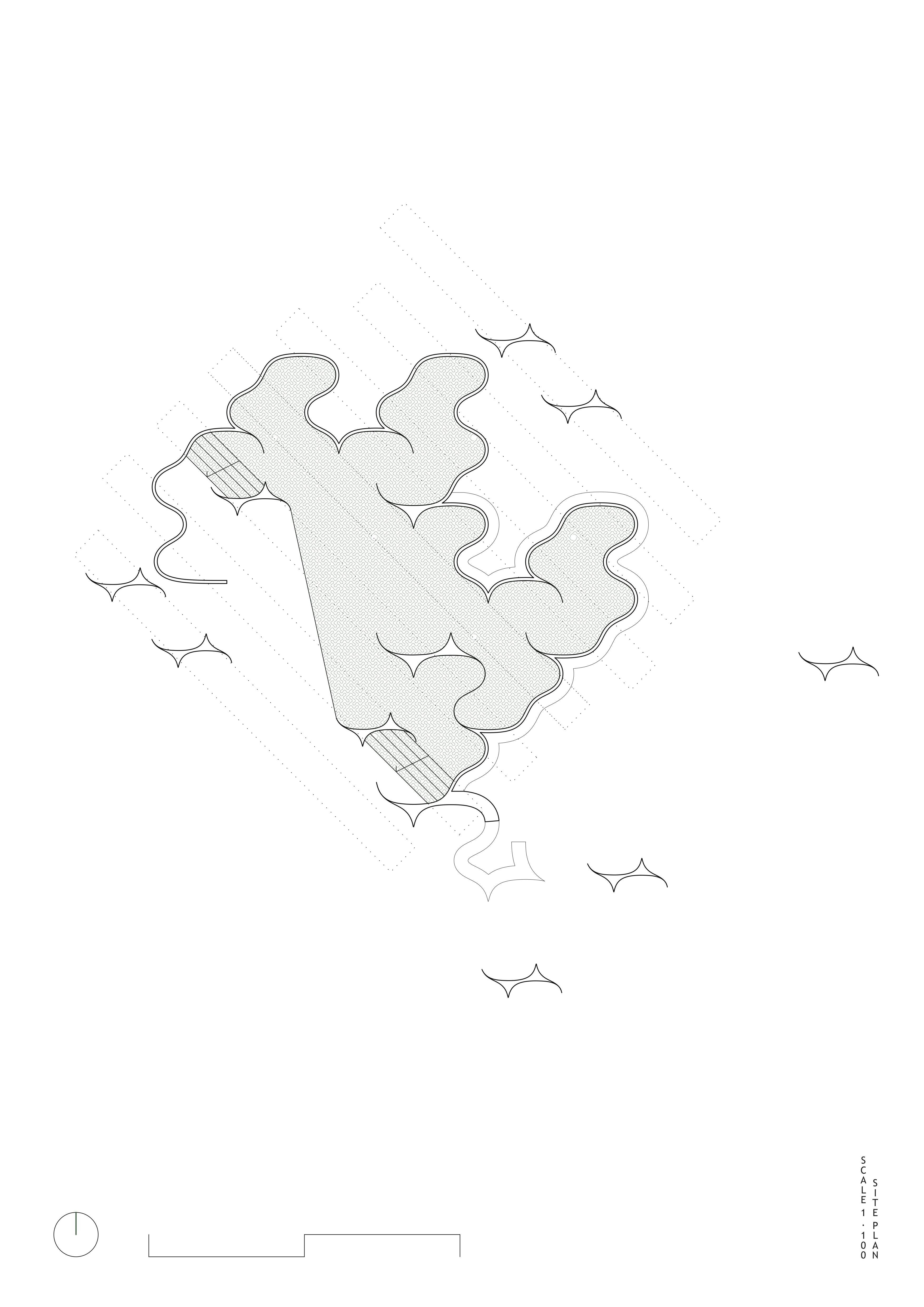
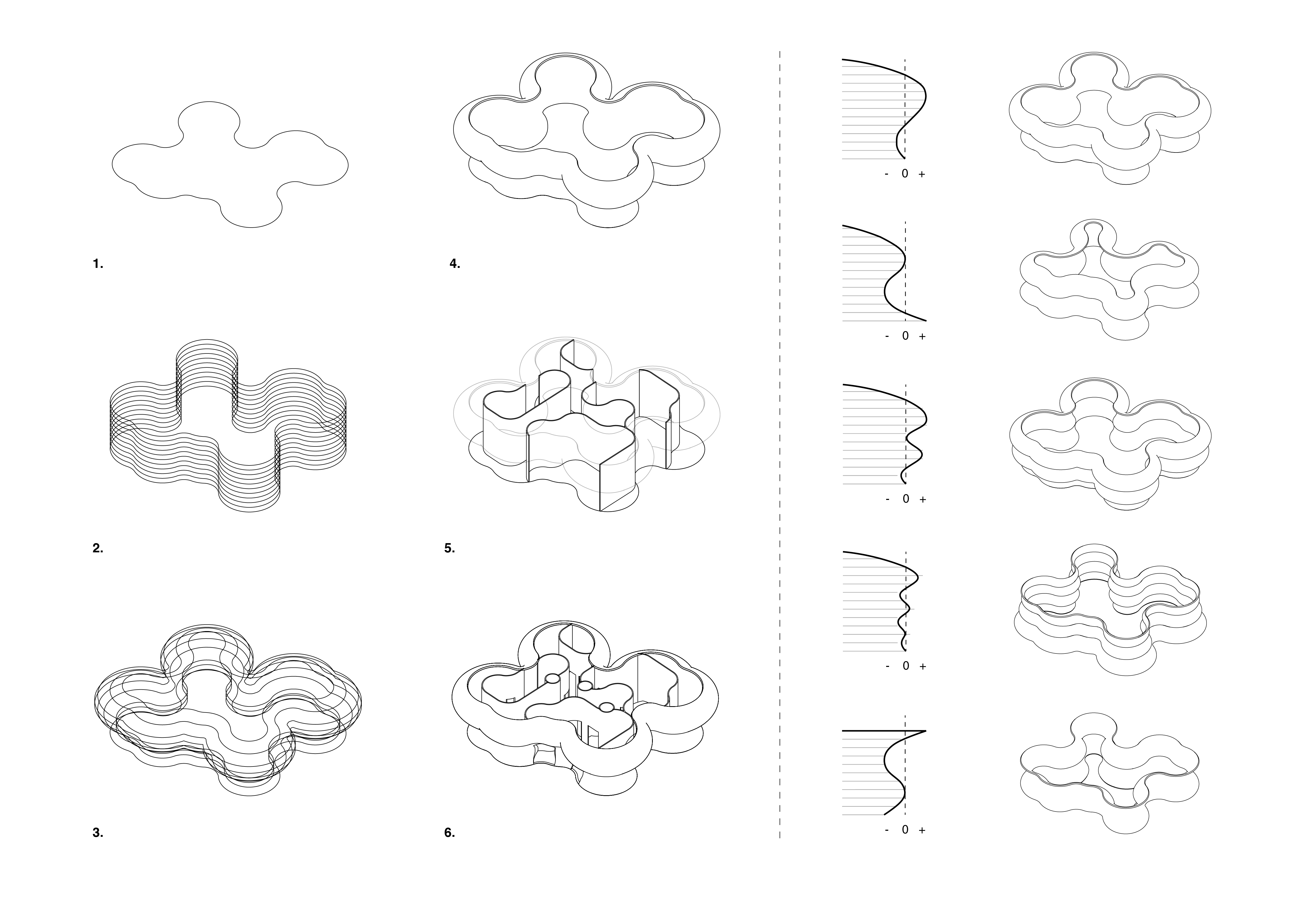
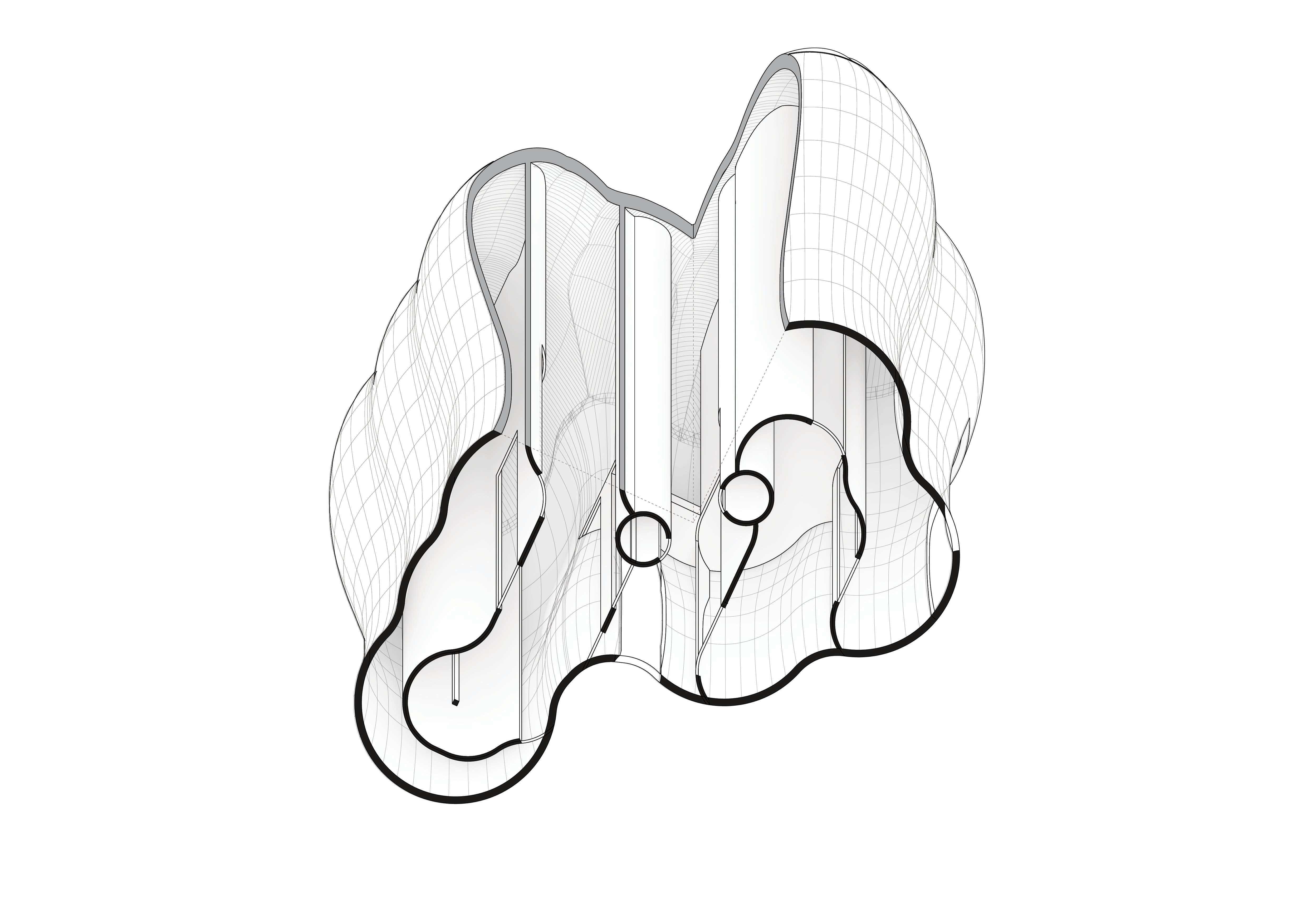
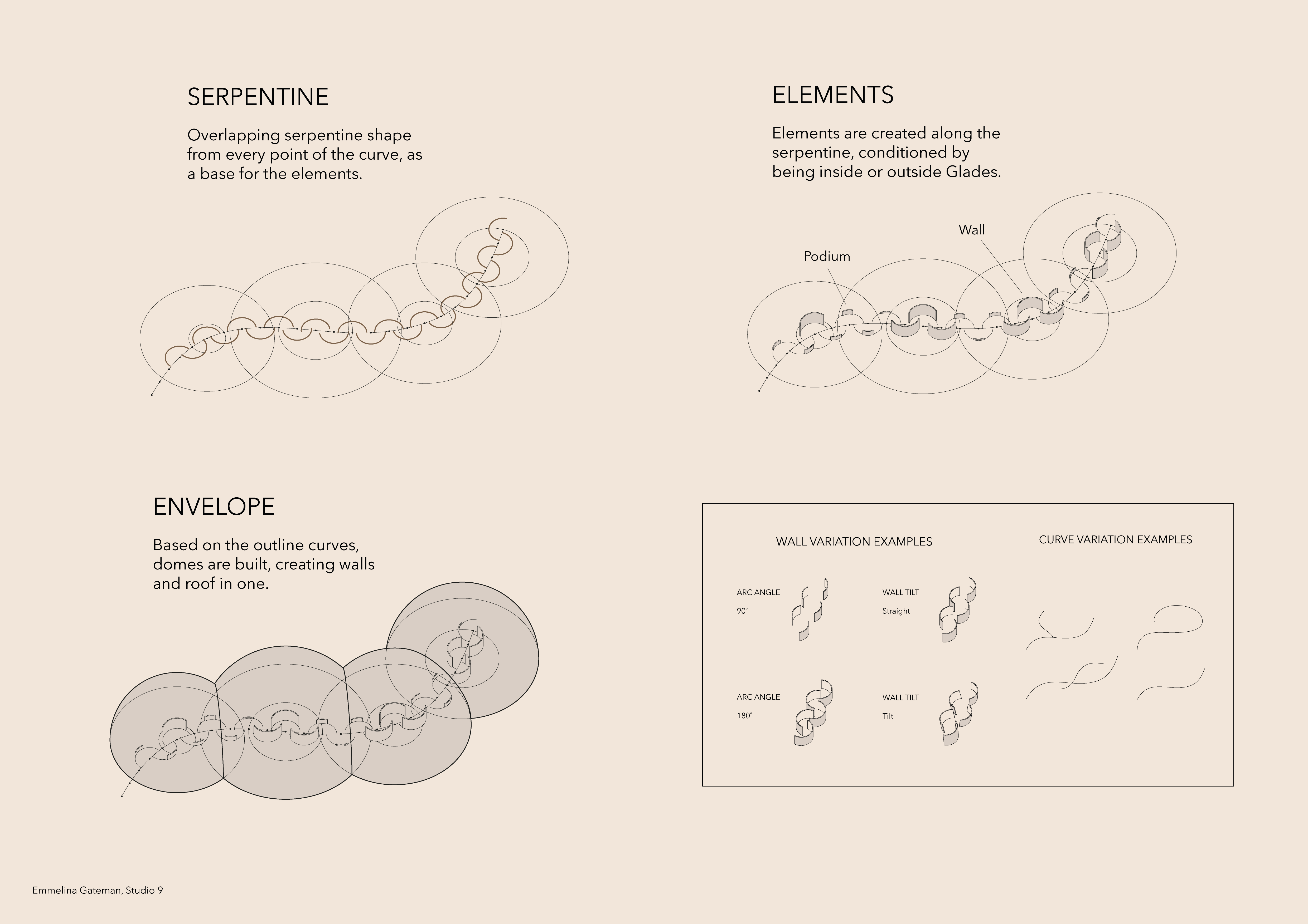
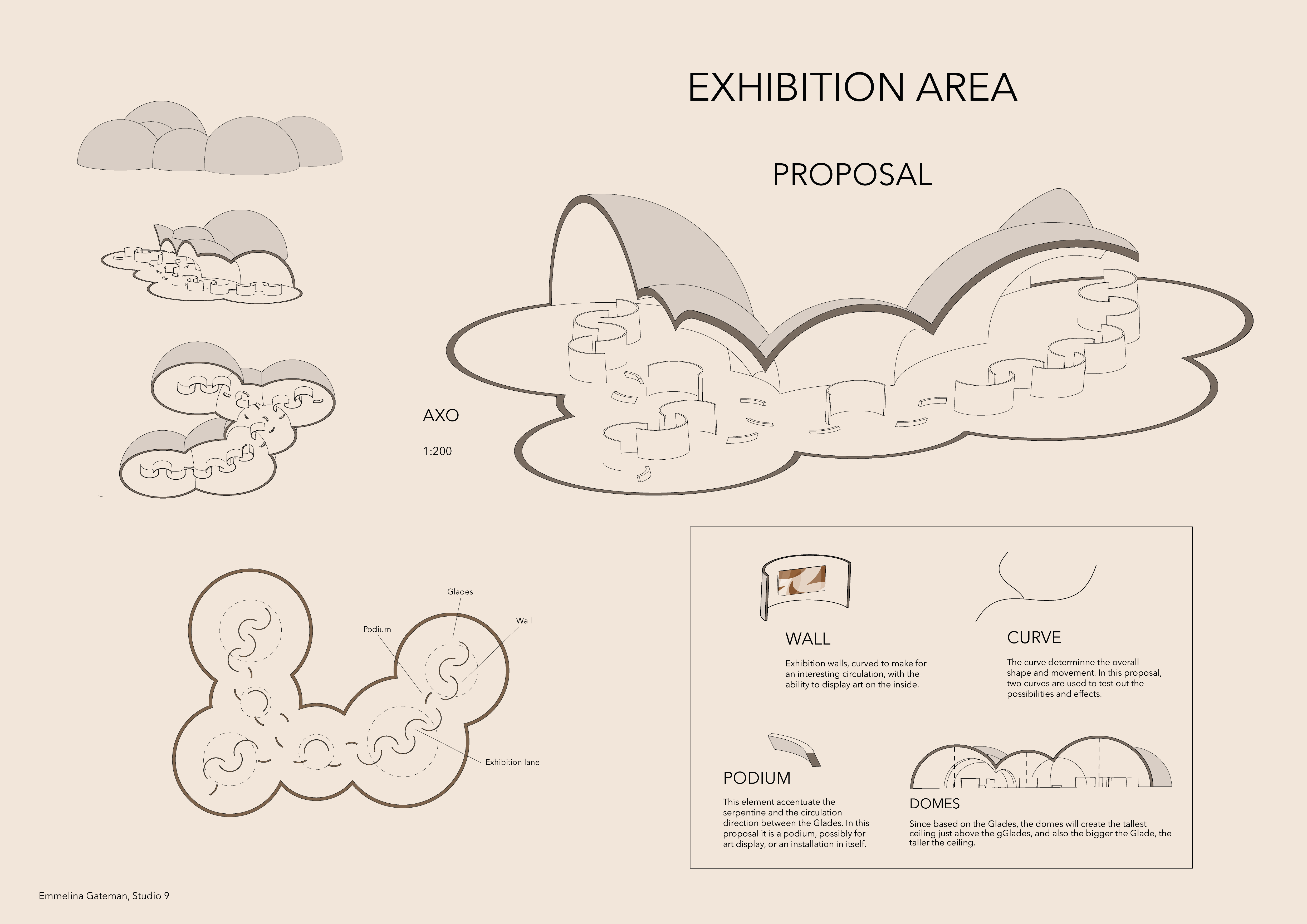
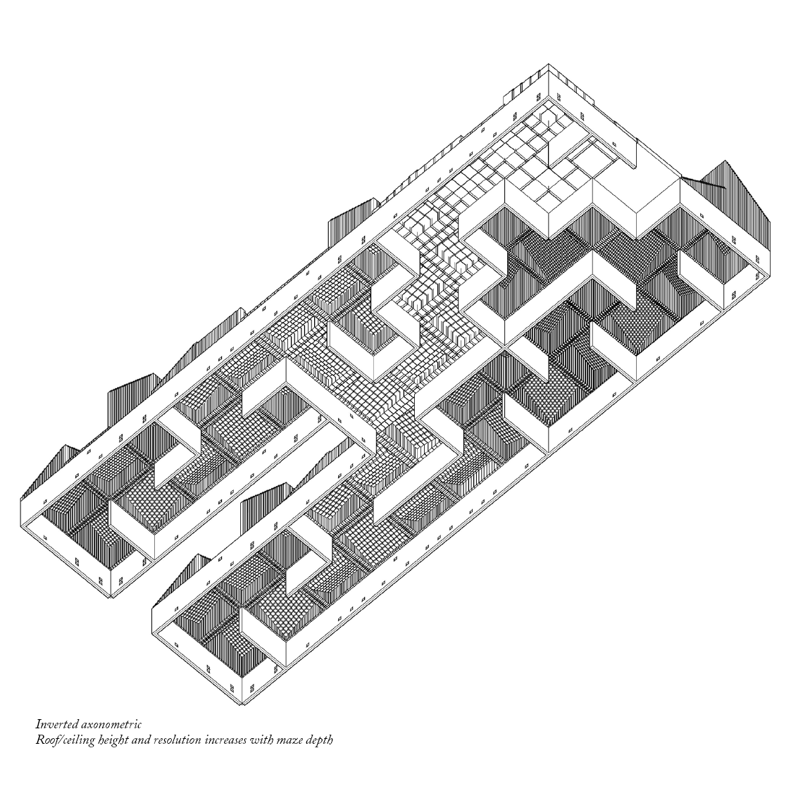
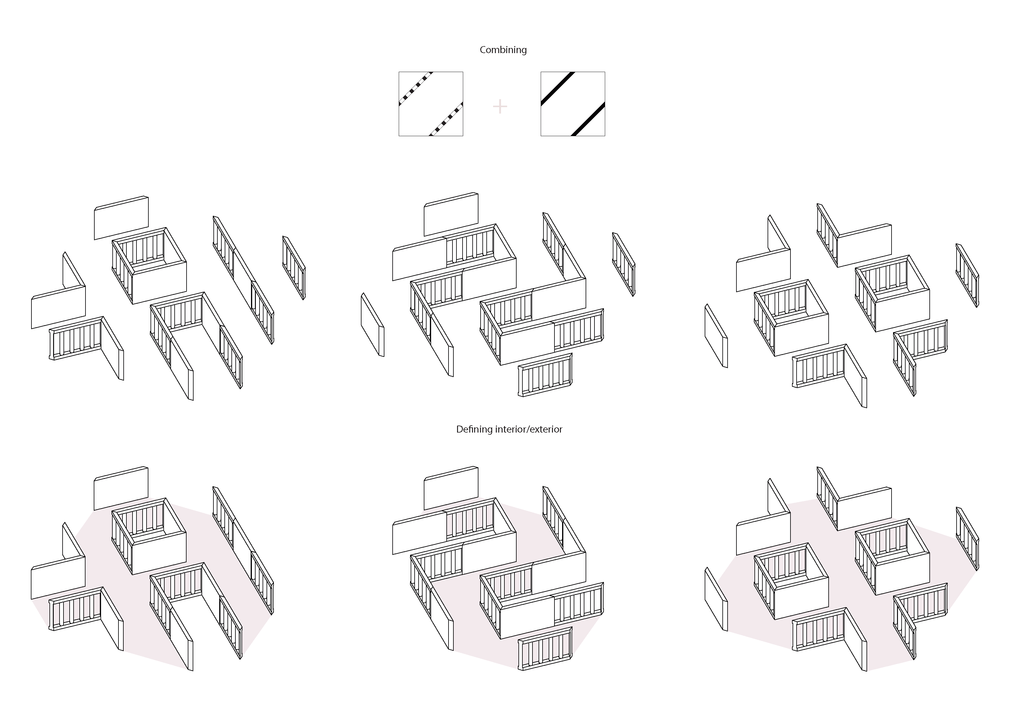
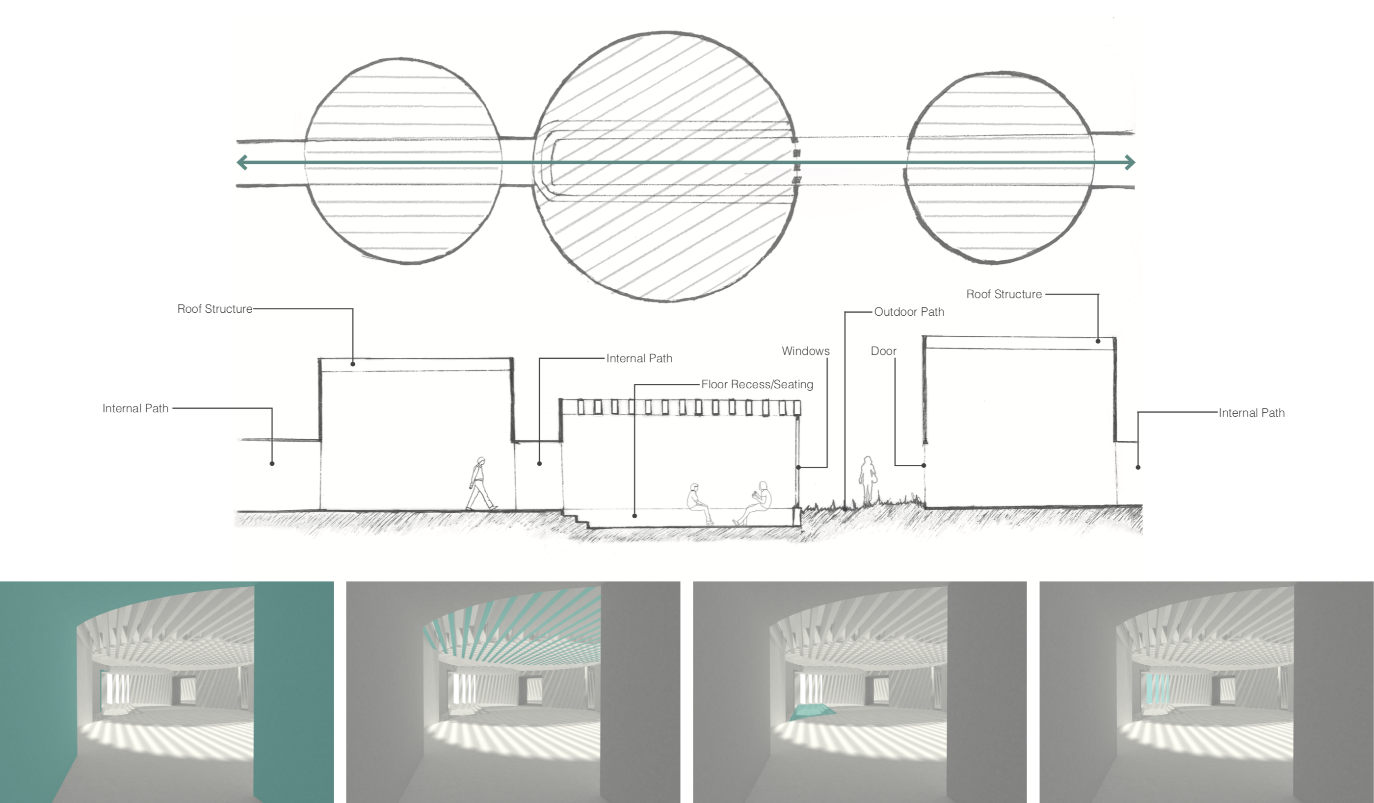
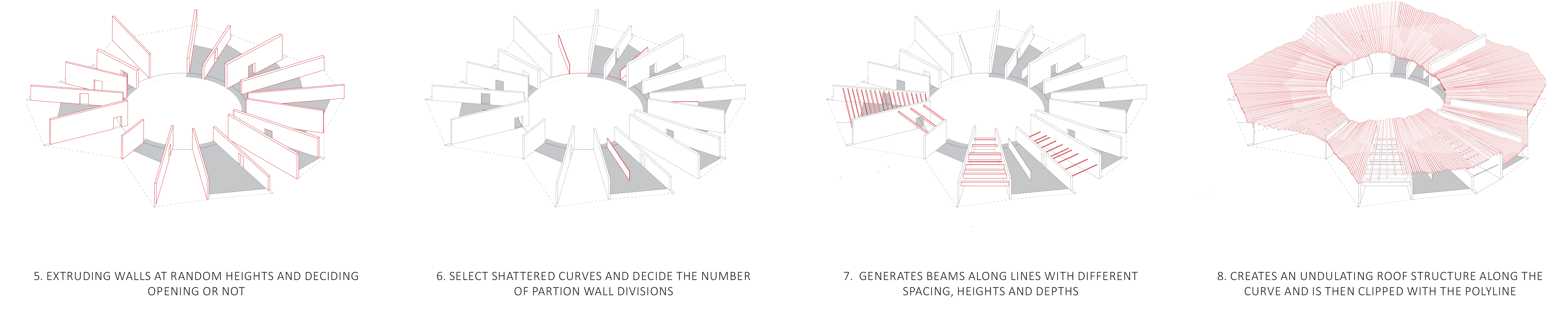
After producing the axonometric development drawing , I used this as a snapshot to analyse how the code was generating spaces and controlling circulation. But most importantly to reflect on how the walls, beams and roof were working together through manipulation of the code. I started to alter the logic of the code to create a controlled circulation route through the spaces. By randomly deciding whether to shift a wall and creating an opening, or leave the wall untouched.

Final presentation.indd

Final presentation.indd

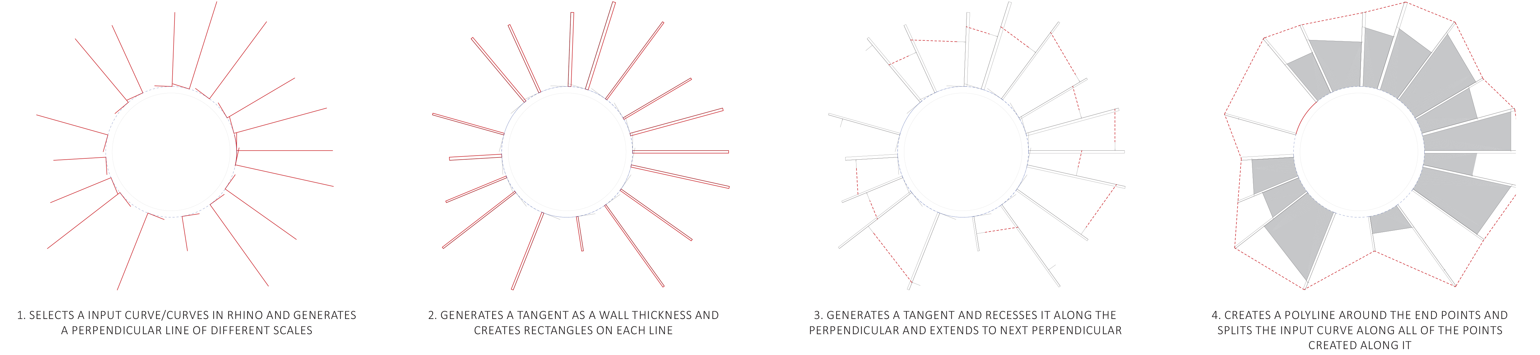
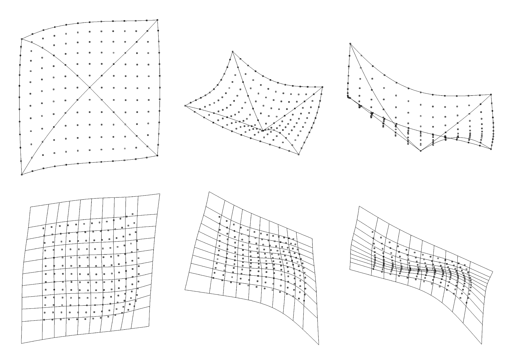
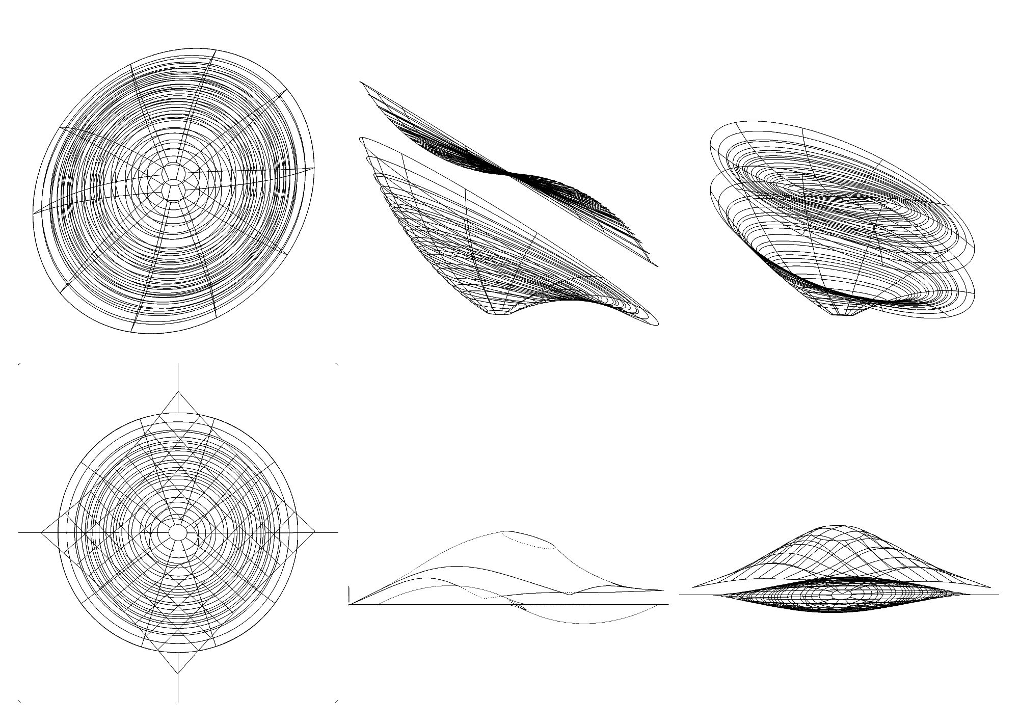
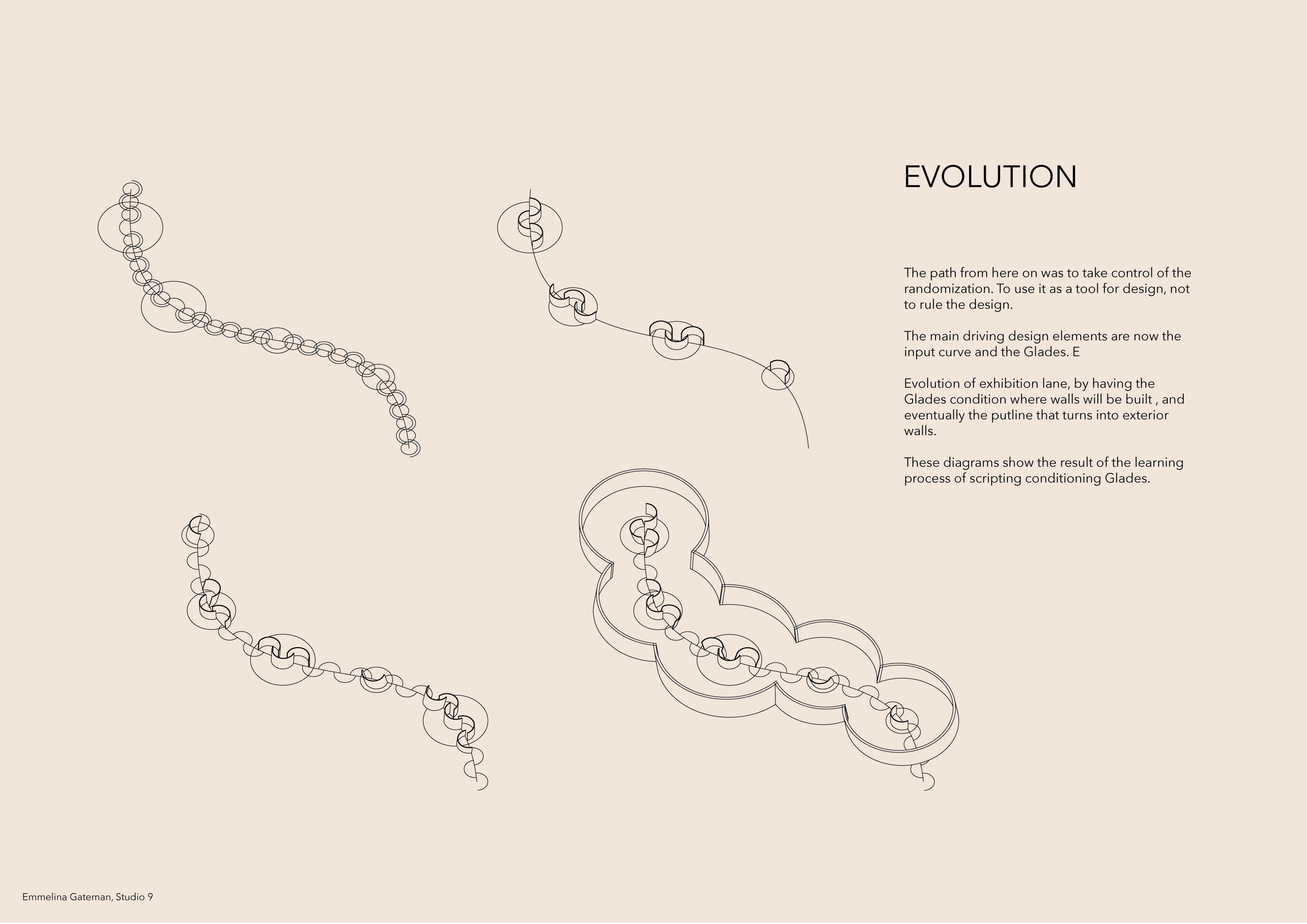
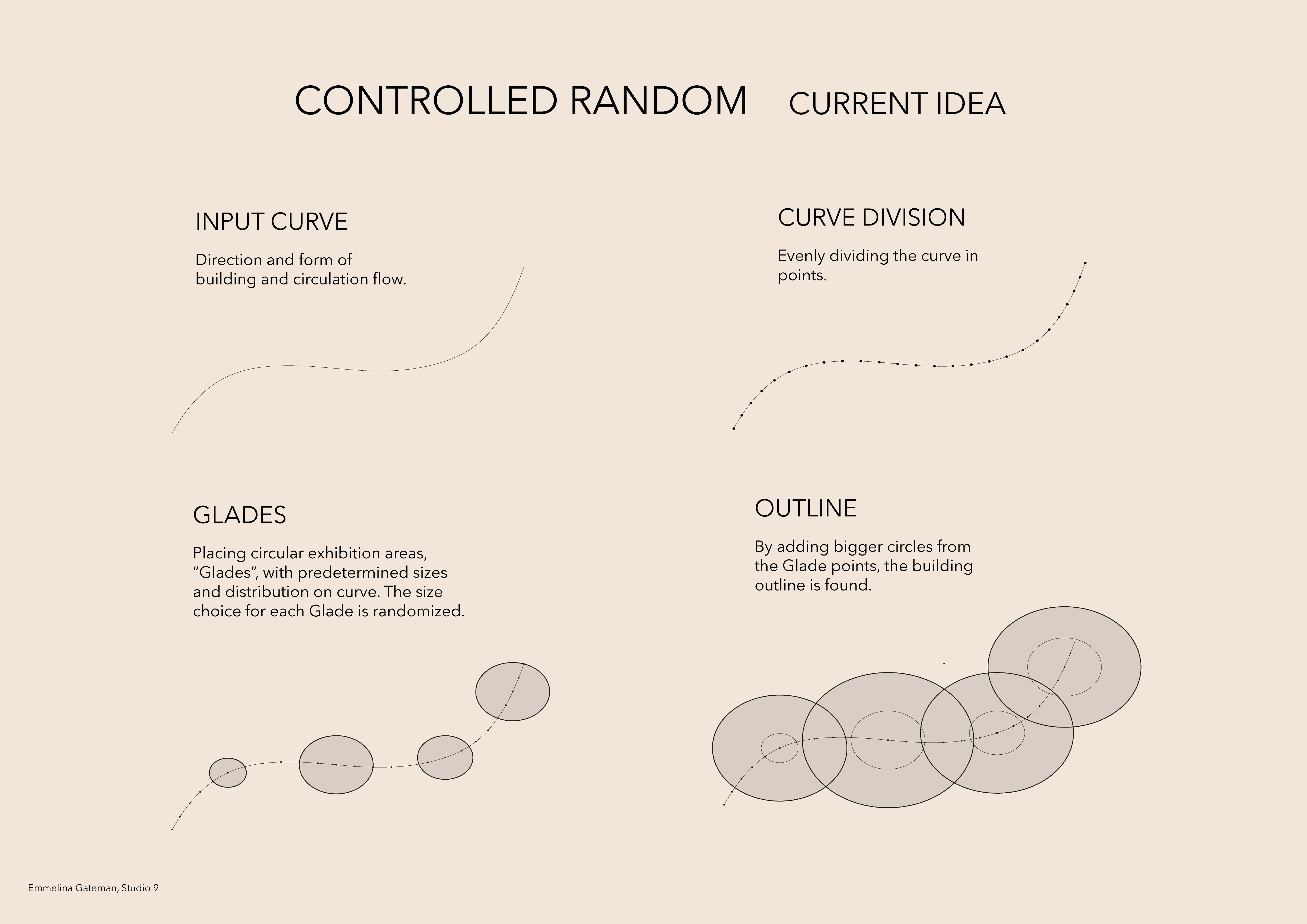
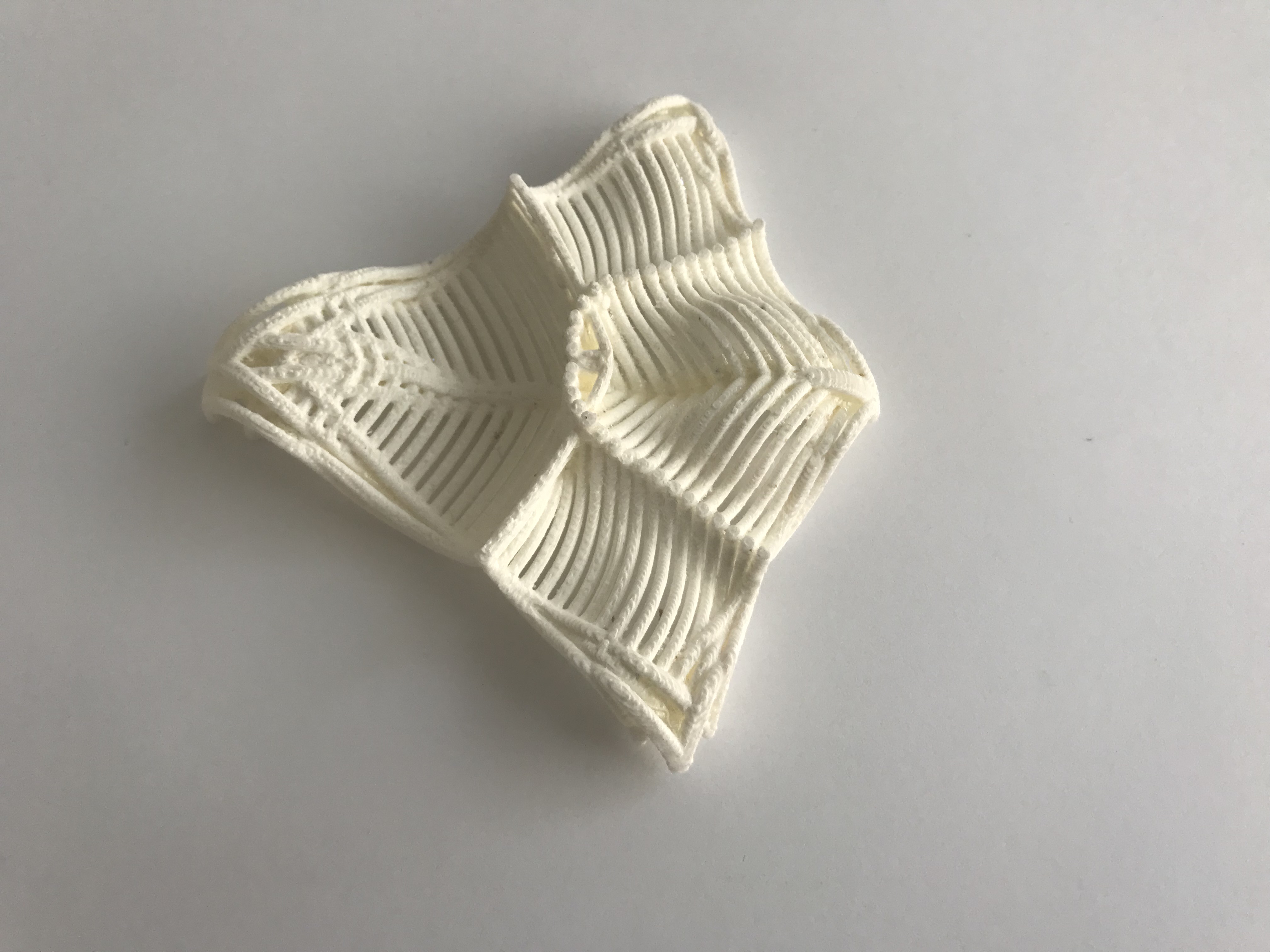
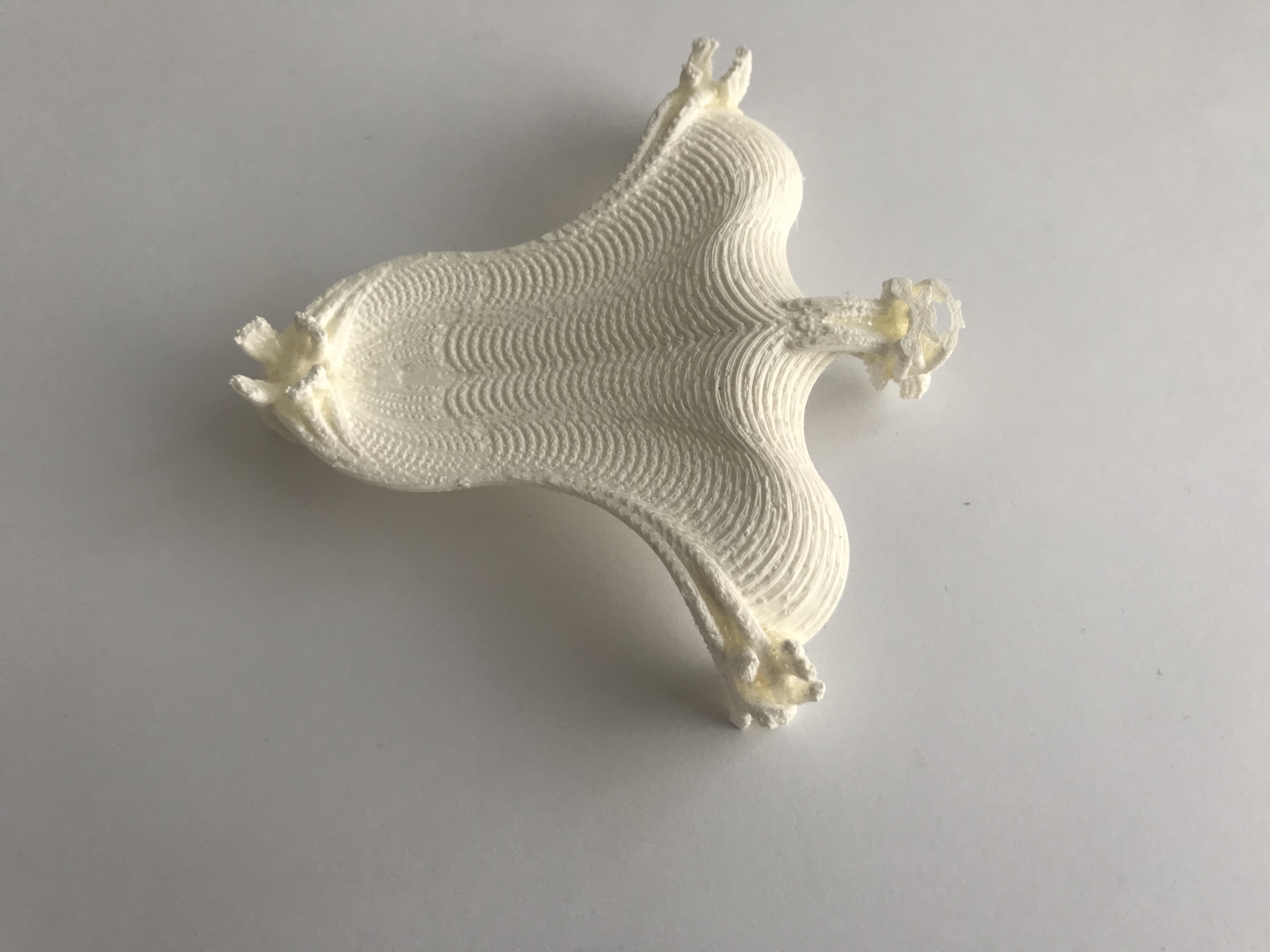
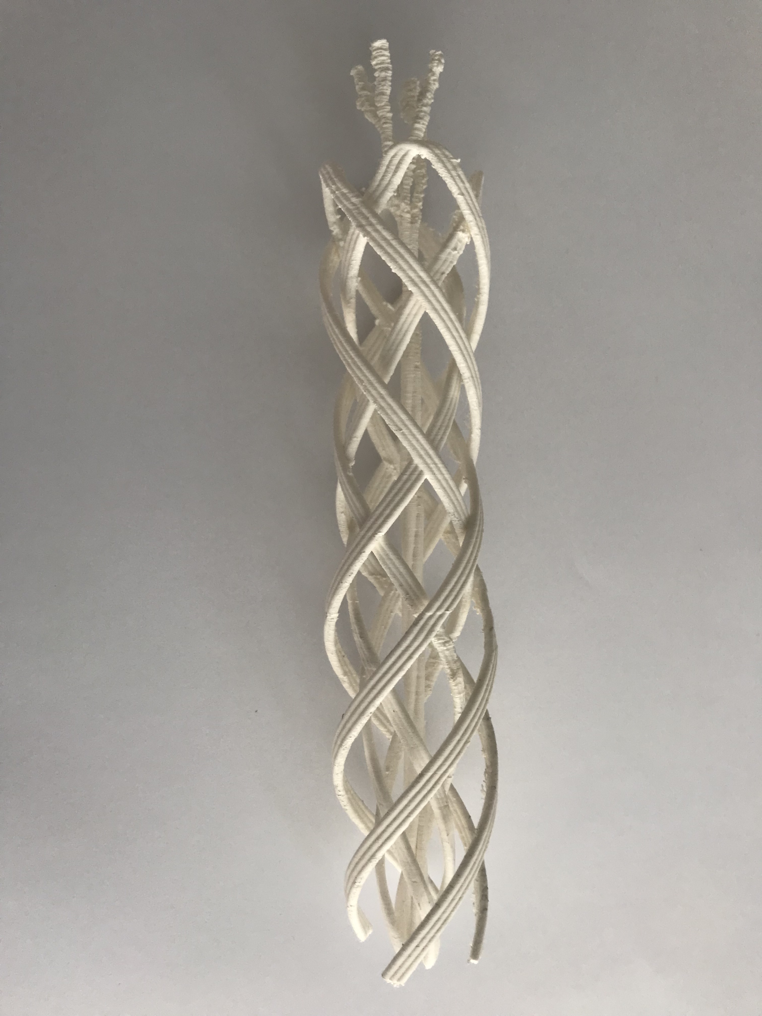
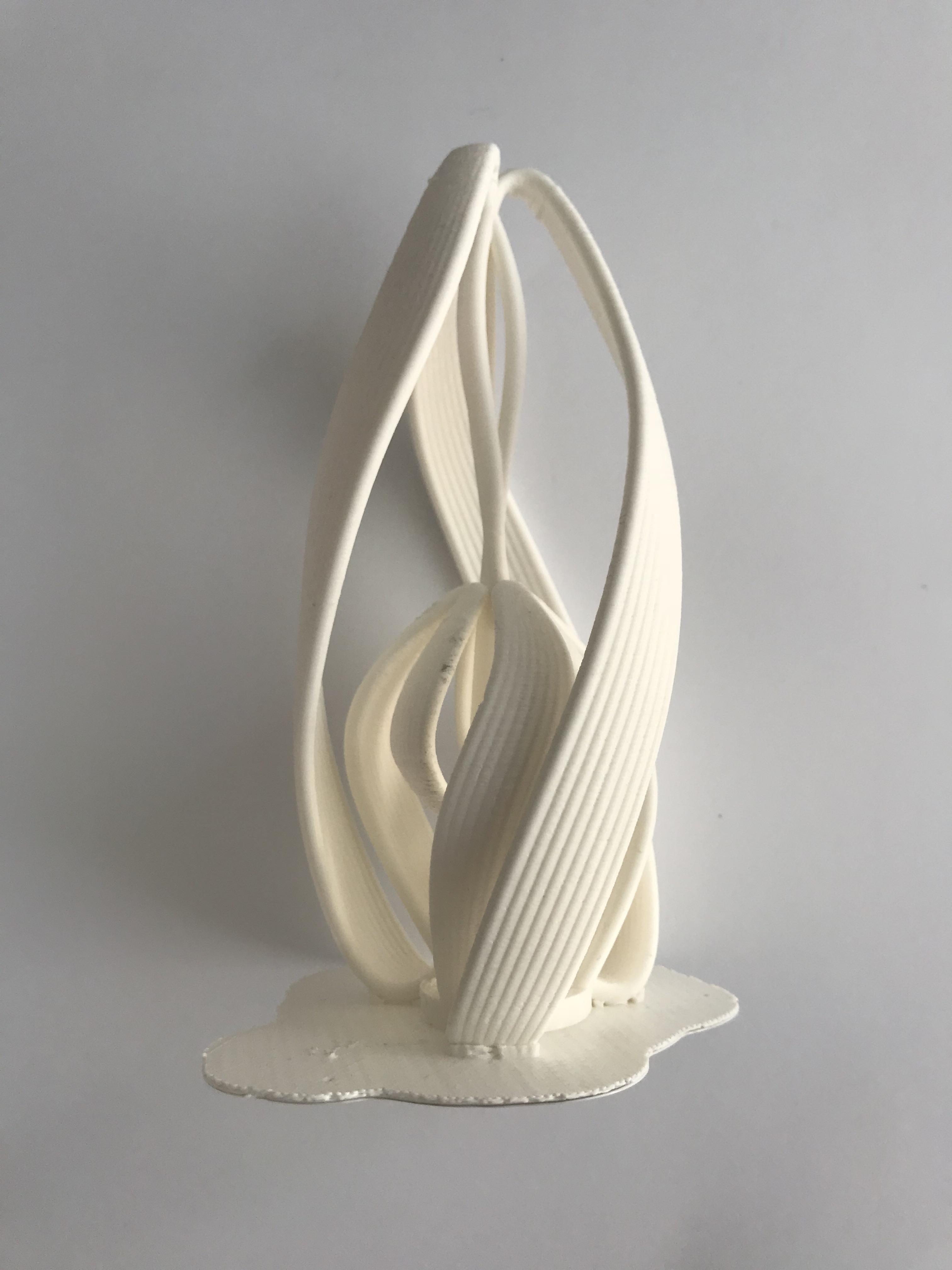
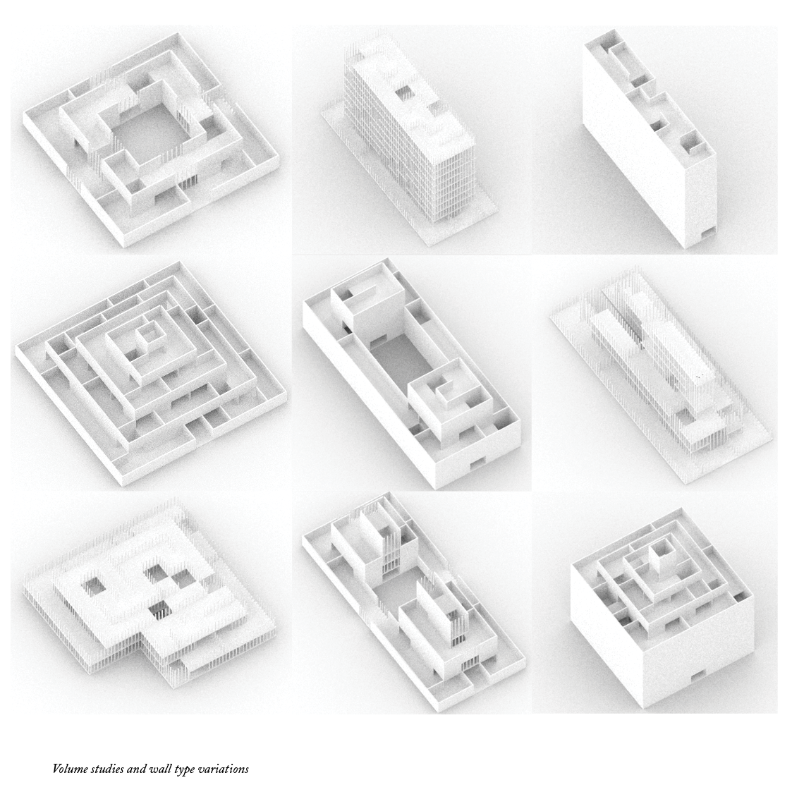
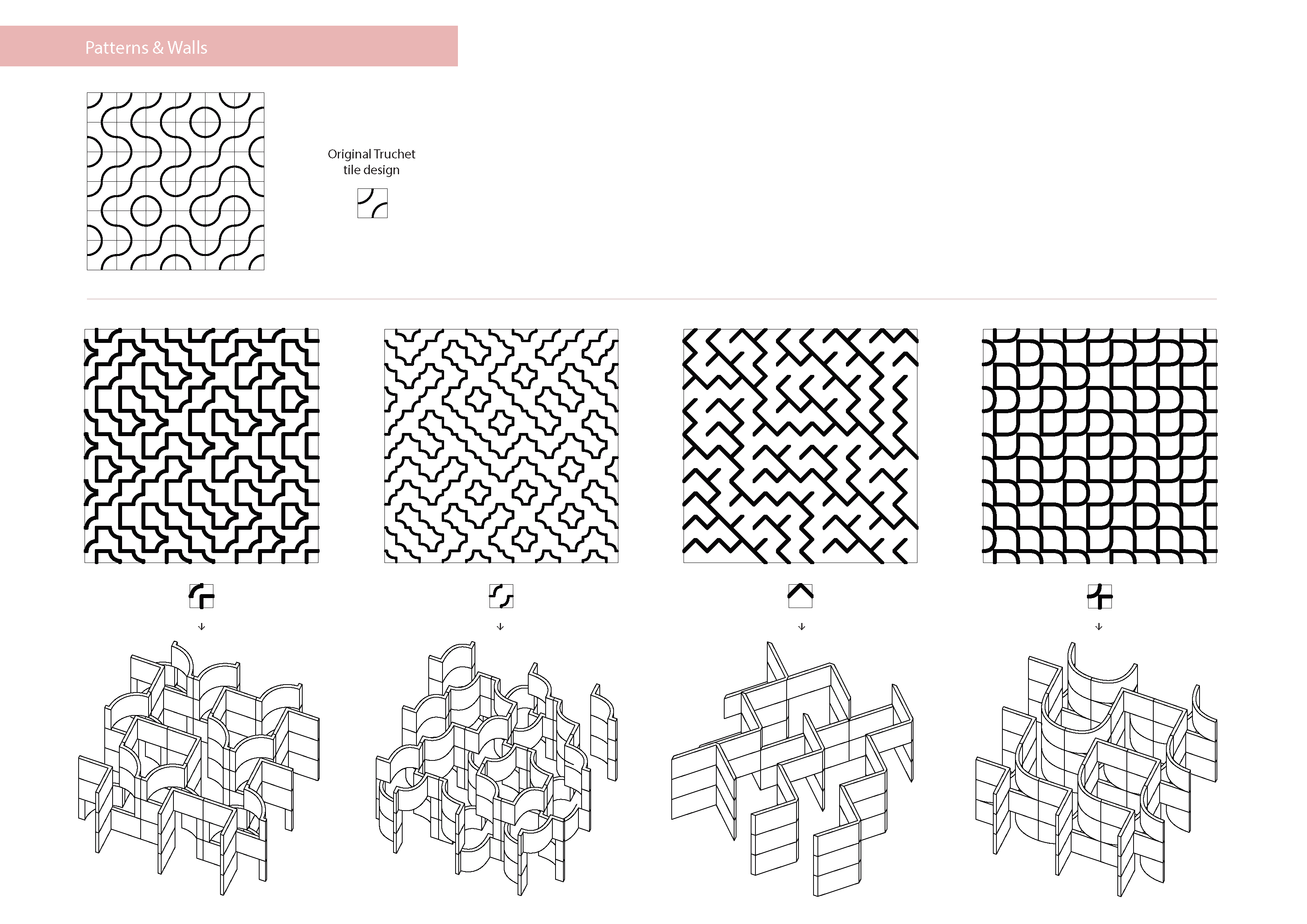
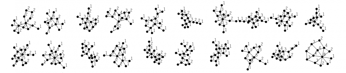
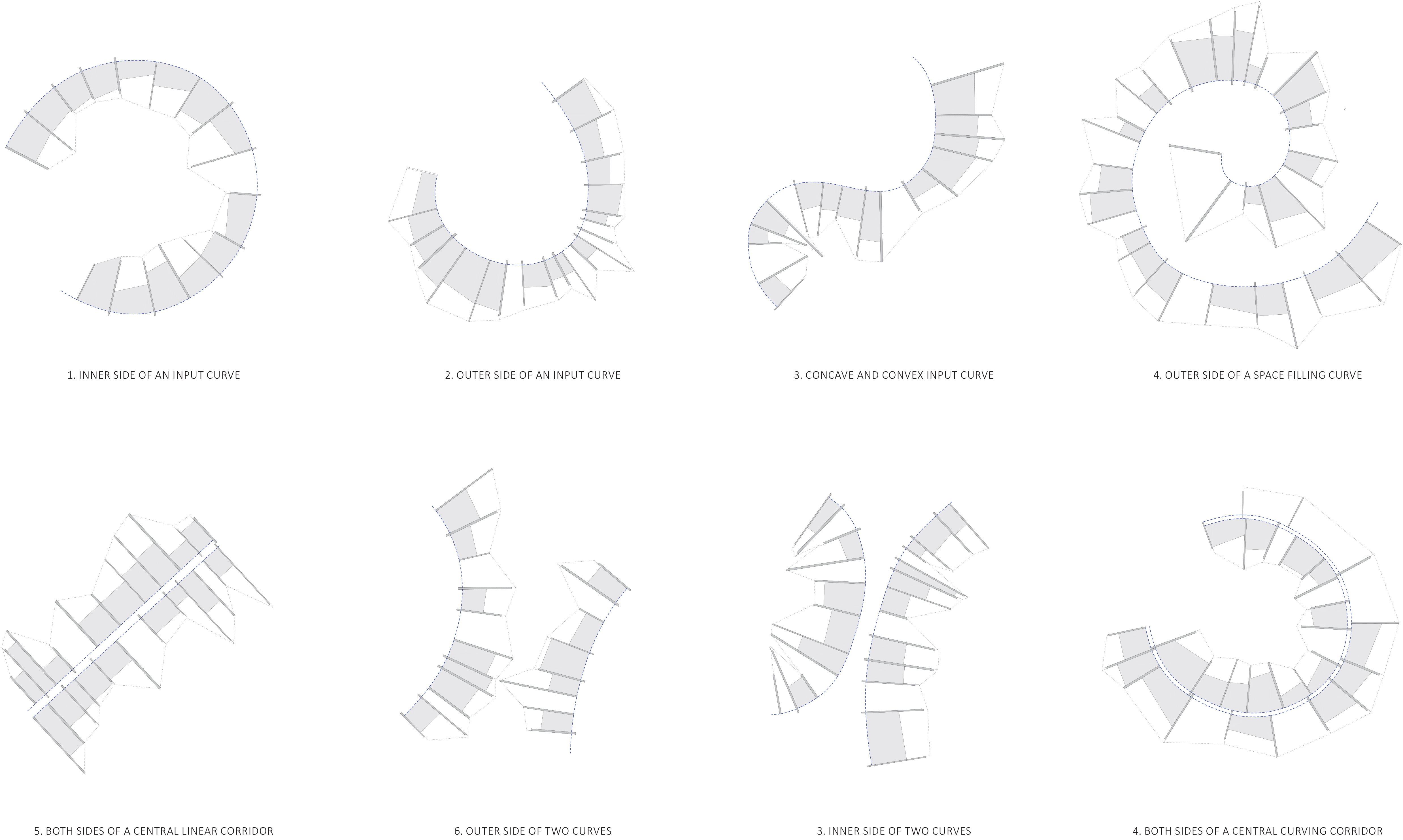
I then also explored how different input curves could create different spaces and variations by using the same script.

Final presentation.indd

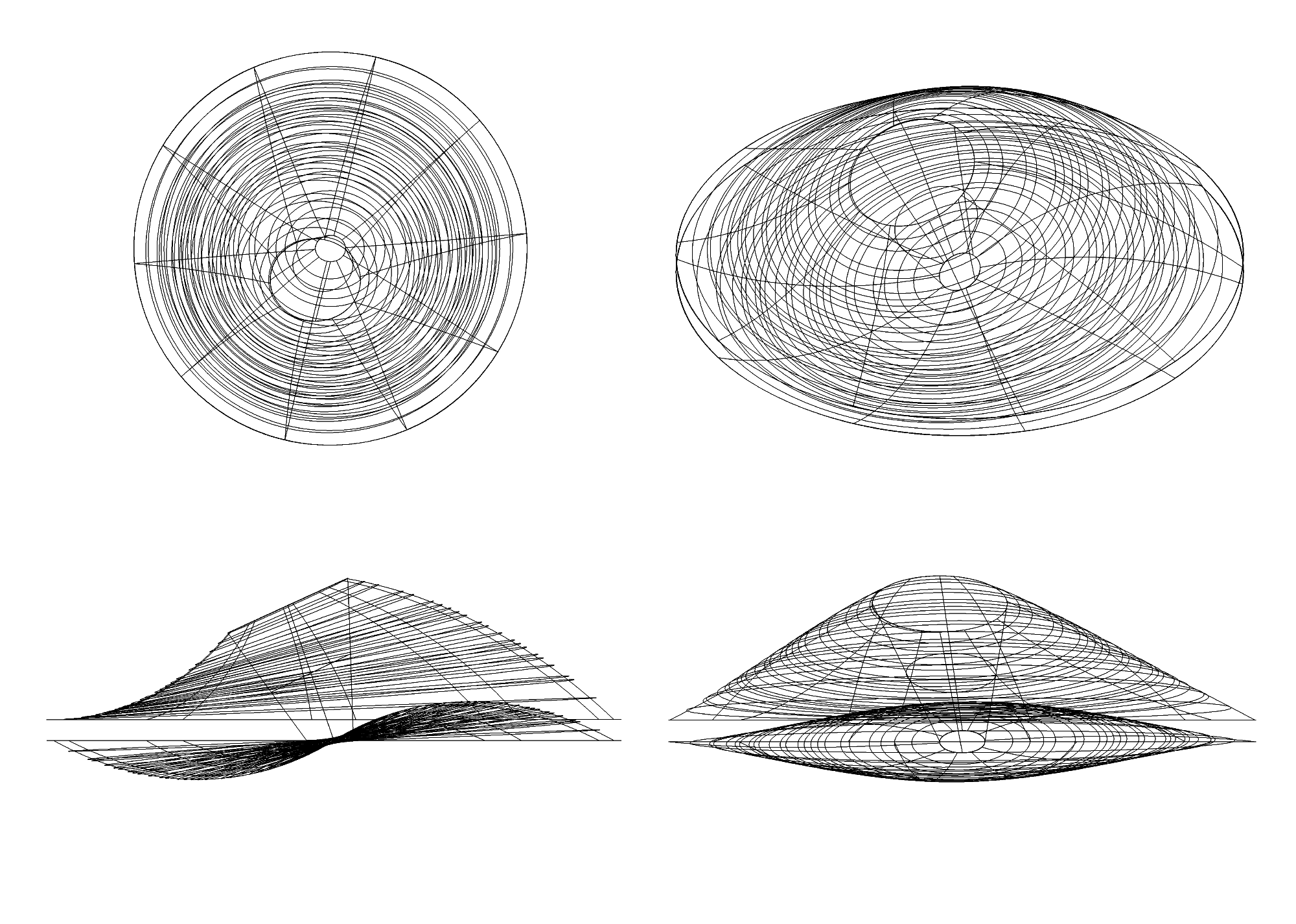
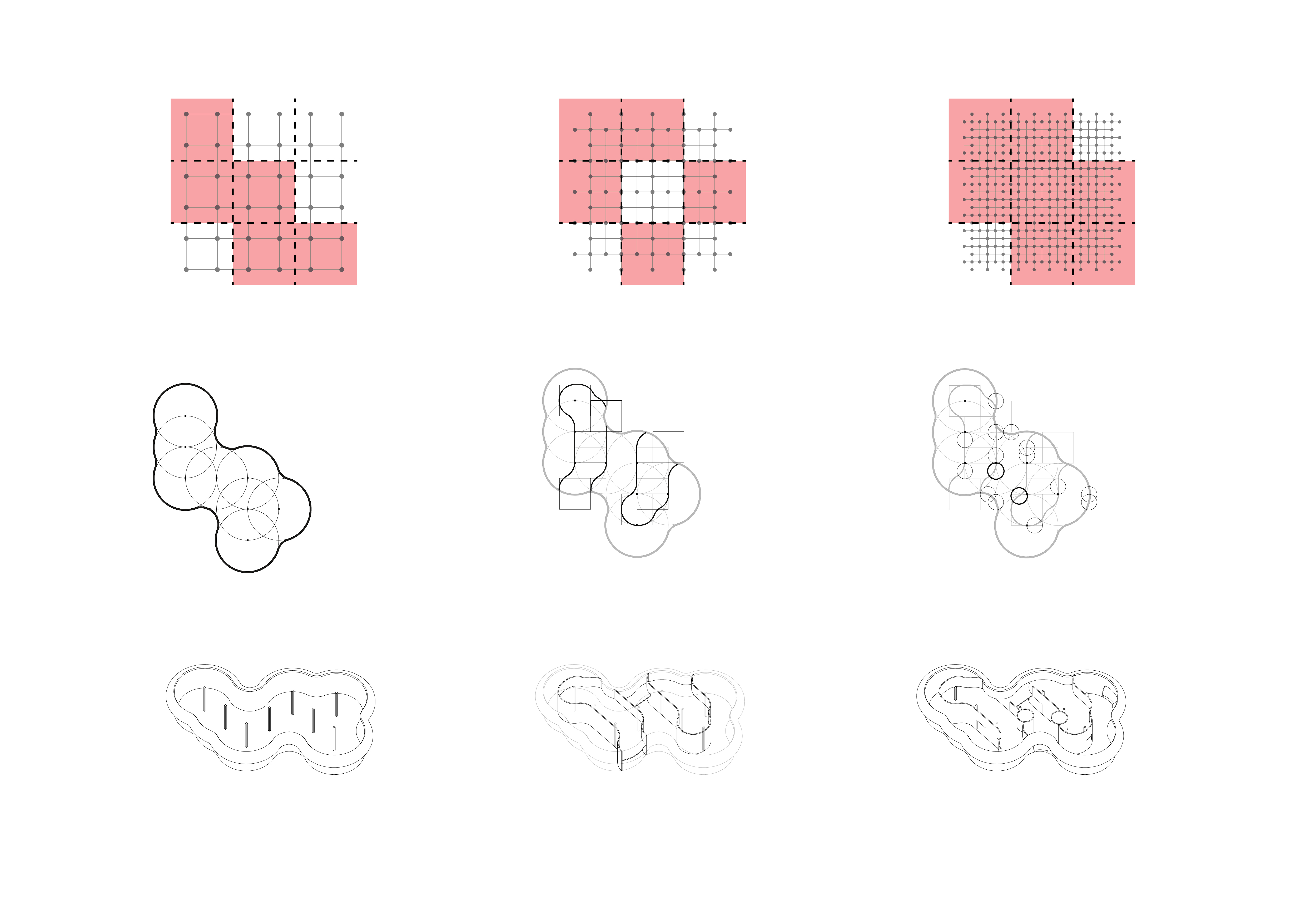
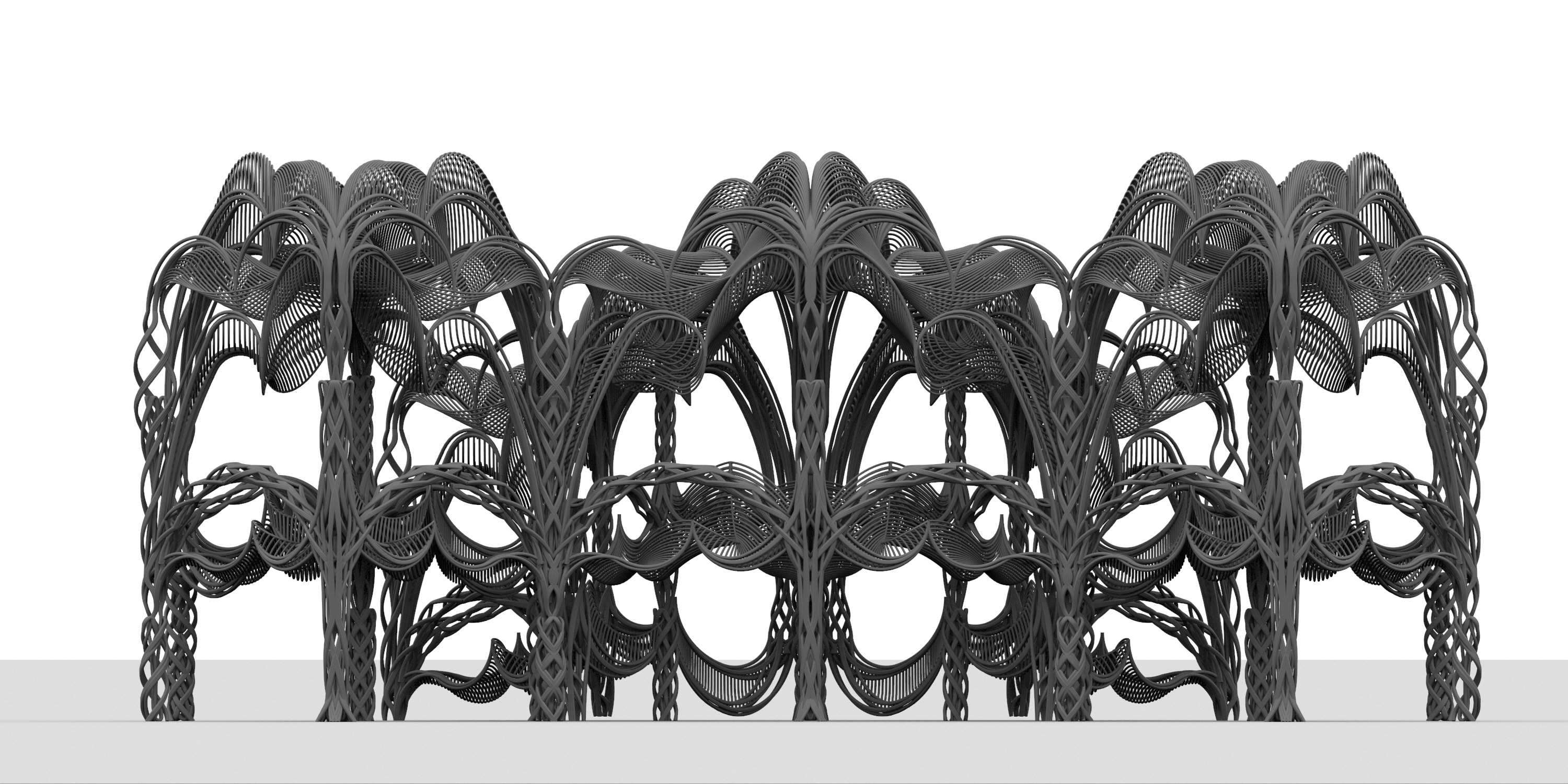
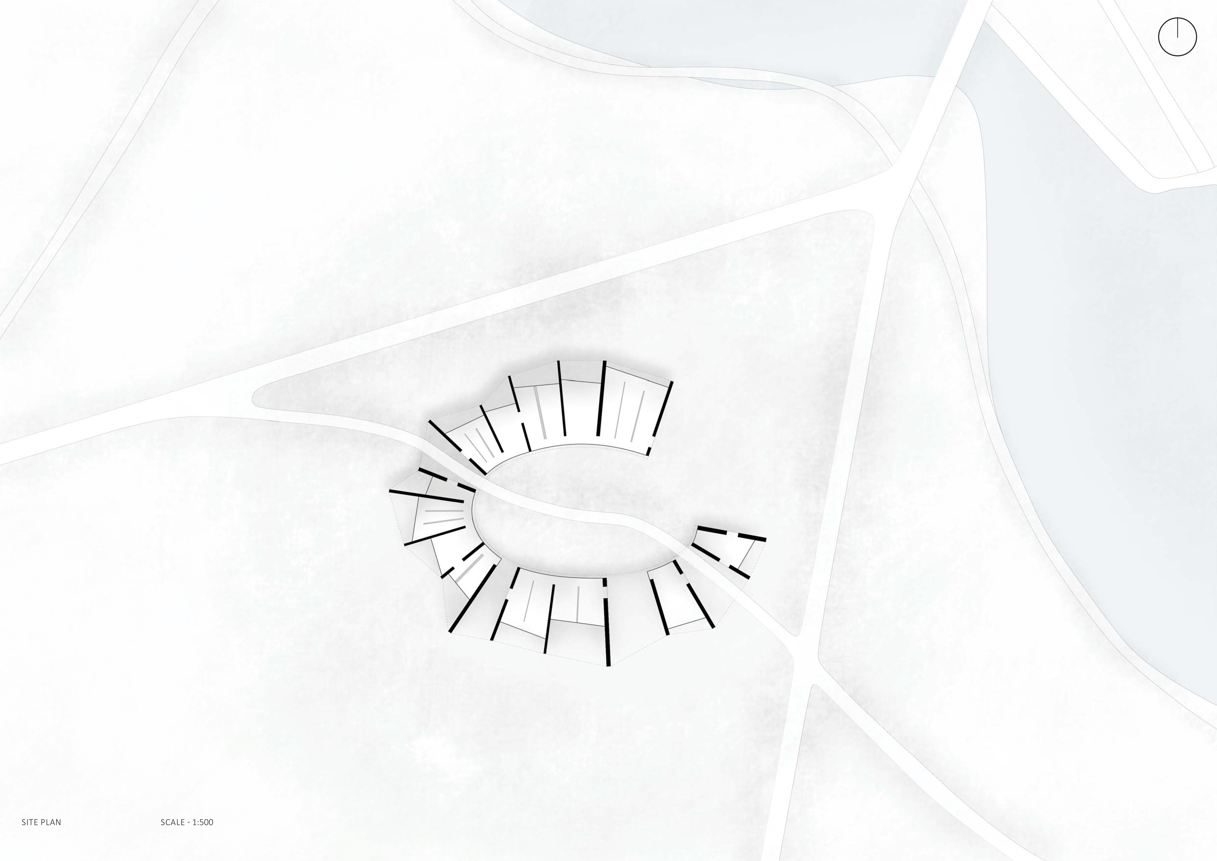
Below is an example of one of the many unique generations that can be produced on the exact same curve. If used on different input curves I could create even more unique variations.

Final presentation.indd

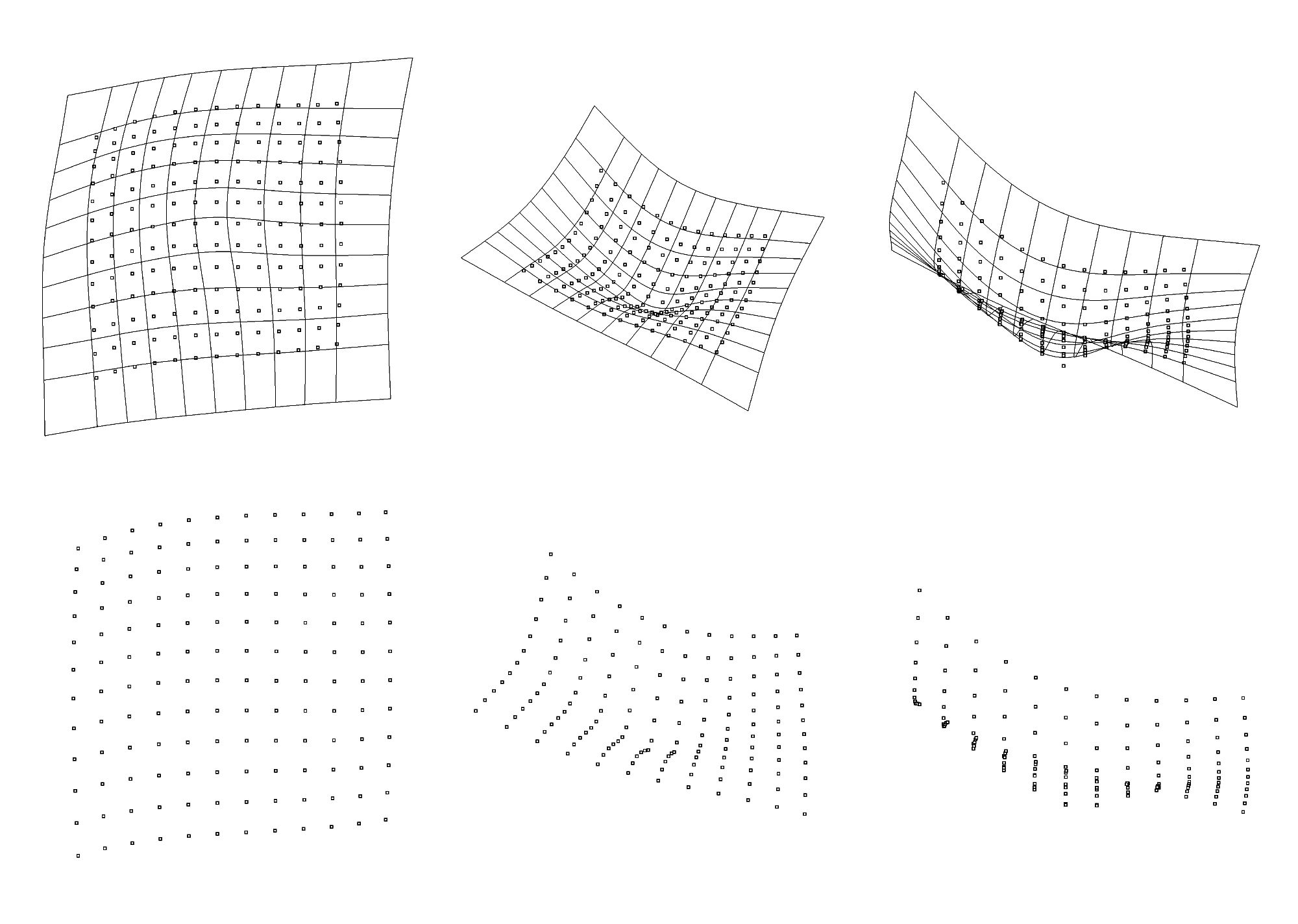
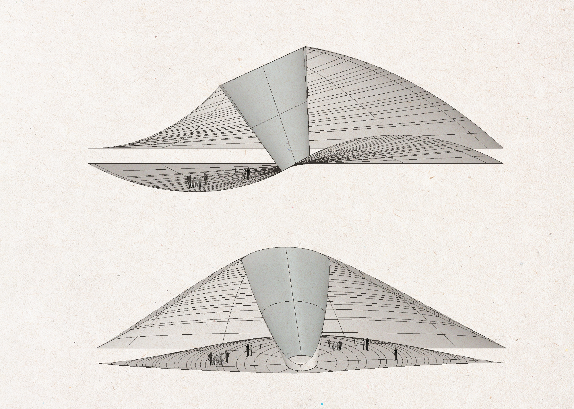
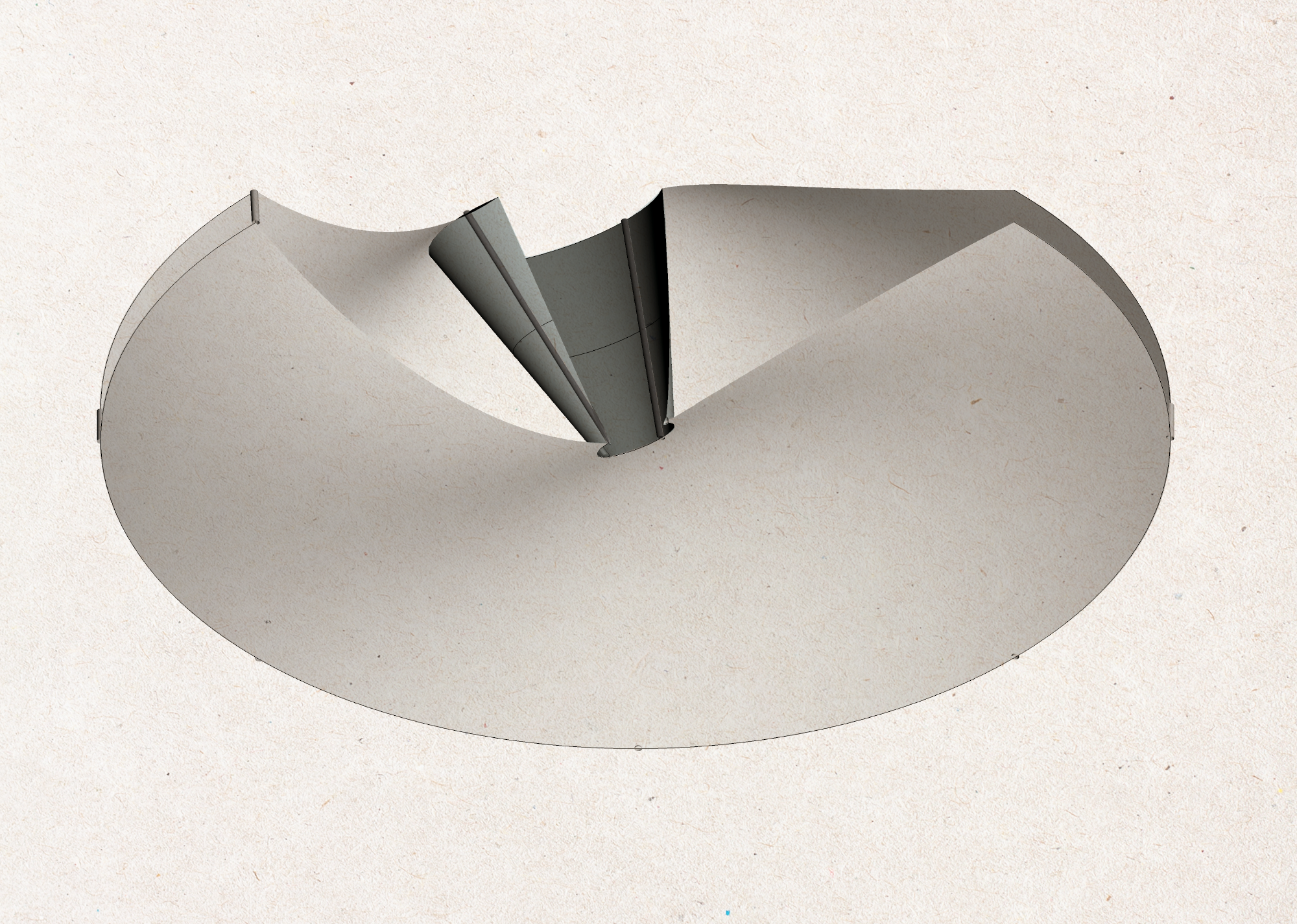
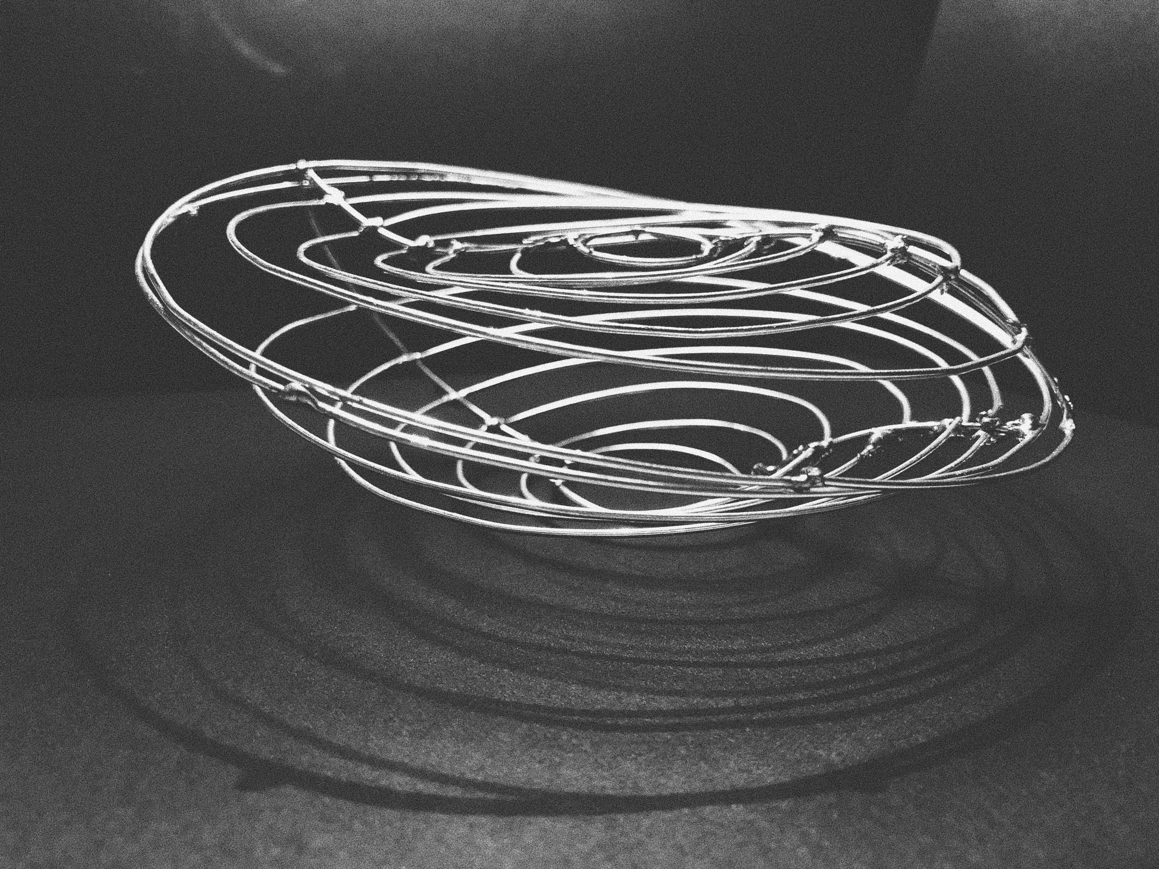
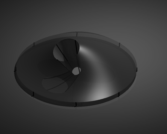
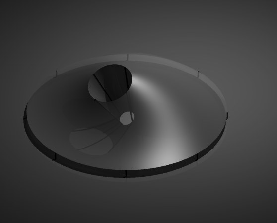
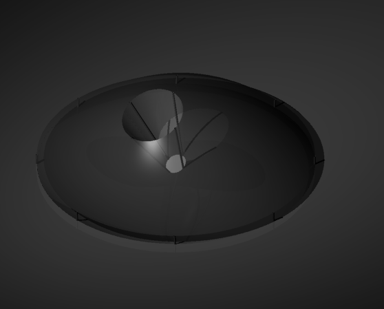
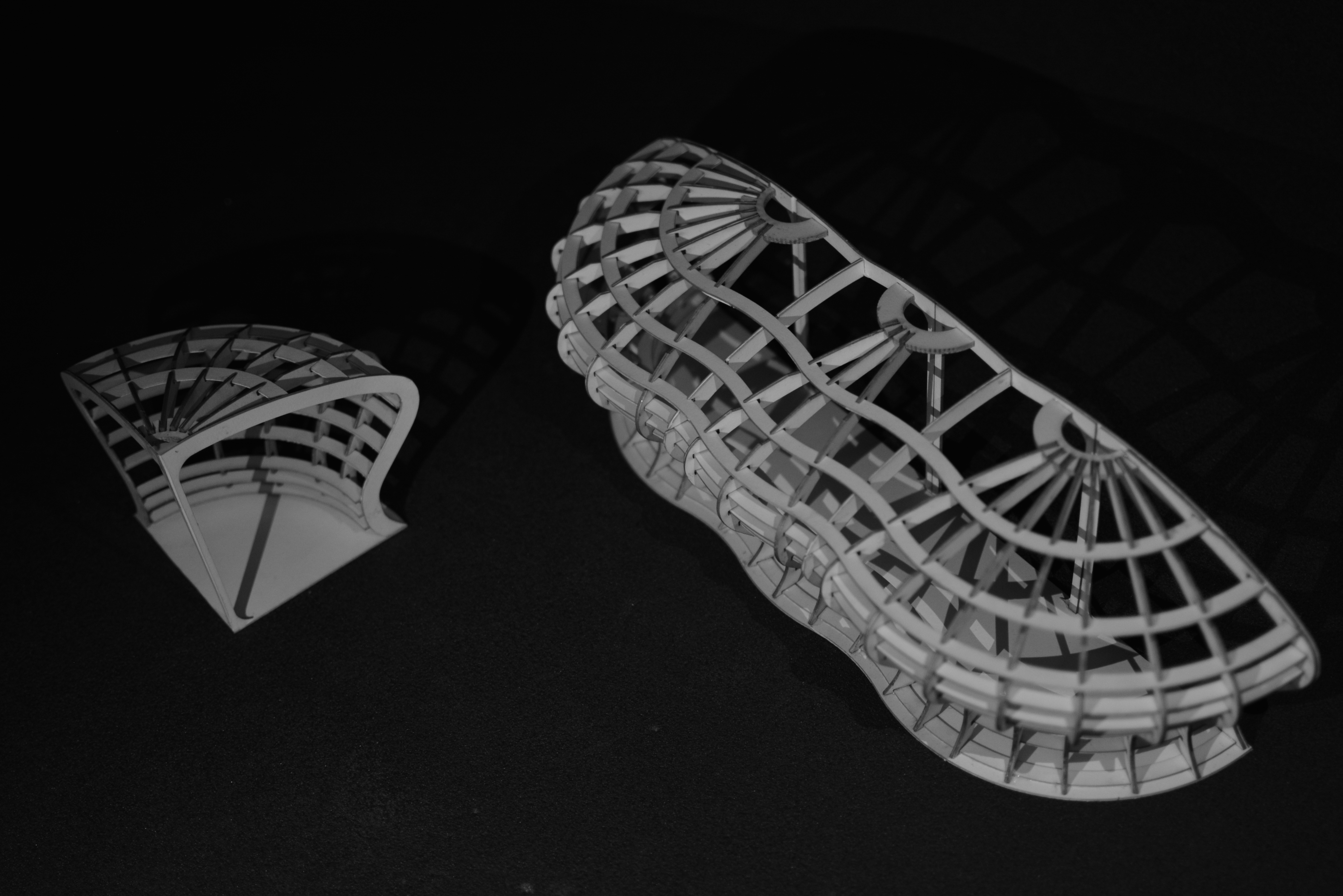
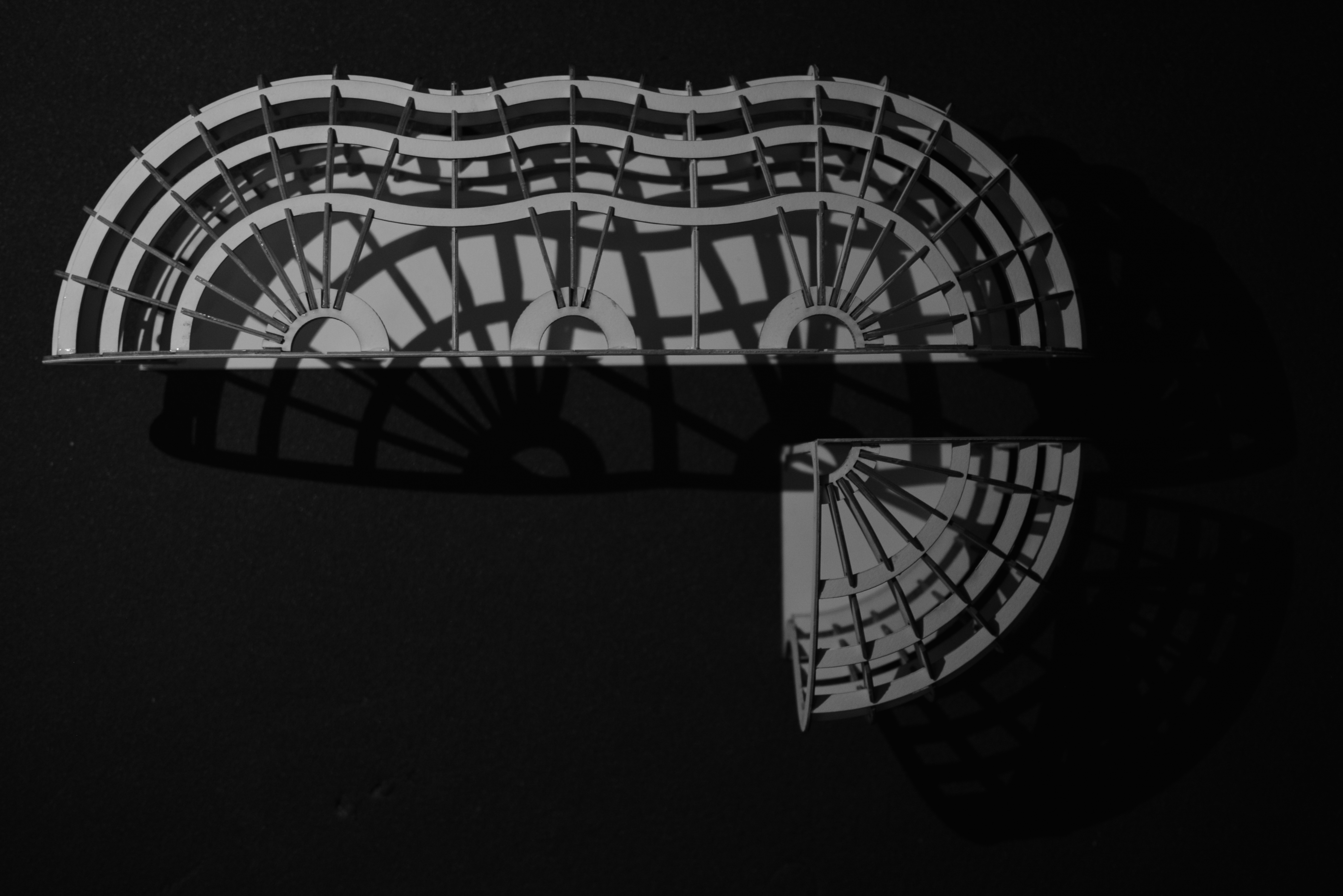
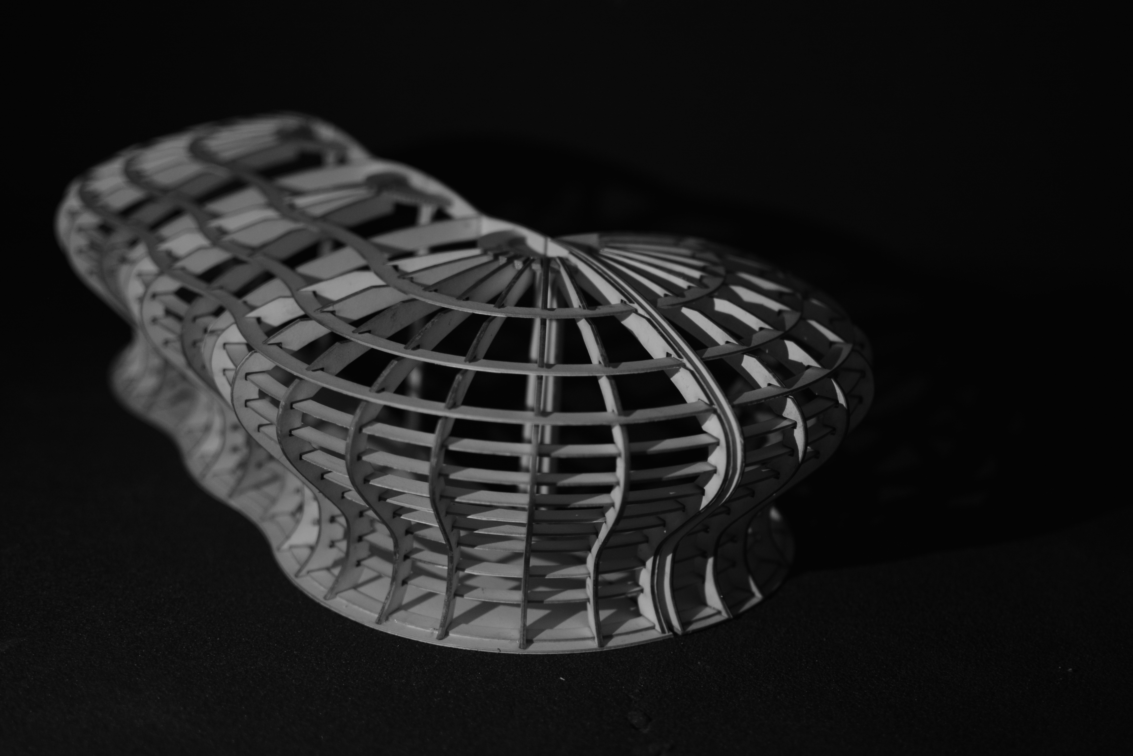
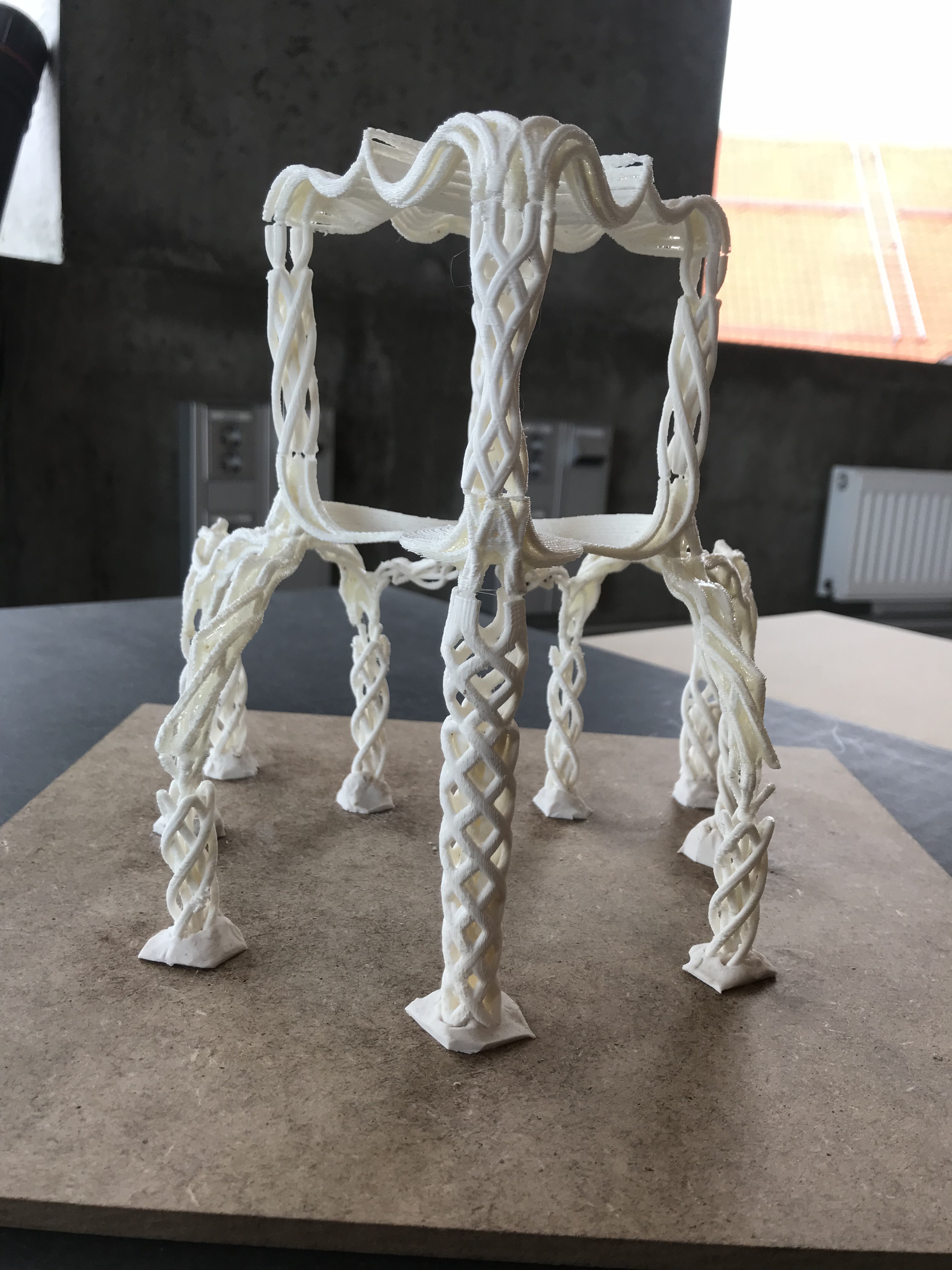
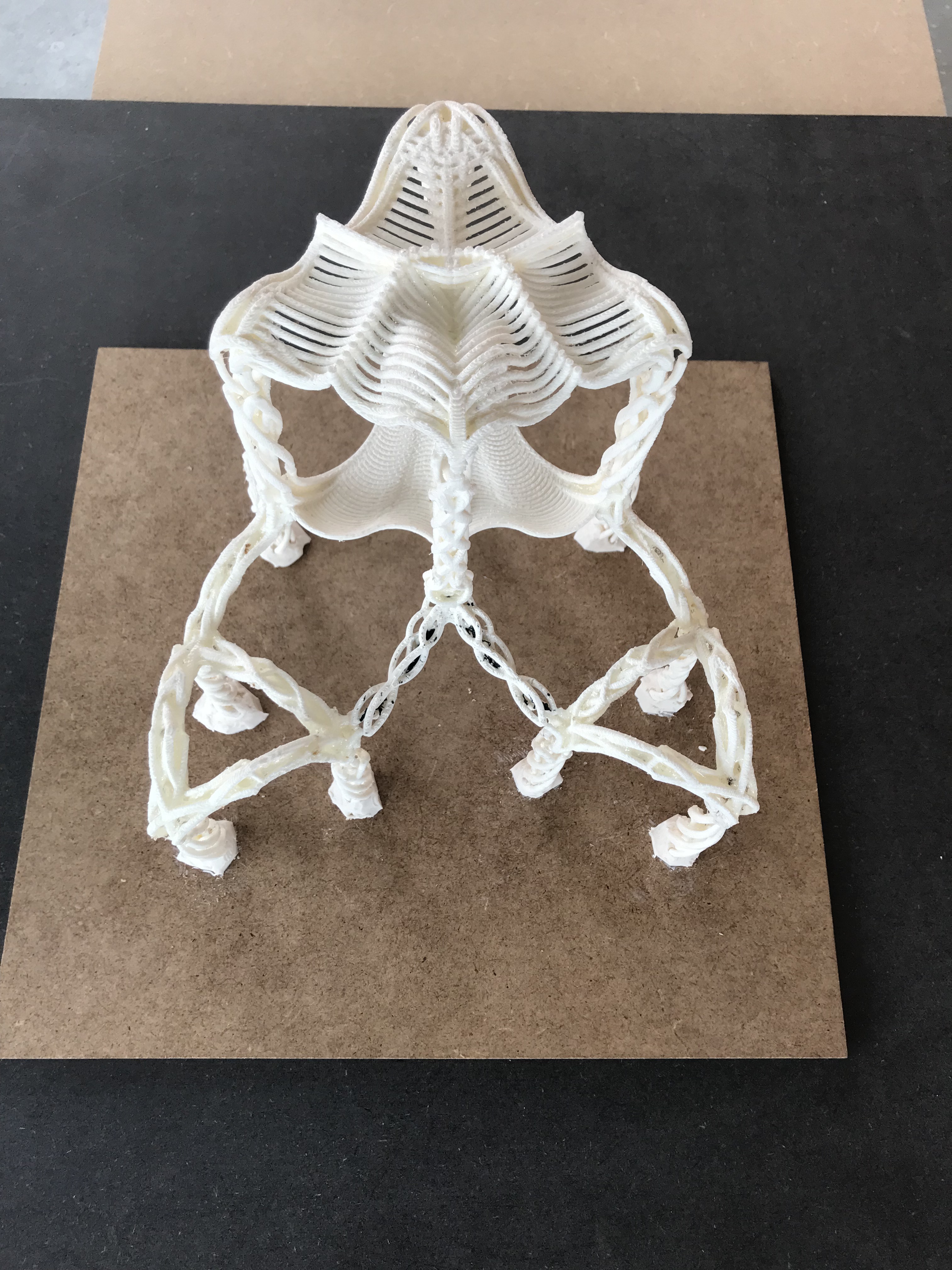
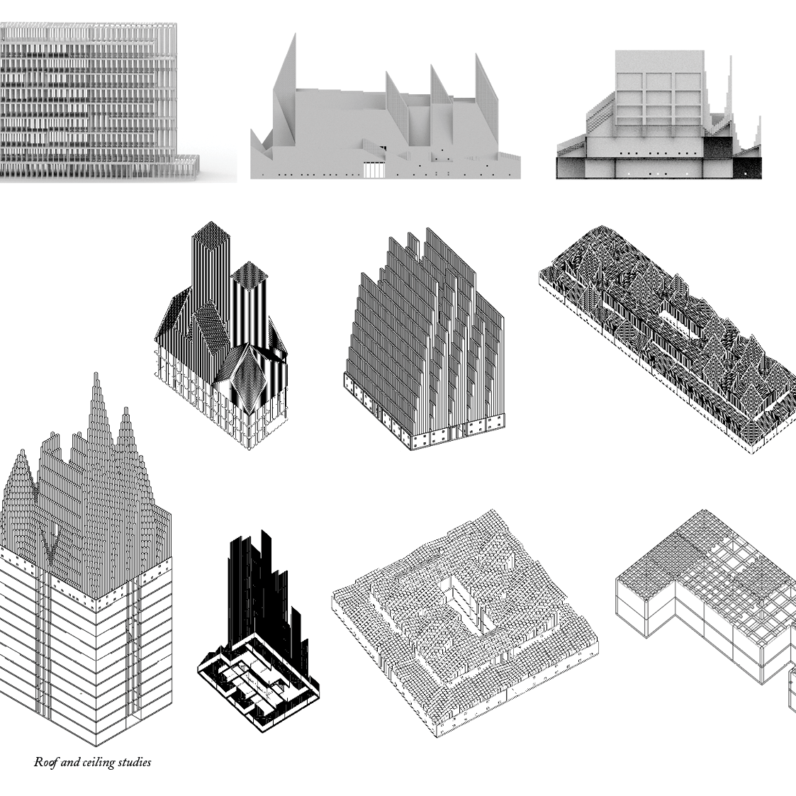
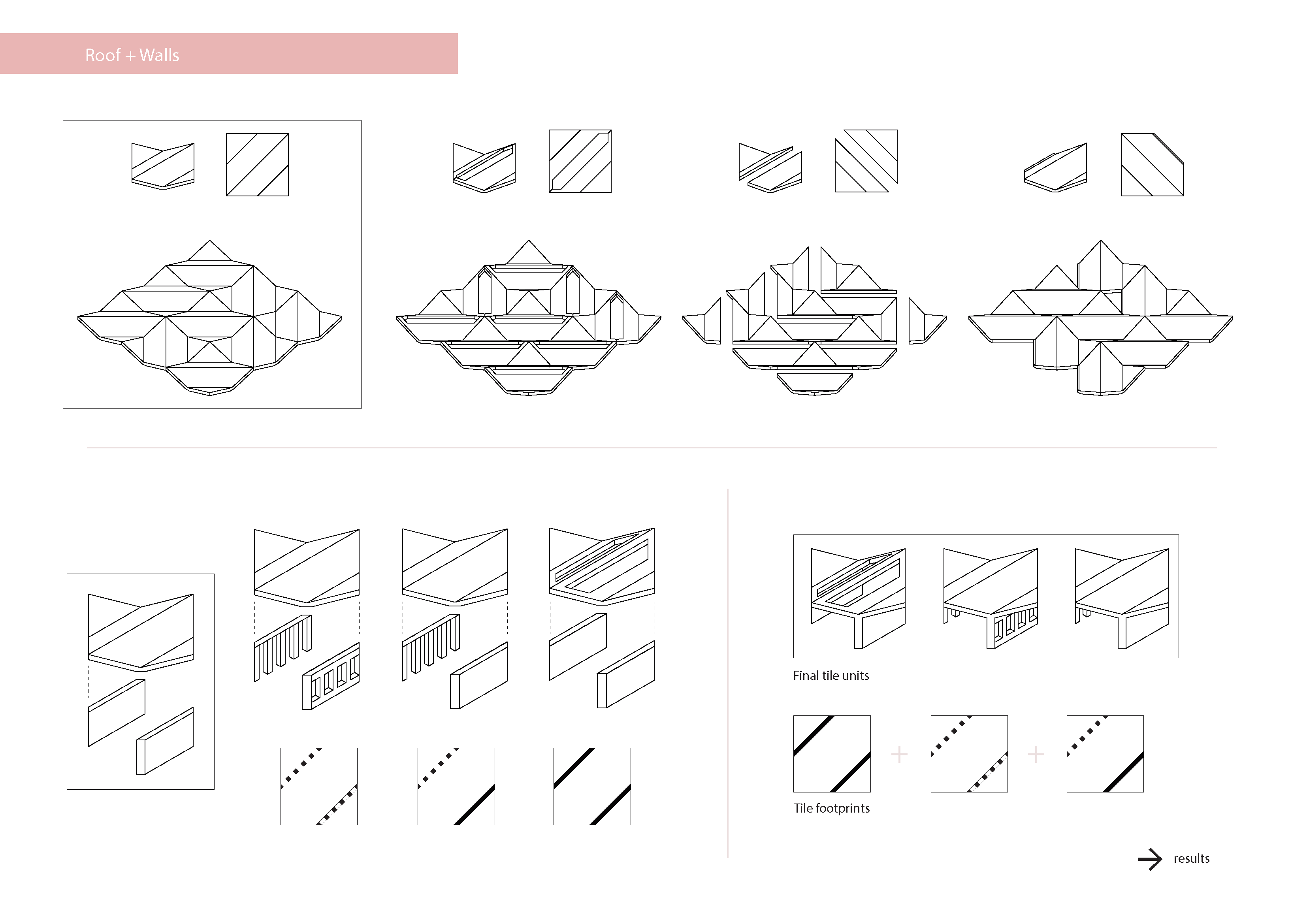
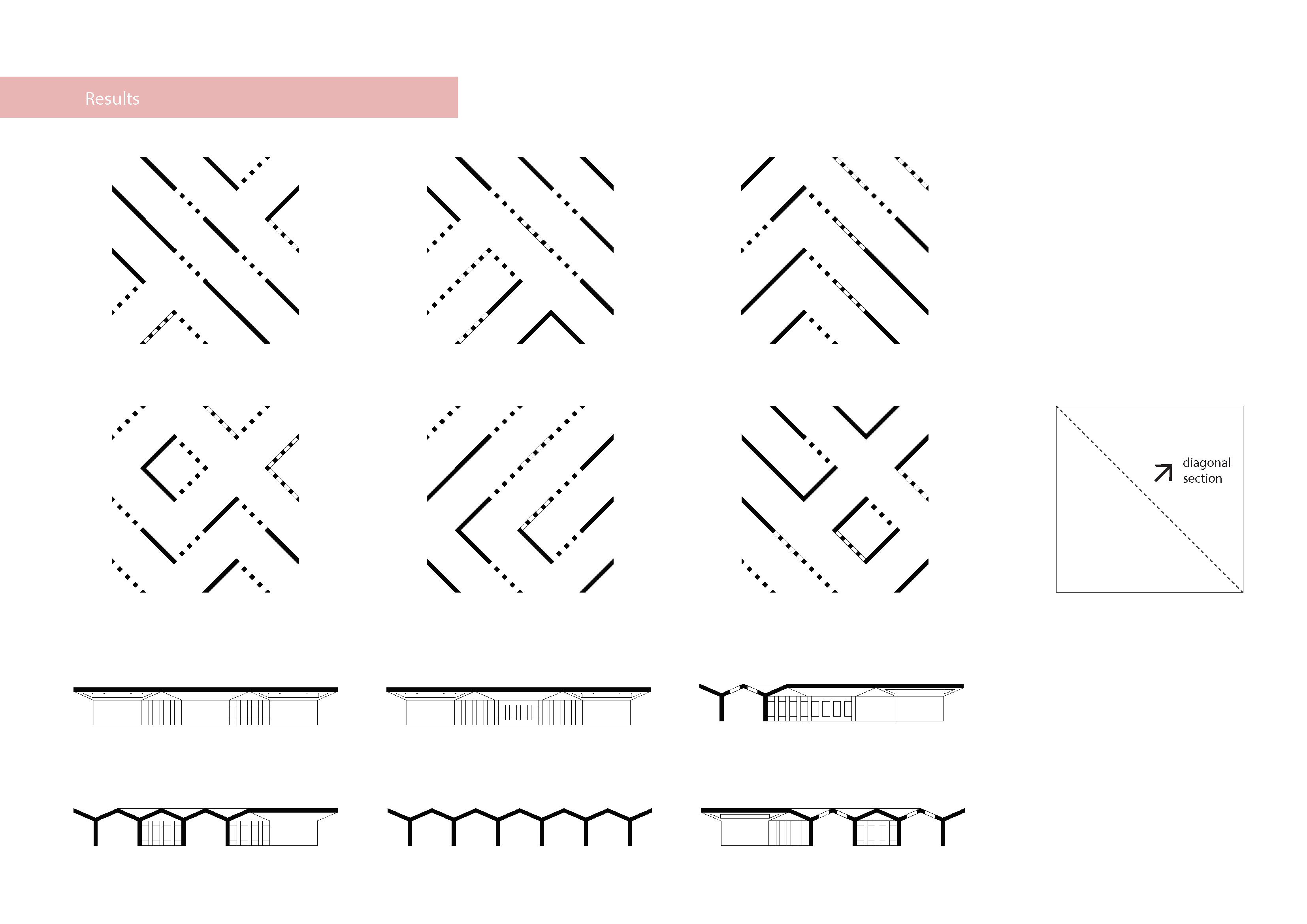
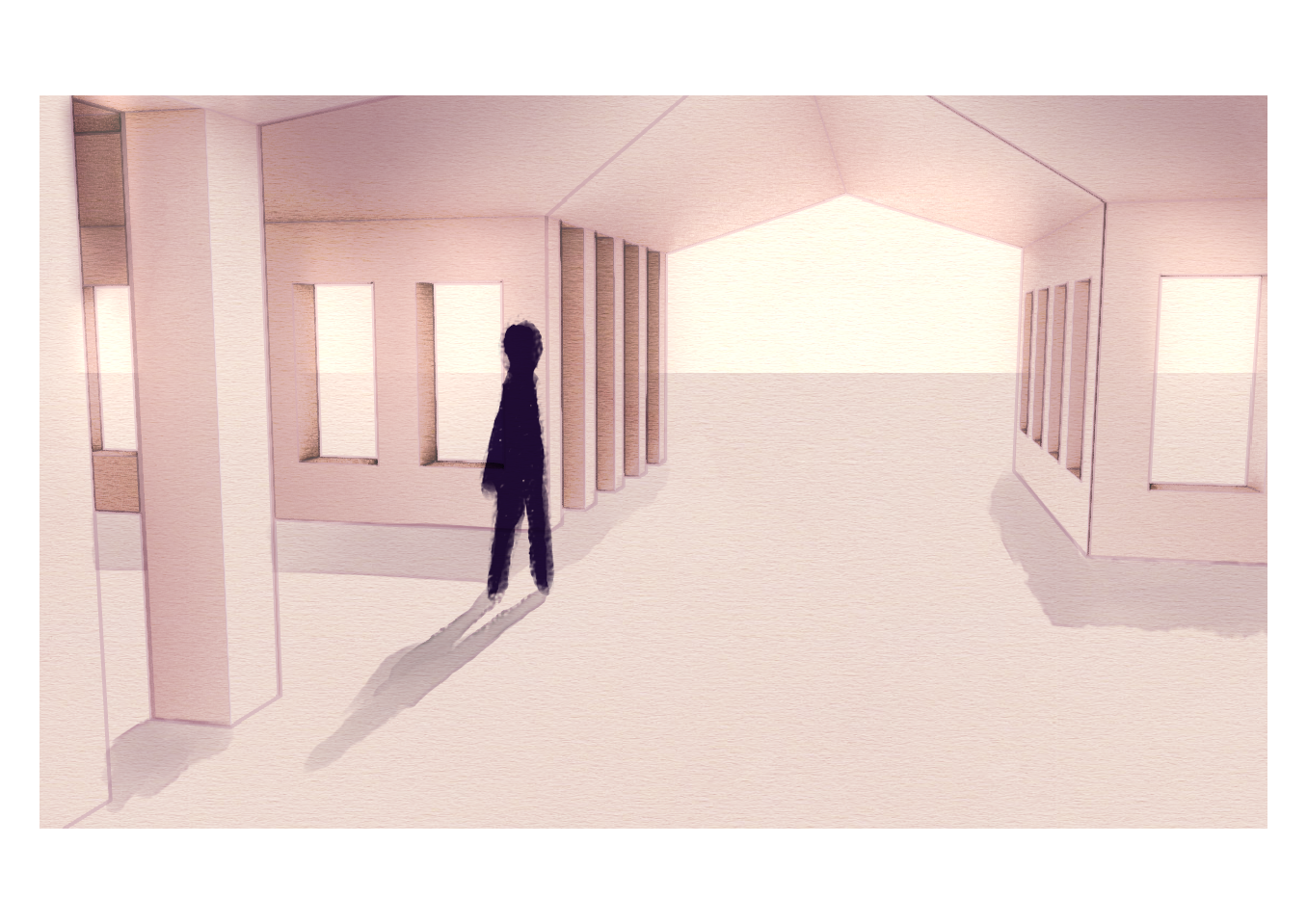
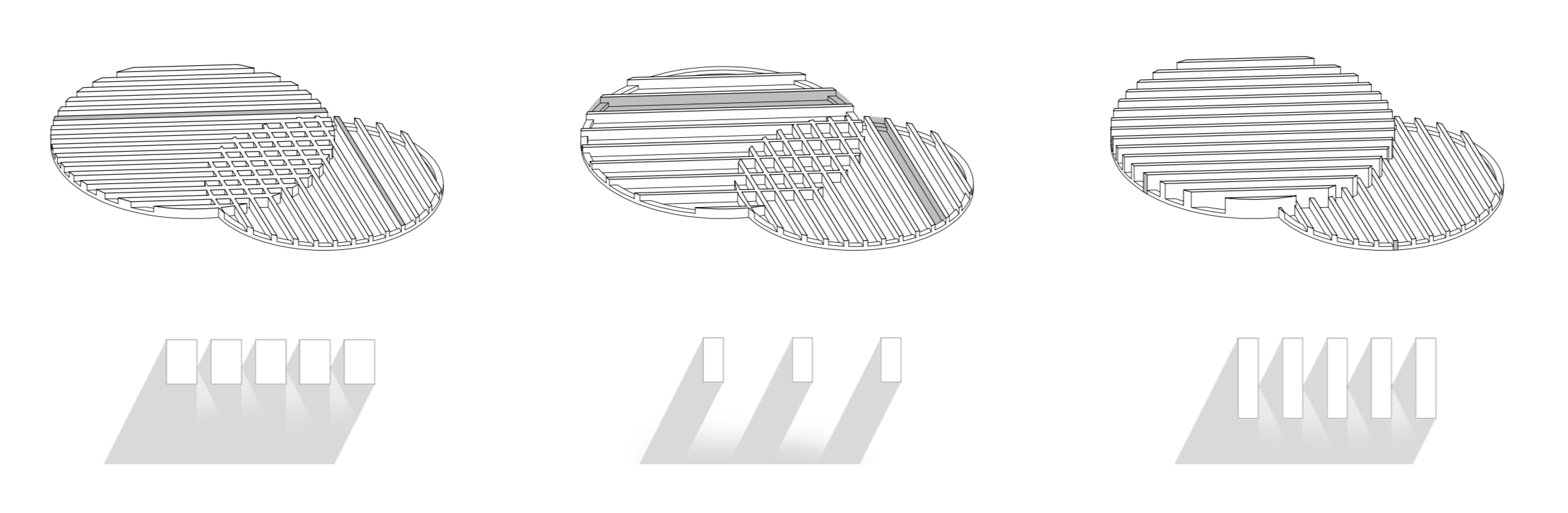
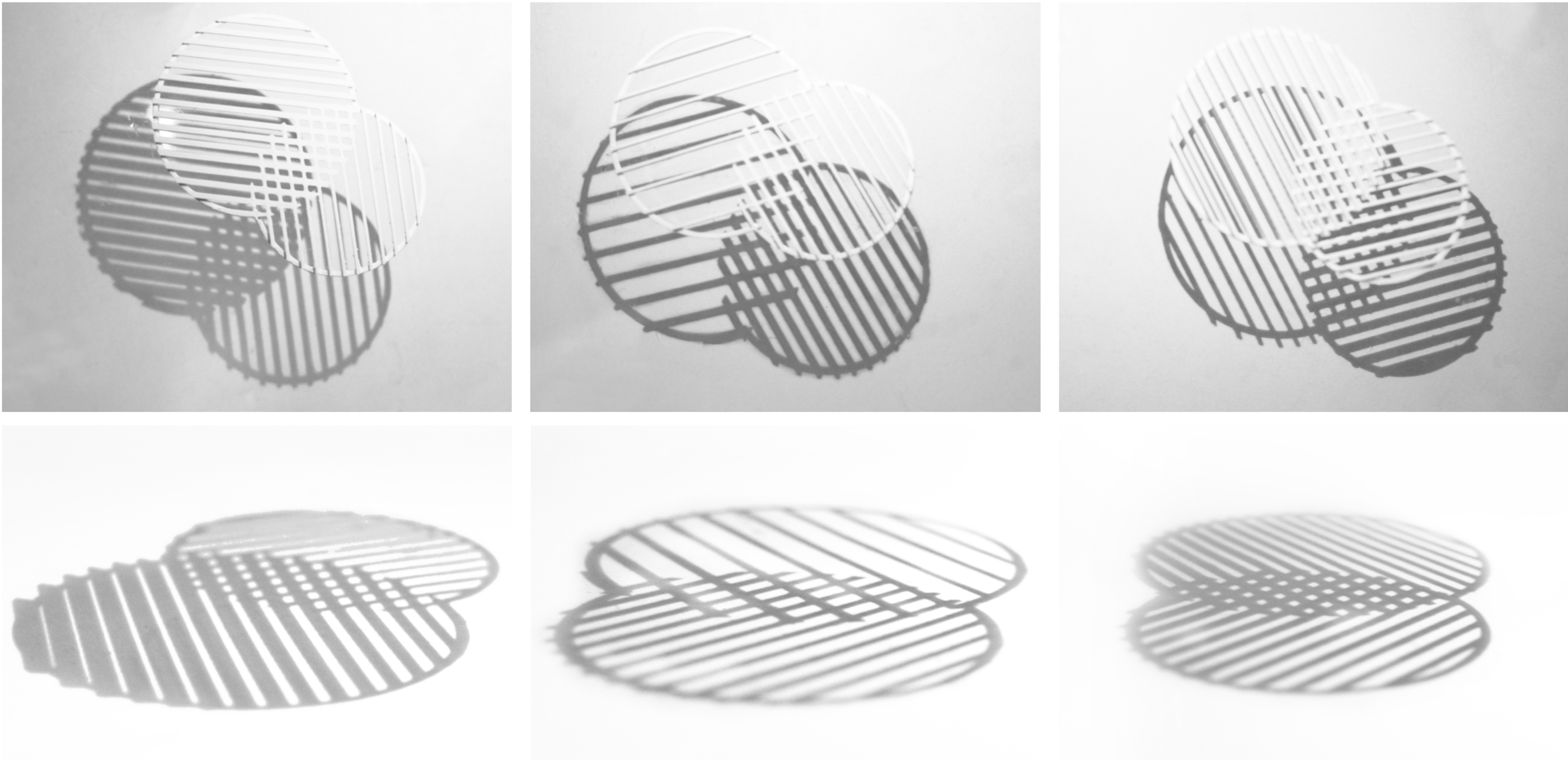
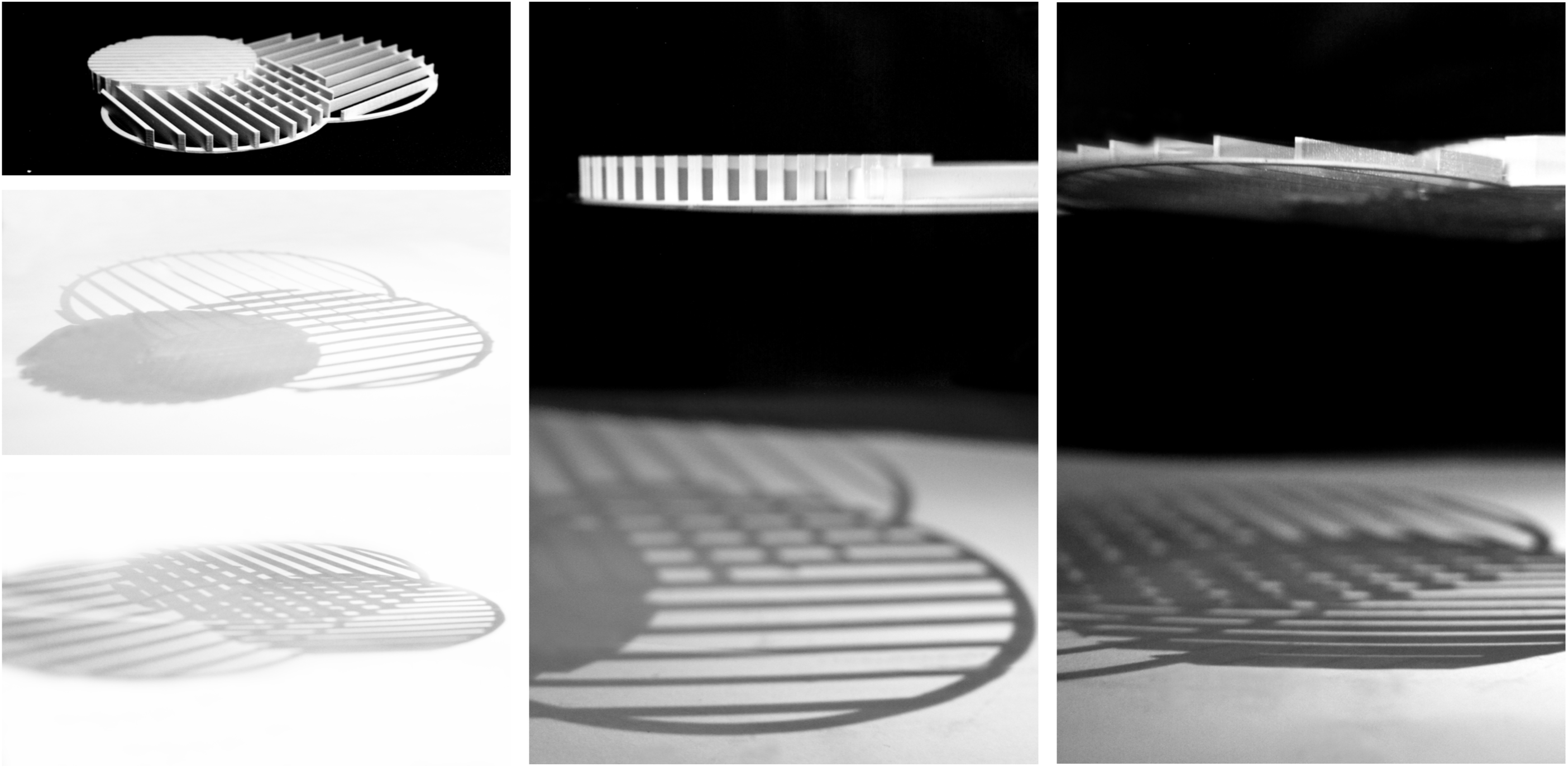
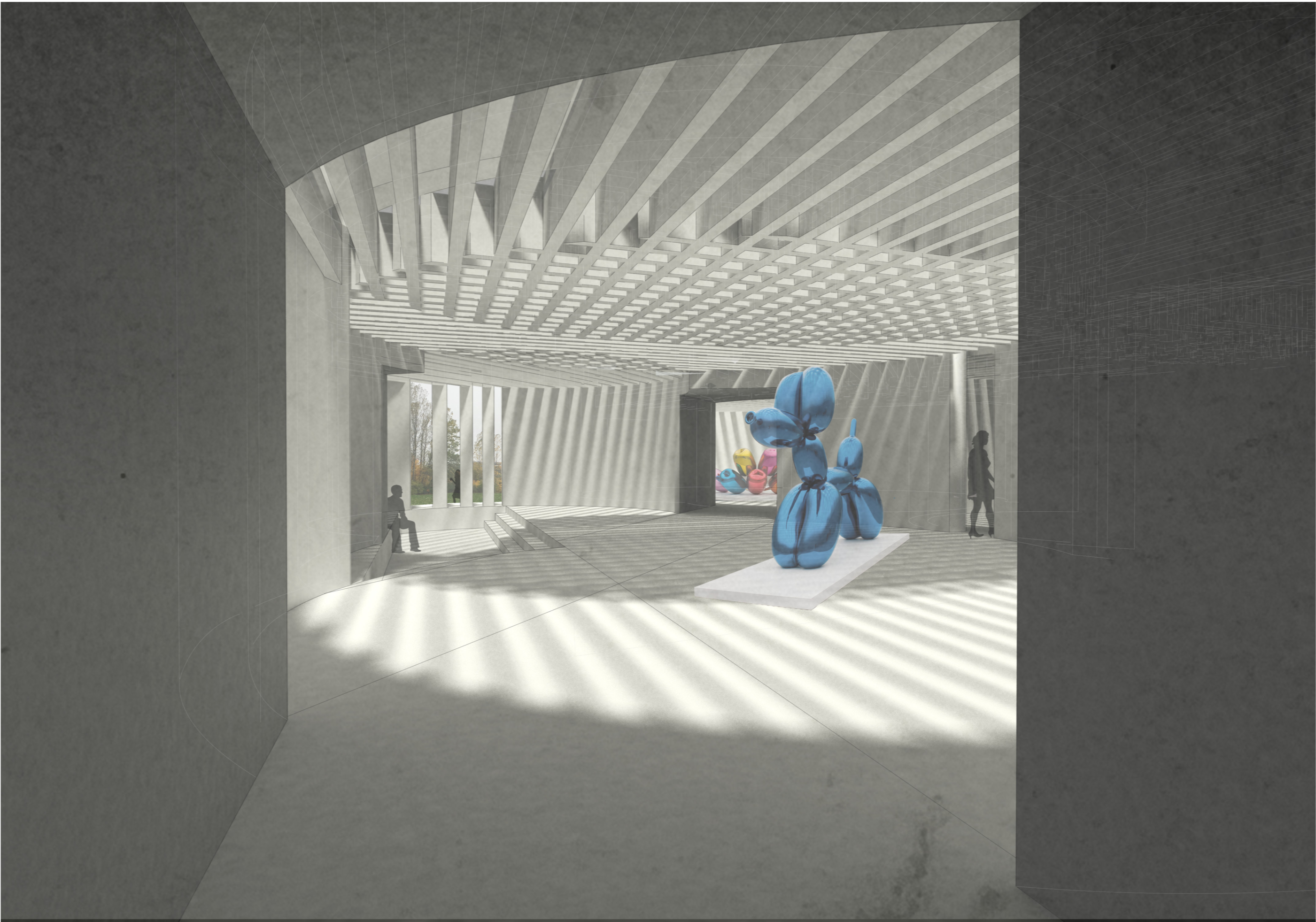
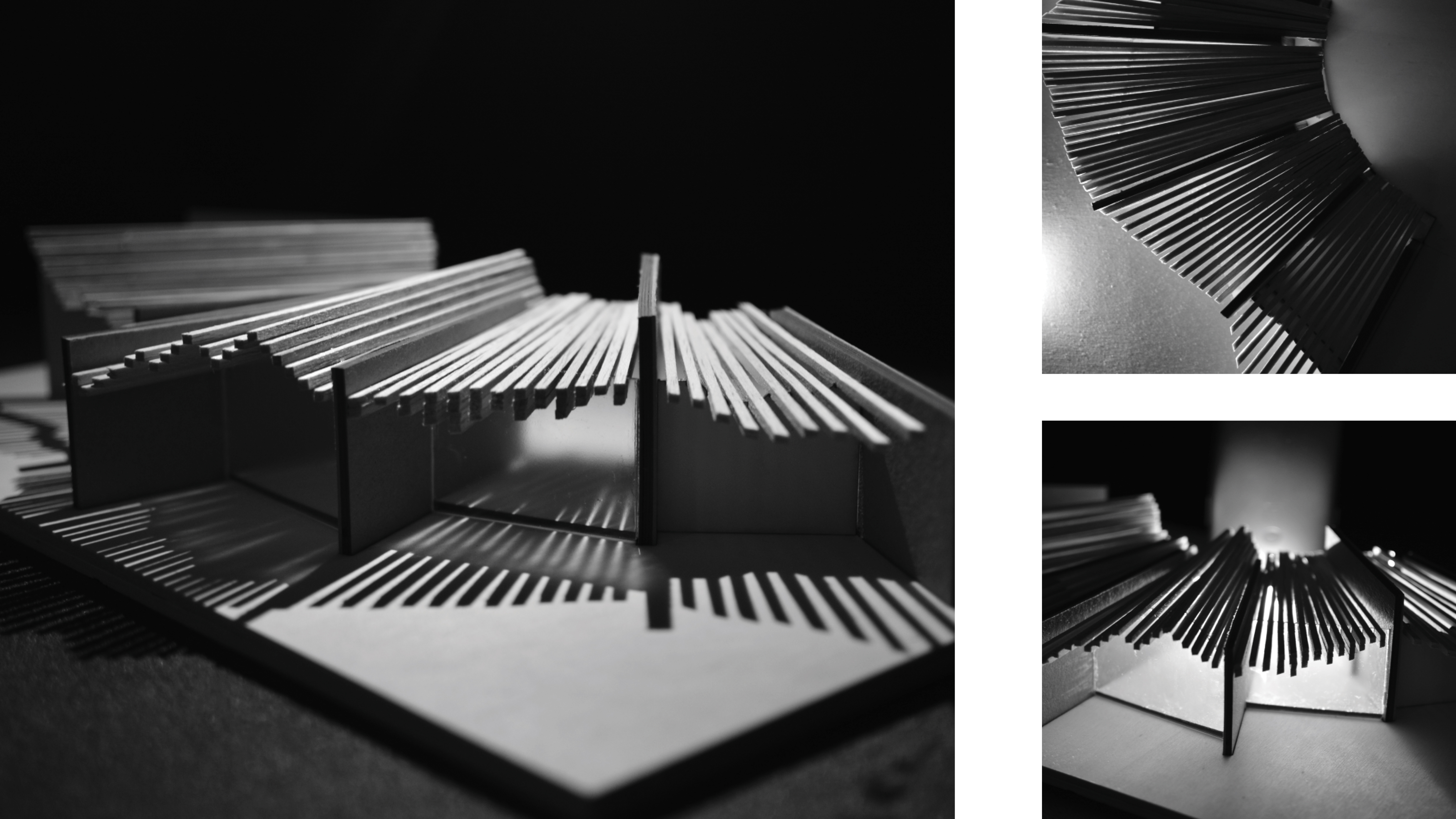
I started to look at the roof form in more detail by considering how it could vary in different ways to affect the environment and experience of the space below. I would then use this to dictate what spaces could be used for. I considered how the spacing and arrangements could be altered to let through different amounts of light, or no light if you want to project video installations. They could even be used as acoustic buffers in tall spaces. Whilst I was exploring the variations of roof form and the transparency of the walls to shut off and expose views, I still wanted the roof form to appear as one cohesive system.

Final presentation.indd

Final presentation.indd


Inhabiting the curve.

The final presentation for project_01 brought about the exploration of light and  materiality through the medium of models. Working through sketches, I began exploring the roof grid and it’s correlation to the curved plan with an experimental approach to  how their relationship is articulated in the physical form.

This slideshow requires JavaScript.

I worked through three card models using the laser cutter to achieve the curvatures of the dragon code, investigating the materiality of the curves, the spacing and placement of the roof.

The flow of movement through the building was a direct response to the location on site. Using the pond as a feature and arrival point, the Konsthall starts as a bench into a curved wall that sinks down into the ground and leads you back up into the waterfront.

Site
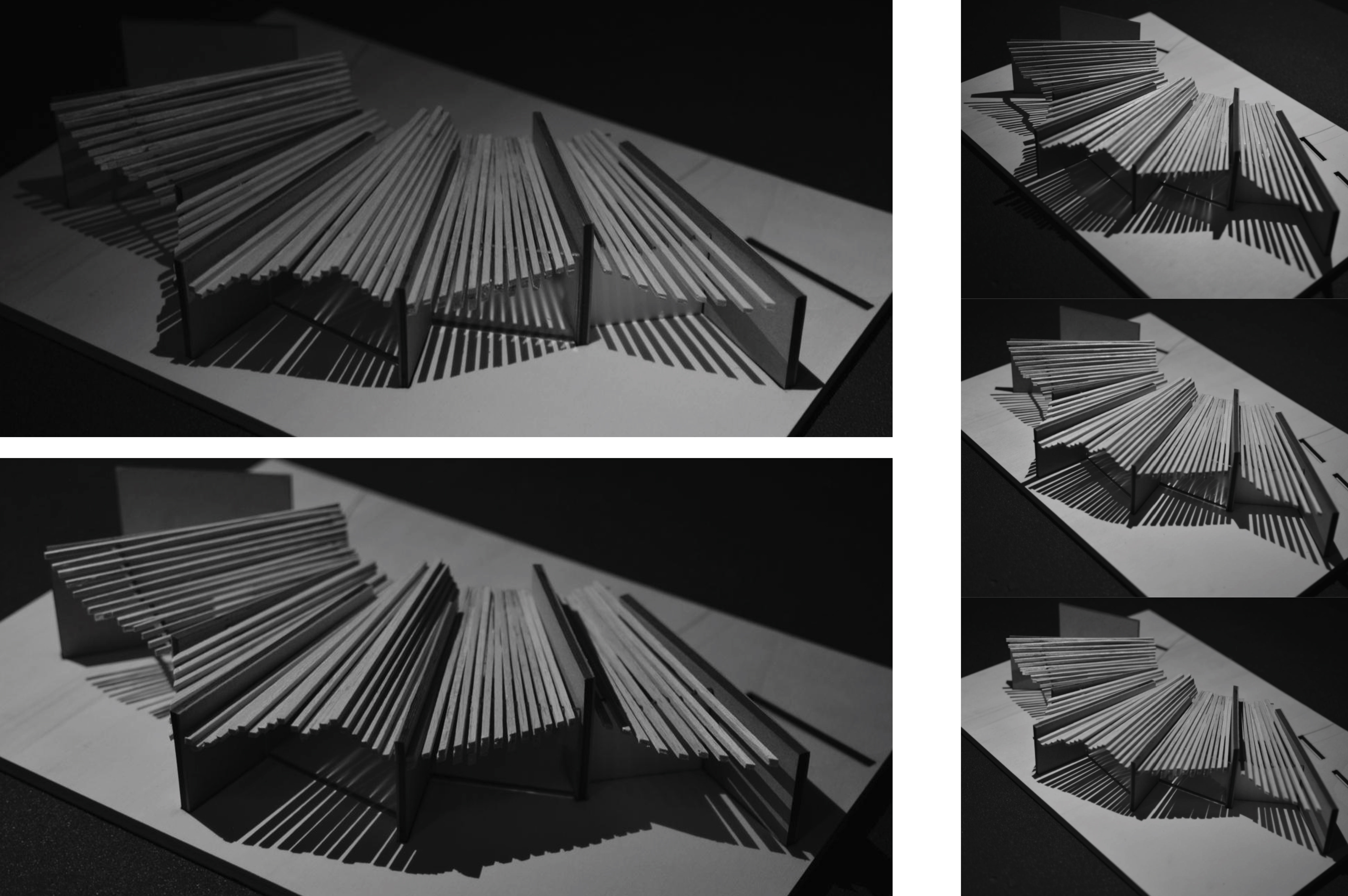
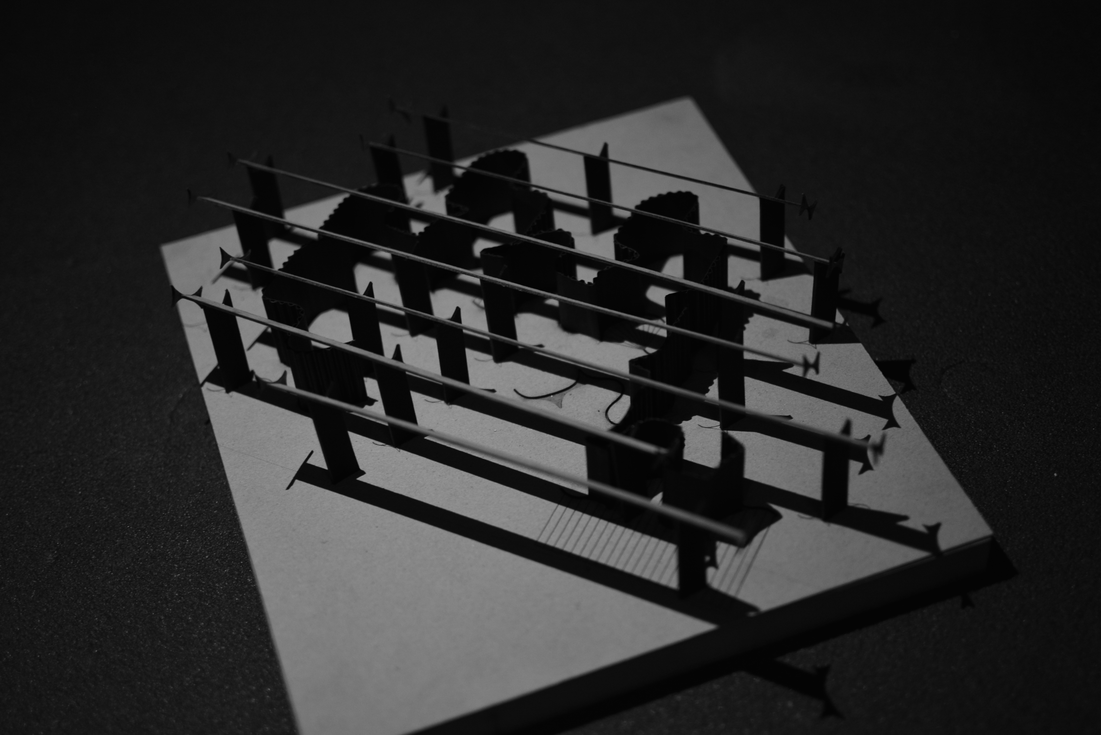
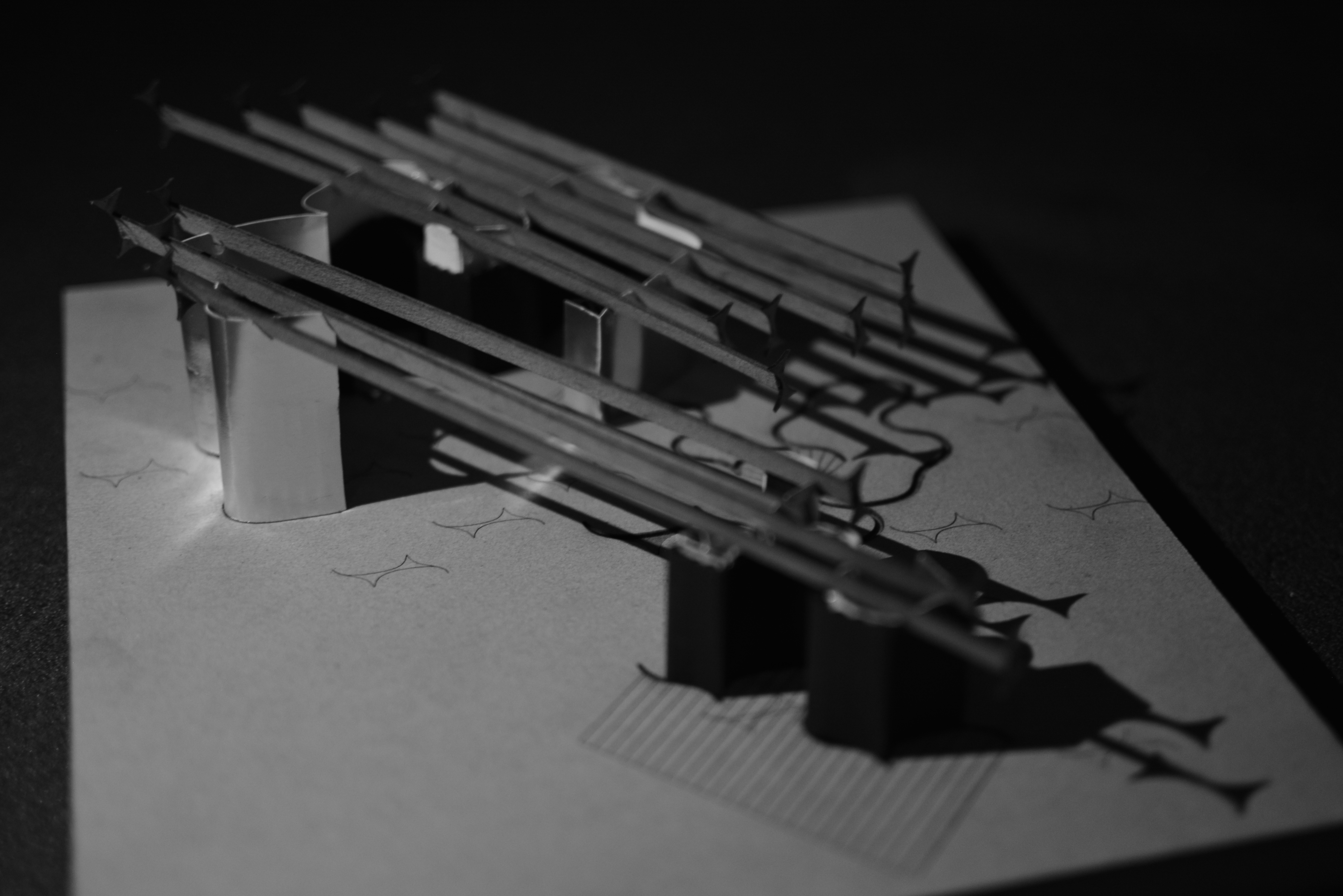
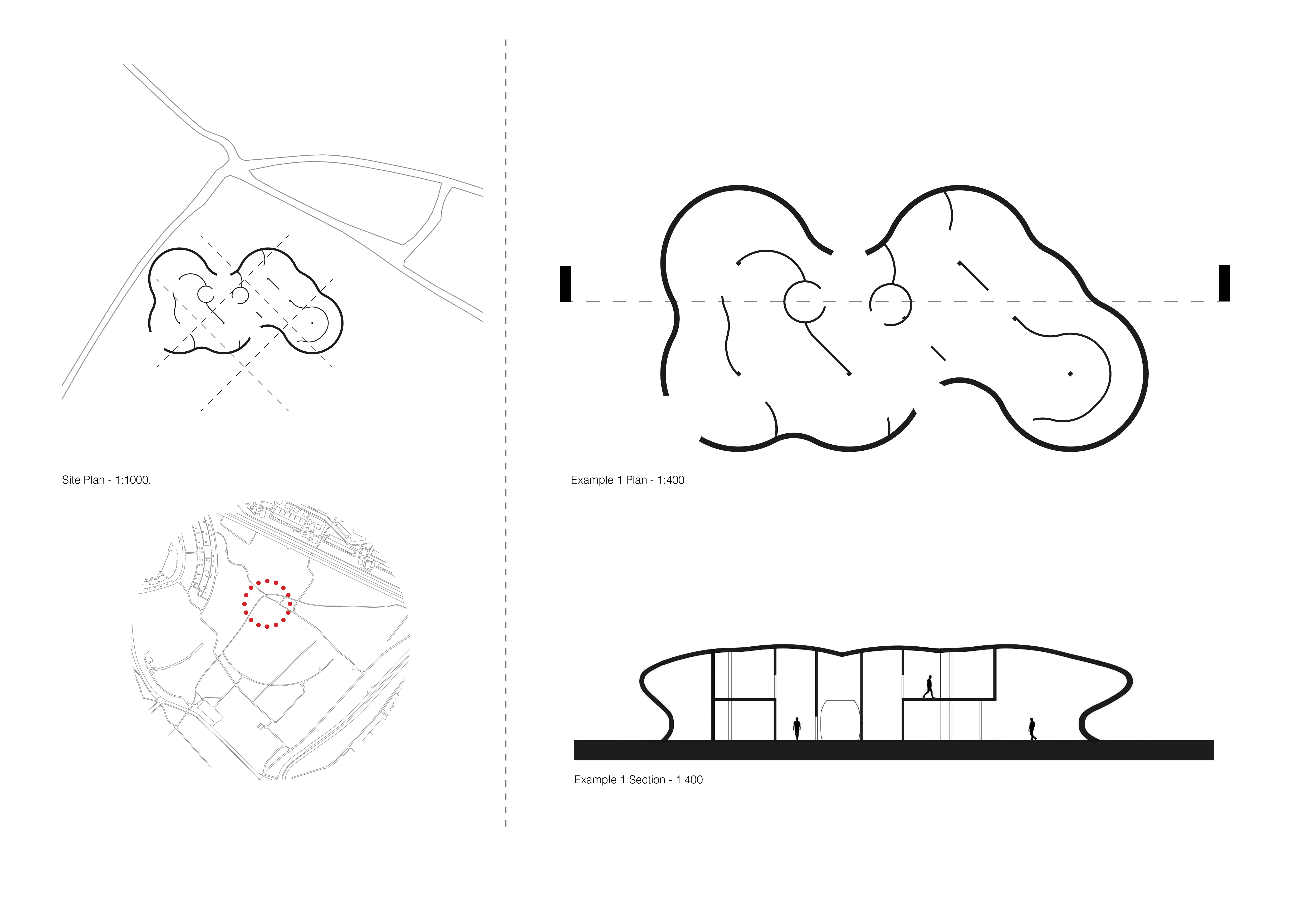
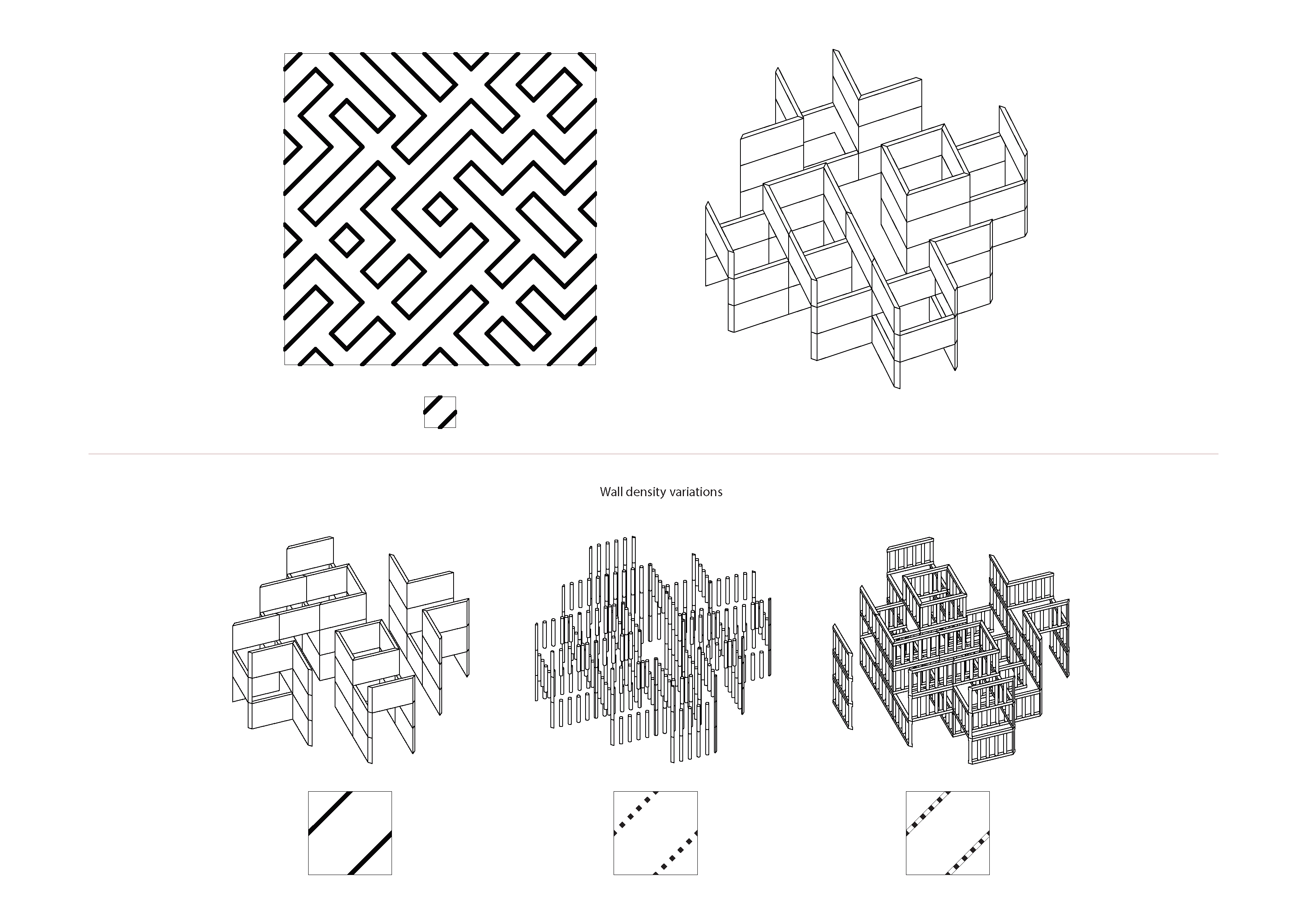
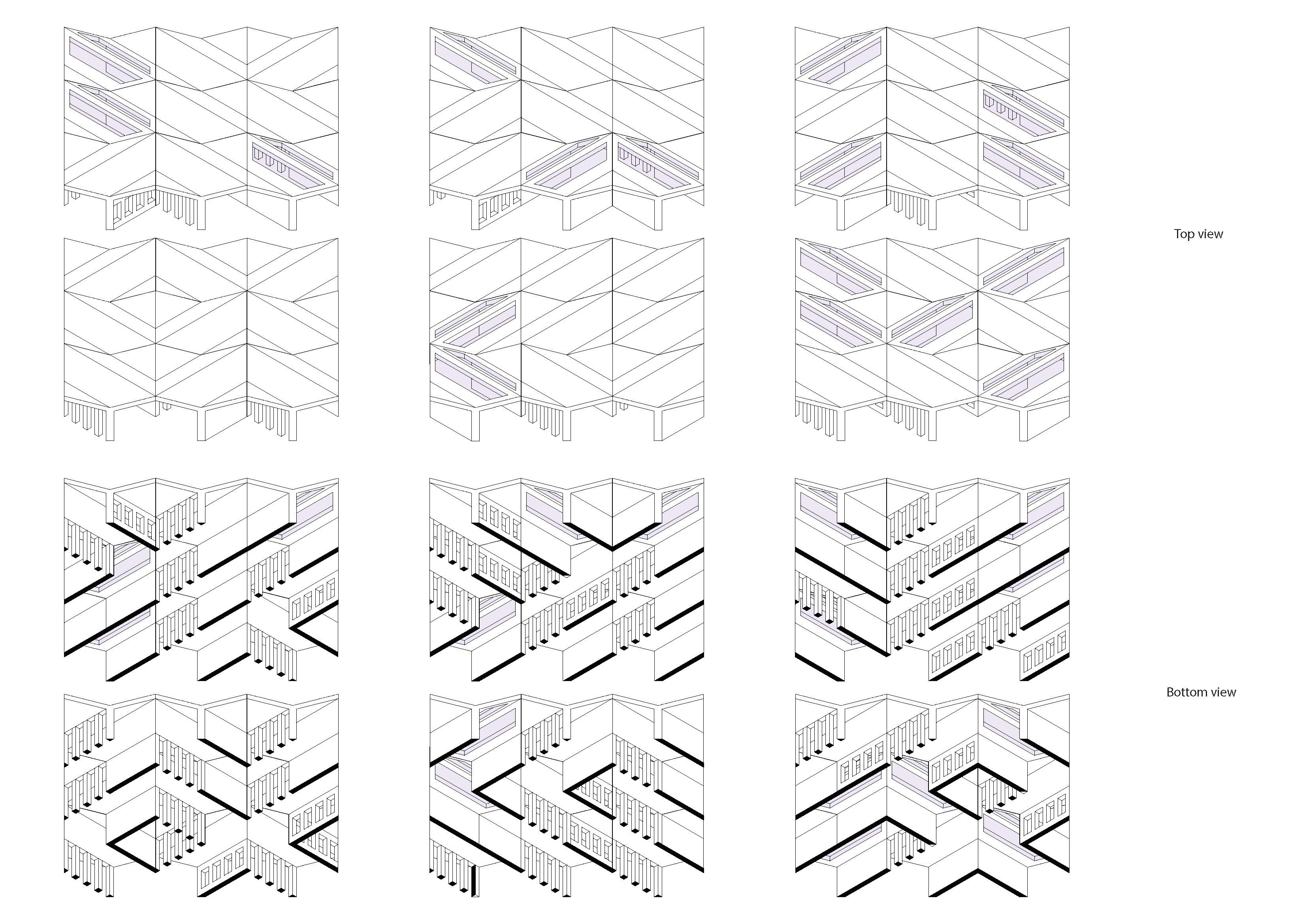
The challenge of using the curved walls as a guide without the roof structure deterring from the spatial experience was a balance difficult to navigate. The design needs to be explored at multiple locations within the curvature, based on site variations and the specific spatial qualities created at each chosen point. How the spaces are occupied, what potential it holds for exhibition purposes etc.

Plan

Curvature from Rotation

The final design in this project comes from a combination of results from the original Python code. The standard grid of points was moved and rotated around the mid-point of the grid along the x and y axis. This created two different sets of spatial organisations between the dots. Meshing between these points revealed two interesting shapes.

8.png

9.png


The more captivating outcome, however, was when circles were used to join the points that would have been equidistant in the original, two-dimensional grid.

11.png

12.png

The interesting spatial configuration was not only  the shapes themselves, but the residual space between them. The undulating surface works as a natural floor plan with gradual curvature, while the shape with more accentuated curves serves as a roof structure.

13.png

15.gif

17.png

18.png

28 grids later.

Previously I began to develop how my grid system would work in a 3-dimensional form. Offsetting the building boundary as it is extruded vertically, I experimented with different curve patterns to see how the external form could be generated.

A

Combining this with my 2-dimensional coding system, I generated an example layout. This created an initial layout in plan and section, along with an axonometric view of the roof, allowing me to begin to see how the interior spaces could develop.

B

B2

B3

To explore how this form could work tectonically, I built a structural model of the exterior boundary. Using this I hope to explore further how this layer can interact with the internal spaces for the gallery.

DSC_0638DSC_0644DSC_0655DSC_0662

Light and Leading Lines

Looking into the Venn Diagram roof structure, it has several parameters that can be varied. The angle is defined by the direction of the path, however the spacing, thickness and depth of the beams can be varied to achieve a certain level of light, or a certain atmosphere in the space below. By using Grasshopper the parameters can be quickly tested.  

Screen Shot 2018-10-29 at 21.57.47

This set of 3D printed models of the roof system keeps one circle constant while changing one parameter in the other circle. This shows the difference in the shadow effect, and how the appearance of the overlapping area changes. (Scale – 1:200)

Screen Shot 2018-10-29 at 21.57.56

In this model, at a larger scale (1:100), I am investigating a more complex Venn diagram with three intersecting circles. By varying all three parameters in each circle, the different levels of lighting can be observed in the shadows. 

Screen Shot 2018-10-29 at 21.58.14

The paths that generate the spaces provide more opportunity to express themselves. As they travel across the boundary, they can take the form of indoor and outdoor paths, windows, roof structure and ground level features such as steps or seating:

Screen Shot 2018-10-29 at 21.58.26Screen Shot 2018-10-29 at 21.58.42